


Type 201 / Type 211 - Cable de arrastre armado BS 6708, 640/1100 V
Cable minero Type 201 / Type 211 para extensiones de galería de mina, arrastre en cantera mecánicamente protegido e iluminación del frente de carbón, con la clasificación de 640/1100 V y la referencia de ensayo de 2,5 kV definidas en la fuente.
- Modelo: Type 201 / Type 211
- Conductor y aislamiento: cobre estañado flexible con el aislamiento y la construcción de núcleo indicados para este modelo en el PDF suministrado
- Disposición de pantalla, piloto, tierra y armadura conservada de la hoja de datos de origen
- Protección exterior de cloropreno o PCP de alta resistencia, según lo indicado para este modelo
- Hoja de datos original del Type disponible como descarga del producto
Envíe el equipo, la tensión, el área del conductor, la ruta, la cantidad y los requisitos de documentación para una solicitud de cotización.
Type 201 / Type 211 para extensiones de galería de mina, arrastre en cantera mecánicamente protegido e iluminación del frente de carbón
El cable minero Type 201 / Type 211 se especifica en la hoja de datos BS 6708 suministrada para extensiones de galería de mina, arrastre en cantera mecánicamente protegido e iluminación del frente de carbón.
La construcción suministrada utiliza tres conductores de potencia flexibles de cobre recocido estañado con aislamiento MEPR y pantallas de fase de cobre/nailon, armadura flexible de hilo de acero galvanizado y una chaqueta negra de PCP con banda amarilla. Esa disposición es importante porque el Type 201 tiene tres conductores de potencia apantallados; el Type 211 añade un conductor de tierra sin apantallar. Ambos utilizan armadura y la chaqueta general con banda amarilla descrita en el PDF. Por lo tanto, la familia debe seleccionarse por modelo, función de los conductores y ruta de instalación, además de por la tensión. Gama de cables para minería y túneles ofrece el contexto más amplio de productos de TEBAOFLEX.
- Elegir por: confirme si el Type 201 sin conductor de tierra o el Type 211 con un conductor de tierra sin apantallar coincide con el equipo y el circuito de protección.
- Confirmar antes de realizar el pedido: el marcado existente de la cubierta, el área del conductor, la longitud del cable, la ruta, el sistema de soporte o manejo, las terminaciones y los documentos de inspección requeridos.
- No infiera: valores no indicados en el PDF suministrado, como una base de corriente diferente, el comportamiento frente a agua/aceite/UV, el alcance de certificación o la intercambiabilidad mecánica.
Cuando se sustituye un cable de arrastre armado, la Guía de sustitución de cables mineros BS 6708 ayuda a mantener las verificaciones de tensión, armadura y familia de modelo en la misma revisión.
Para una cotización técnica, envíe la placa de identificación del equipo o el marcado del cable existente, el requisito de tensión y tamaño, las condiciones de instalación, la cantidad, el destino y cualquier requisito de ensayo o documentación específico del proyecto.
Construcción del Type 201 / Type 211
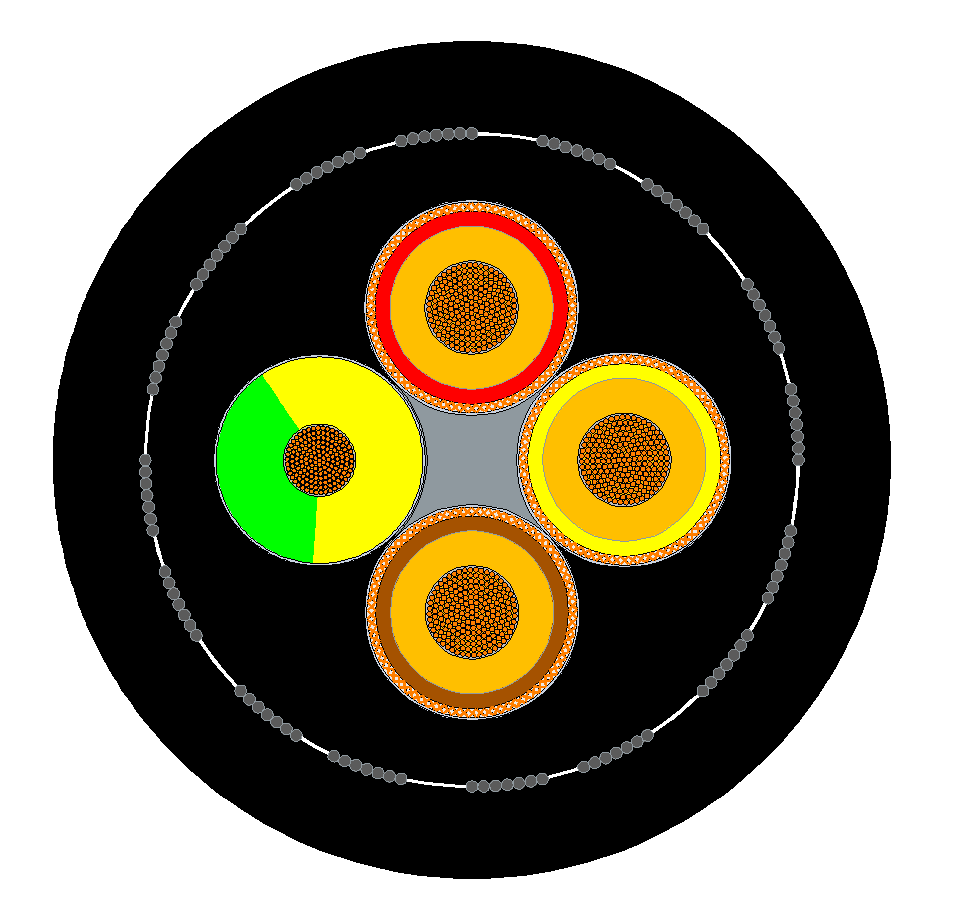
La sección transversal a continuación es el dibujo de construcción suministrado para el Type 201 / Type 211. La decisión de pedido se basa en que el Type 201 tiene tres conductores de potencia apantallados; el Type 211 añade un conductor de tierra sin apantallar. Ambos utilizan armadura y la chaqueta general con banda amarilla descrita en el PDF.
Construcción indicada por la fuente
| Elemento de construcción | Valor indicado por la fuente |
|---|---|
| Conductores aislados de potencia | Tres conductores flexibles de cobre recocido estañado, con aislamiento MEPR y pantalla de cobre/nailon |
| Type 201 | Tres conductores de potencia cableados alrededor de un centro de cuna elastomérica |
| Type 211 | Tres conductores de potencia más un conductor de tierra sin apantallar alrededor de un centro elastomérico |
| Capa de asiento | Cubierta de asiento de PCP extruida |
| Armadura | Armadura flexible de hilo de acero galvanizado |
| Chaqueta general | Compuesto elastomérico ignífugo de alta resistencia, PCP negro con banda amarilla |
No utilice el dibujo como sustituto de las tablas dimensionales. Confirme la preparación del extremo del cable, la terminación de pantalla y tierra, la conexión de la armadura y la interfaz de la máquina con la documentación del equipo antes de la instalación.
Aplicaciones del Type 201 / Type 211
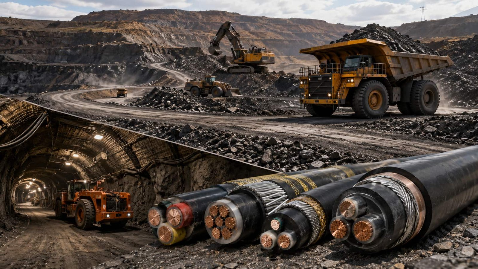
La hoja de datos suministrada identifica este cable para extensiones de galería de mina, arrastre en cantera mecánicamente protegido e iluminación del frente de carbón.
- Servicio principal: extensiones de galería de mina, arrastre en cantera mecánicamente protegido e iluminación del frente de carbón.
- Límite del modelo: El Type 201 tiene tres conductores de potencia apantallados; el Type 211 añade un conductor de tierra sin apantallar. Ambos utilizan armadura y la chaqueta general con banda amarilla descrita en el PDF.
- Verificación del proyecto: haga coincidir el marcado del cable, el mapa de conductores, la tensión, la terminación, la geometría de la ruta y el método de manejo con el plano de la máquina.
- Revisión ambiental: confirme las condiciones reales de la mina/cantera y cualquier requisito de autoridad, inspección o documentación; no infiera una declaración de certificación o resistencia de material a partir del número de modelo.
Para una ruta de arrastre armada de 1900/3300 V, consulte el cable minero Type 321/331 familia como comparación de mayor tensión, sujeta al diseño del equipo.
El cable debe liberarse solo después de acordar la ruta del equipo, la longitud requerida, el área del conductor, las funciones de los conductores y los detalles de conexión. Si el servicio previsto difiere de la aplicación indicada en la fuente, solicite una revisión de ingeniería a través del proceso de cotización.
Especificaciones del Type 201 / Type 211
El resumen a continuación identifica la familia de modelos suministrada. Las tablas transcritas de la fuente que siguen conservan los valores dimensionales, eléctricos y constructivos del PDF, incluidos los tamaños disponibles, la resistencia, la corriente, el diámetro, la masa y los datos de curvatura o tracción cuando el PDF los proporciona.
| Elemento de selección | Valor vinculado a la fuente |
|---|---|
| Modelo | Type 201 / Type 211 |
| Tensión asignada | 640/1100 V |
| Tensión de ensayo | 2,5 kV |
| Aplicación | extensiones de galería de mina, arrastre en cantera mecánicamente protegido e iluminación del frente de carbón |
| Norma del producto | BS 6708:1998 |
Tablas técnicas completas transcritas de la fuente
PDF de origen: BS6708_TYPE_201_TYPE_211_640_1100V_ARMOURED_TRAILING_CABLE_datasheet.pdf; 4 páginas; 6 tablas extraídas. Los valores no se recalculan ni se sustituyen por valores de terceros.
| Parámetro | Valor |
|---|---|
| Conductor | Tres conductores flexibles de cobre recocido estañado, con aislamiento MEPR y pantalla de cobre/nailon |
| Type 201 | Tres conductores de potencia cableados alrededor de un centro de cuna elastomérica |
| Type 211 | Tres conductores de potencia más un conductor de tierra sin apantallar, cableados alrededor de un centro elastomérico |
| Capa de asiento | Cubierta de asiento de PCP extruida |
| Armadura | Armadura flexible de hilo de acero galvanizado |
| Chaqueta general | Compuesto elastomérico ignífugo de alta resistencia, PCP negro con banda amarilla |
| Parámetro | Valor |
|---|---|
| Norma | BS 6708:1998 |
| Tensión asignada | 640/1100 V |
| Tensión de ensayo | 2,5 kV |
| Identificación de fase | Rojo, amarillo y marrón |
| Conductor de tierra del Type 211 | Conductor de tierra sin apantallar con identificación verde/amarillo |
| DIMENSIONES DEL CABLE TYPE 201 | ||||||||
|---|---|---|---|---|---|---|---|---|
| Parámetro | 10 | 16 | 25 | 35 | 50 | 70 | 95 | 120 |
| Diámetro nominal sobre aislamiento y cinta mm | 7.70 | 9.15 | 10.65 | 11.90 | 13.90 | 16.00 | 17.55 | 20.35 |
| Diámetro nominal sobre pantalla mm | 9.70 | 11.15 | 12.65 | 13.90 | 15.90 | 18.00 | 19.55 | 22.35 |
| Diámetro sobre cubierta interior - mínimo mm | 25.50 | 28.70 | 32.20 | 35.20 | 39.50 | 44.50 | 52.50 | 56.60 |
| Diámetro sobre cubierta interior - máximo mm | 27.50 | 30.70 | 34.20 | 37.20 | 41.50 | 47.00 | 55.50 | 59.60 |
| Diámetro total - mínimo mm | 37.30 | 40.60 | 44.60 | 48.30 | 53.60 | 60.70 | 71.80 | 76.70 |
| Diámetro total - máximo mm | 39.80 | 43.40 | 47.40 | 51.10 | 57.40 | 64.50 | 75.80 | 81.00 |
| Radio mínimo de curvatura (mm) | 400 | 440 | 480 | 510 | 580 | 650 | 760 | 810 |
| Tracción máxima de tiro kgf | 180 | 290 | 450 | 630 | 900 | 1260 | 1710 | 2000 |
| Peso aproximado del cable (kg/km) | 2900 | 3400 | 4100 | 4800 | 5900 | 7700 | 10900 | 12500 |
| DIMENSIONES DEL CABLE TYPE 211 | ||||||||
|---|---|---|---|---|---|---|---|---|
| Parámetro | 10 | 16 | 25 | 35 | 50 | 70 | 95 | 120 |
| Diámetro de fase sobre aislamiento y cinta mm | 7.70 | 9.15 | 10.65 | 11.90 | 13.90 | 16.00 | 17.55 | 20.35 |
| Diámetro de fase sobre pantalla mm | 9.70 | 11.15 | 12.65 | 13.90 | 15.90 | 18.00 | 19.55 | 22.35 |
| Sección nominal del conductor de tierra mm² | 10 | 16 | 16 | 25 | 35 | 50 | 70 | 70 |
| Diámetro de tierra sobre aislamiento y cinta mm | 9.70 | 11.15 | 12.65 | 13.90 | 15.90 | 18.00 | 19.55 | 22.35 |
| Diámetro sobre cubierta interior - mínimo mm | 27.90 | 31.60 | 35.40 | 38.80 | 43.70 | 51.80 | 60.30 | 64.90 |
| Diámetro sobre cubierta interior - máximo mm | 29.90 | 33.60 | 37.40 | 40.80 | 46.20 | 54.80 | 63.30 | 67.90 |
| Diámetro total - mínimo mm | 39.80 | 44.00 | 48.50 | 52.70 | 59.70 | 68.80 | 80.60 | 86.20 |
| Diámetro total - máximo mm | 42.30 | 46.80 | 51.30 | 56.50 | 63.50 | 72.80 | 84.90 | 90.50 |
| Radio mínimo de curvatura (mm) | 430 | 470 | 520 | 570 | 640 | 730 | 850 | 910 |
| Tracción máxima de tiro kgf | 240 | 380 | 540 | 780 | 1110 | 1560 | 2000 | 2000 |
| Peso aproximado del cable (kg/km) | 3200 | 3900 | 4700 | 5600 | 7300 | 9500 | 13300 | 15400 |
| DETALLES ELÉCTRICOS DEL TYPE 201 | ||||||||
|---|---|---|---|---|---|---|---|---|
| Parámetro | 10 | 16 | 25 | 35 | 50 | 70 | 95 | 120 |
| Capacidad de corriente continua a 25 °C ambiente A | 63 | 85 | 110 | 135 | 170 | 205 | 250 | 295 |
| Resistencia CC del conductor de potencia a 20 °C Ω/km | 1.950 | 1.240 | 0.795 | 0.565 | 0.393 | 0.277 | 0.210 | 0.164 |
| Resistencia CC de pantallas en paralelo Ω/km | 1.330 | 1.610 | 1.100 | 1.200 | 1.400 | 0.700 | 0.850 | 0.500 |
| Resistencia CC de la armadura a 20 °C Ω/km | 1.970 | 1.760 | 1.450 | 1.030 | 0.715 | 0.504 | 0.382 | 0.299 |
| Reactancia nominal a 50 Hz Ω/km | 0.121 | 0.111 | 0.107 | 0.102 | 0.099 | 0.097 | 0.096 | 0.095 |
| Reactancia nominal a 60 Hz Ω/km | 0.145 | 0.134 | 0.128 | 0.123 | 0.119 | 0.116 | 0.116 | 0.114 |
| Resistencia mín. de aislamiento de conductores de potencia MΩ/km | 560 | 435 | 375 | 325 | 285 | 260 | 250 | 250 |
| Caída de tensión trifásica a 50 Hz mV/A/m | 4.11 | 2.62 | 1.68 | 1.20 | 0.85 | 0.61 | 0.47 | 0.38 |
| DETALLES ELÉCTRICOS DEL TYPE 211 | ||||||||
|---|---|---|---|---|---|---|---|---|
| Parámetro | 10 | 16 | 25 | 35 | 50 | 70 | 95 | 120 |
| Capacidad de corriente continua a 25 °C ambiente A | 63 | 85 | 110 | 135 | 170 | 205 | 250 | 295 |
| Resistencia CC del conductor de potencia a 20 °C Ω/km | 1.950 | 1.240 | 0.795 | 0.565 | 0.393 | 0.277 | 0.210 | 0.164 |
| Resistencia CC del conductor de tierra a 20 °C Ω/km | 1.950 | 1.240 | 1.240 | 0.795 | 0.565 | 0.393 | 0.277 | 0.277 |
| Resistencia CC de pantallas en paralelo Ω/km | 1.330 | 1.610 | 1.100 | 1.200 | 1.400 | 0.700 | 0.850 | 0.500 |
| Resistencia CC de la armadura a 20 °C Ω/km | 1.810 | 1.630 | 1.450 | 1.030 | 0.715 | 0.504 | 0.382 | 0.299 |
| Reactancia nominal a 50 Hz Ω/km | 0.121 | 0.111 | 0.107 | 0.102 | 0.099 | 0.097 | 0.096 | 0.095 |
| Reactancia nominal a 60 Hz Ω/km | 0.145 | 0.134 | 0.128 | 0.123 | 0.119 | 0.116 | 0.116 | 0.114 |
| Resistencia mín. de aislamiento de conductores de potencia MΩ/km | 560 | 435 | 375 | 325 | 285 | 260 | 250 | 250 |
| Caída de tensión trifásica a 50 Hz mV/A/m | 4.11 | 2.62 | 1.68 | 1.20 | 0.85 | 0.61 | 0.47 | 0.38 |
Utilice los valores de la tabla junto con el plano del equipo y el plan de terminación aprobado. Si el área de conductor solicitada, la base de corriente, el límite mecánico o la condición ambiental no está indicada en el PDF suministrado, trátela como un elemento de confirmación en la etapa de cotización.
Normas y referencias del Type 201 / Type 211
| Asunto | Referencia vinculada a la fuente |
|---|---|
| Norma del producto | BS 6708:1998 |
| Tensión asignada | 640/1100 V |
| Tensión de ensayo | 2,5 kV |
| Aplicación indicada por la fuente | extensiones de galería de mina, arrastre en cantera mecánicamente protegido e iluminación del frente de carbón |
La página del producto conserva la referencia BS 6708 que aparece en el PDF suministrado. El registro de la BSI identifica actualmente la BS 6708:1998 como retirada el 22 de mayo de 2026; esta nota de estado es una actualización de referencia normativa, no una declaración de que el producto está actualmente certificado o aprobado. Consulte el registro oficial de alcance de la BSI para BS 6708 para conocer el estado publicado.
Para una solicitud de cotización, indique los documentos normativos requeridos, el alcance de la inspección, el informe de ensayo, el marcado del cable, las normas de destino y cualquier requisito de equivalencia de sustitución. El número de modelo por sí solo no establece el cumplimiento legal de la instalación.
Opciones de cable relacionadas
Compare estas opciones de cable según la combinación de funciones, el movimiento, la carga, la tensión y los requisitos de transmisión.
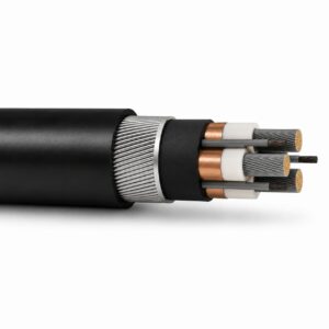
Cable de alimentación para minería tipo 260, armado y apantallado
Una opción de cable relacionada para una aplicación o perfil de trabajo diferente.
Ver producto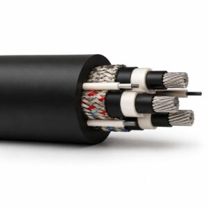
Cable subterráneo para minas de carbón tipo 240 de 1.1 kV a 11 kV
Una opción de cable relacionada para una aplicación o perfil de trabajo diferente.
Ver producto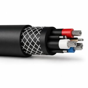
Cable minero tipo 241.1 de 1.1 kV | Familia tipo 241
Una opción de cable relacionada para una aplicación o perfil de trabajo diferente.
Ver productoSolicite una recomendación y una cotización de cables.
Indique las funciones requeridas, la longitud del cable, las exigencias mecánicas, el entorno, el tipo de terminación y la cantidad. Nuestro equipo revisará la aplicación antes de preparar la cotización.
- Incluya el nombre del producto o SKU, así como la longitud y la cantidad de cable requeridas.
- Adjunte una especificación, un dibujo o una hoja de datos cuando esté disponible.