








Medium-Voltage Distribution & Mining Feeders · 5 kV, 15 kV, 25 kV & 35 kV
Type MV-105 cable is a shielded medium-voltage power cable engineered to UL 1072 and ICEA S-93-639 reference constructions for 5 kV through 35 kV fixed industrial, substation, renewable and mine-infrastructure distribution at a continuous conductor temperature of +105 °C (+140 °C emergency overload, +250 °C short-circuit). Getting a Type MV-105 specification right hinges on four decisions: selecting the 100% vs 133% insulation level for your ground-fault clearing time, choosing EPR vs TR-XLPE insulation, sizing metallic copper-tape or concentric-wire shields for circulating current, and confirming whether a mining route actually requires Type MP-GC or portable Type SHD-GC instead.
How does Type MV-105 differ from Type MV-90 and IEC 60502-2 medium-voltage feeders?
Across North American, Latin American (such as Peru, Chile and Mexico) and Middle East industrial projects, tenders routinely mix North American Type MV-105 (UL 1072 / ICEA S-93-639) alongside European or international IEC 60502-2 feeders (such as NA2XSEY or N2XS2Y). Recognizing the exact thermal and voltage-designation split avoids incompatible terminations and ampacity errors:
- MV-105 vs MV-90 thermal ceiling: Type MV-90 is rated +90 °C continuous / +130 °C emergency, whereas Type MV-105 elevates continuous conductor operation to +105 °C (+140 °C emergency, +250 °C short-circuit). Under NEC Article 310 tables, +105 °C EPR Type MV-105 typically yields 7 % to 11 % higher ampacity in identical conduit or tray conditions—or provides extra insulation-aging life when terminations limit actual load temperature to 90 °C.
- Phase-to-phase vs U₀/U rating convention: UL 1072 / ICEA S-93-639 names Type MV-105 by phase-to-phase system voltage class (5 kV, 15 kV, 25 kV, 35 kV) paired with an explicit 100% or 133% insulation level. IEC 60502-2 names U₀/U (Um), such as 12/20(24) kV or 18/30(36) kV. Never substitute a 12/20 kV IEC feeder onto a 35 kV MV-105 tender, and verify stress-cone outer diameter compatibility when mixing AWG/kcmil and metric mm² lugs.
What are the 100% vs 133% insulation wall thicknesses from 5 kV to 35 kV?
Choosing between the 100% insulation level und 133% insulation level is a system-grounding decision, not a quality grade. During a single-line-to-ground fault on a resistance-grounded or ungrounded industrial bus, healthy phases experience line-to-line voltage (1.732 × normal phase-to-ground voltage) until relays isolate the faulted feeder. Thicker 133% dielectric walls absorb that elevated electrical stress safely for up to 1 hour without premature partial-discharge inception.
| Nennspannungsklasse | 100% level wall (≤ 1 min fault clear) | 133% level wall (≤ 1 hr / ungrounded) | Minimum conductor size (ICEA/UL ref.) | Typical industrial & substation role |
|---|---|---|---|---|
| 5 kV (shielded) | 90 mil (2.29 mm) | 115 mil (2.92 mm) | 8 AWG (shielded) | 4.16 kV plant motors, crushers, pump feeders |
| 8 kV (shielded) | 115 mil (2.92 mm) | 140 mil (3.56 mm) | 6 AWG | 6.6–7.2 kV industrial & mine substations |
| 15 kV (shielded) | 175 mil (4.45 mm) | 220 mil (5.59 mm) | 2 AWG | 13.8 kV primary plant loops, wind/solar collectors |
| 25 kV (shielded) | 260 mil (6.60 mm) | 320 mil (8.13 mm) | 1 AWG | 22–25 kV mine perimeter & utility feeders |
| 35 kV (shielded) | 345 mil (8.76 mm) | 420 mil (10.67 mm) | 1/0 AWG | 33–35 kV unipolar substation tie & Andean mine feeds |
Should your 15 kV or 35 kV Type MV-105 feeder use EPR or TR-XLPE insulation?
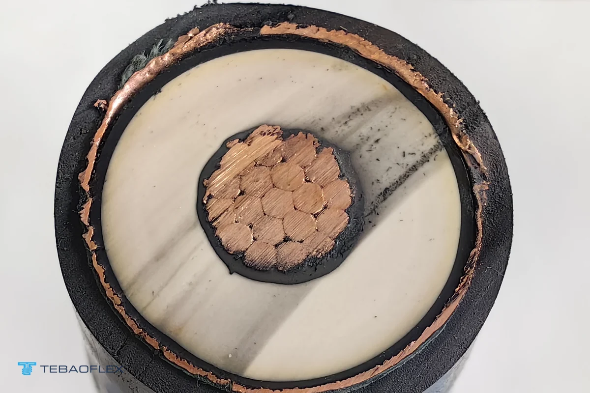
Although UL 1072 permits both ethylene propylene rubber (EPR / HEPR) and cross-linked polyethylene (TR-XLPE) at 105 °C on select qualified compounds, industrial, refinery and mining engineers overwhelmingly favor EPR für 15 kV to 35 kV Type MV-105 EPR distribution cables und 5 kV to 15 kV flexible EPR MV-105 feeders. For deep polymer physics, compare our dedicated Leitfaden zur EPR-Isolierung und XLPE / TR-XLPE insulation guide:
- Tight switchgear & wet-duct bending: EPR retains rubbery flexibility even at 345 to 420 mil (8.8 to 10.7 mm) wall thickness, lowering pulling sidewall pressure around conduit elbows and simplifying termination inside cramped 15 kV or 35 kV metal-clad switchgear cabinets.
- Water-treeing & partial-discharge resistance: Mineral-filled EPR resists moisture-driven water treeing and localized electrical tree propagation in flooded underground ducts and mine drainage trenches, whereas standard XLPE relies on tree-retardant additives (TR-XLPE) and strict moisture exclusion.
- Emergency thermal stability (+140 °C): XLPE is semicrystalline and softens sharply near its ~105–110 °C crystalline melting range under heavy overload, increasing thermo-mechanical deformation at sharp cable-tray rungs; amorphous cross-linked EPR maintains modulus smoothly up to +140 °C emergency duty.
How do copper tape shields (CTS) vs concentric wire shields affect 15 kV and 35 kV bonding?
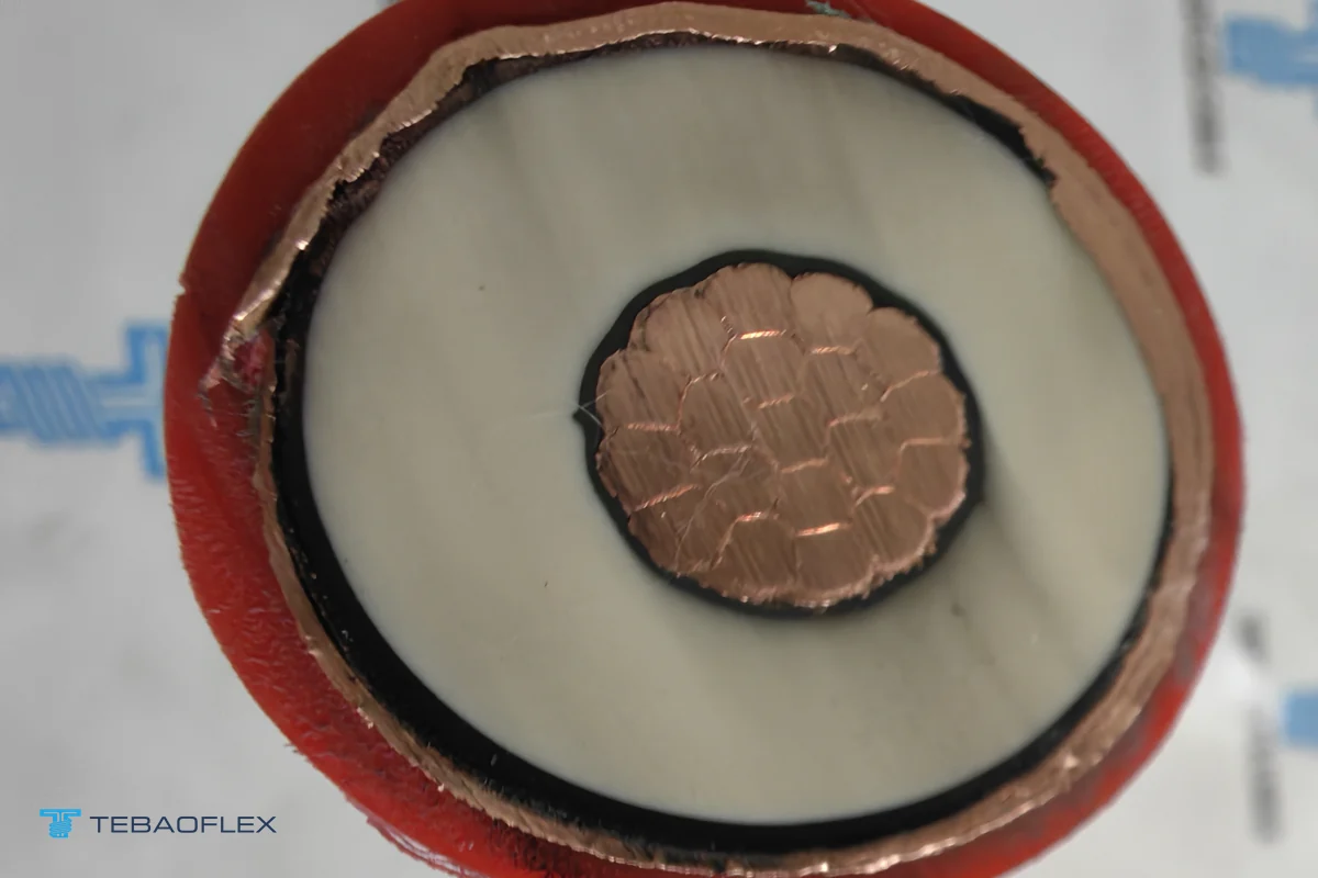
Every shielded Type MV-105 cable encloses its outer semiconductive layer in a metallic shield that confines the radial electric field and drains capacitive charging current and ground-fault current safely to earth. Two metallic shield styles dominate industrial MV-105 schedules:
- Helically applied 5 mil bare copper tape shield (CTS, ≥ 12.5 % to 25 % overlap): The most compact, economical shield for fixed trays, ducts and substations where short-circuit ground-fault current is moderate or supplemented by an external equipment grounding conductor.
- Concentric copper wire shield (drain wires / LC longitudinal corrugated tape): Provides much higher symmetrical fault-current cross-section and superior mechanical tolerance against longitudinal thermal expansion—preferred on high-fault utility tie lines and direct-buried 25 kV / 35 kV circuits.
Critical 35 kV single-core bonding rule: On three single-core 15 kV or 35 kV Type MV-105 cables routed in flat or trefoil formation, bonding metallic shields solidly at both ends induces continuous circulating shield current driven by phase load current—which can cut continuous ampacity by 5 % to 20 % on large conductors (250 kcmil to 1,000 kcmil). For short substation runs (< 100 m) or moderate current, engineers often apply single-point shield bonding with a surge-limiting arrestor (SVL) at the unbonded end, or verify exact trefoil derating before sizing conductors.
When should mines and plants step from Type MV-105 to Type MP-GC or portable Type SHD-GC?
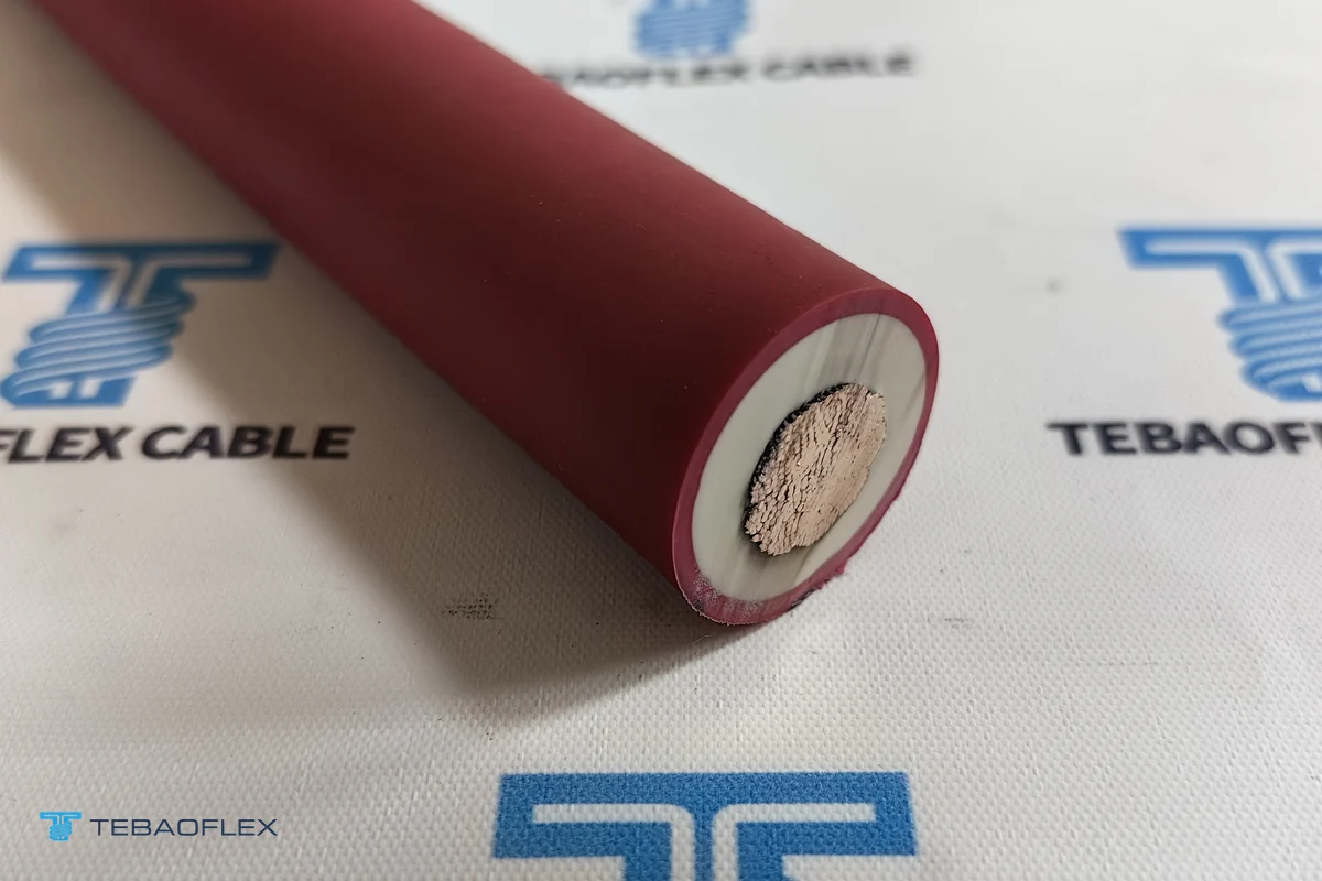
Selecting the wrong mechanical duty class is the most expensive mistake in medium-voltage mining procurement. While a fixed Type MV-105 feeder carries the highest thermal ceiling (+105 °C), it is built with Class B (7–61 wire) stranded conductors and lacks the extra-flexible rope-lay copper, heavy ground-check pilot core and double-reinforced CPE jacket required for mobile drag or shovel trailing. Compare the three families across our Auswahlleitfaden für Mittelspannungs-Bergbaukabel, armored and static mining cable guide und SHD-GC 2 kV to 25 kV voltage ratings guide:
| Technischer Parameter | Type MV-105 (Fixed Distribution) | Type MP-GC (Semi-Permanent Mine Feeder) | Type SHD-GC / 35-CHVU (Mobile Trailing) |
|---|---|---|---|
| Governing reference | UL 1072 / ICEA S-93-639 | ICEA S-75-381 (mine power feeder) | ICEA S-75-381 (portable trailing) |
| Voltage & thermal class | 5–35 kV · +105 °C continuous | 5–25 kV · +90 °C continuous | 2–25 kV (SHD-GC) / 20/35 kV (35-CHVU) · +90 °C |
| Conductor flexibility | Class B / Class 2 (or flexible MV-105 Class G/H) | Class B or flexible Class C/G stranded | Extra-flexible Class 5 / Class 6 / rope-lay |
| Ground-check (GC) monitor core | Not included (unless hybrid MV-105/MP-GC) | Integrated 2 grounding + 1 insulated GC core | Integrated 2 grounding + 1 yellow GC pilot core |
| Mechanical installation mode | Fixed cable tray, conduit, duct bank, direct burial | Mine shafts, haulage drifts, relocatable substation feeds | Continuous dragging behind shovels, drills & draglines |
| TEBAOFLEX product & proof | Type MV-105 15–35 kV · Armored MV-105/MP-GC | Type MP-GC EPR/CPE Mine Feeder | SHD-GC · 35-CHVU 20/35 kV · Peru 8 kV Case |
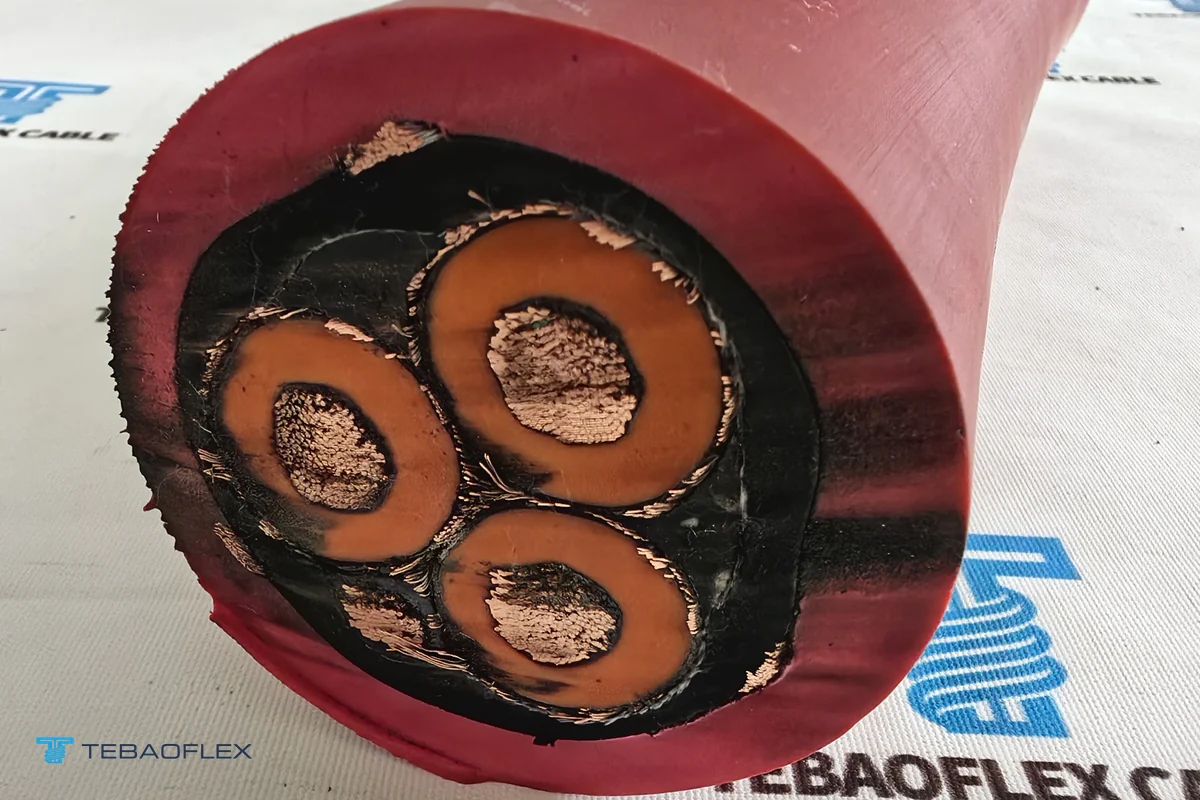
What factory tests and 6 RFQ items prevent costly Type MV-105 specification delays?
Medium-voltage EPR cables from 5 kV to 35 kV must pass strict routine electrical screening before leaving the factory floor—specifically conductor DC resistance, high-voltage AC withstand testing and partial-discharge (PD) extinction testing verifying void-free triple extrusion across the inner screen, EPR dielectric and outer insulation screen (see our cable factory acceptance test guide for routine vs sample vs type test definitions).
When requesting a quotation for single-core or three-core Type MV-105 cable (including short custom replacement lengths such as 300 m per phase), confirm six items upfront:
- Exact system voltage & insulation level: State 5 kV, 8 kV, 15 kV, 25 kV or 35 kV and confirm 100% vs 133% insulation wall based on your relay ground-fault clearing time.
- Single-core vs three-core & conductor metal: Specify unipolar (1/C) or triplexed/jacketed 3/C, copper vs aluminum conductor, and AWG/kcmil or mm² cross-section (confirming compatibility with your existing termination kits).
- Dielectric & shield style: Confirm EPR vs TR-XLPE insulation and 5 mil copper tape shield (CTS) vs concentric copper wire shield (plus required short-circuit fault-current duration).
- Outer sheath & optional armor: Specify sunlight-resistant PVC, heavy-duty oil-resistant CPE, halogen-free LSZH, or interlocked/polymeric armor for tray or direct-burial exposure.
- Reel length, net/gross drum mass & freight mode: Confirm continuous cut length per wooden or steel export drum and port Incoterms (e.g., FOB Shanghai vs CIF Callao/Antofagasta/Jebel Ali—note that multi-ton MV drums carry substantial air-freight premiums if emergency schedules bypass ocean transit).
- Lead time & minimum order quantity: Custom Type MV-105 cables are manufactured to order from a 50 m MOQ with standard 7 to 45 working-day production windows. Send your Type MV-105 voltage class, insulation level and length schedule to TEBAOFLEX engineers for a tailored datasheet and factory quotation.
Häufig gestellte Fragen
What is the difference between Type MV-105 and Type MV-90 medium-voltage cables?
Both Type MV-90 and Type MV-105 follow UL 1072 and ICEA S-93-639 medium-voltage power-cable reference rules for 5 kV through 35 kV systems, but Type MV-105 is rated for +105 °C continuous wet/dry conductor temperature (+140 °C emergency overload, +250 °C short-circuit) versus +90 °C continuous (+130 °C emergency) for Type MV-90. That +15 °C thermal margin lets a Type MV-105 feeder carry higher ampacity in hot underground ducts or tropical ambient yards—or maintain safety margin when equipment terminations are rated at 90 °C.
How do you choose between the 100% and 133% insulation level on 5 kV, 15 kV or 35 kV Type MV-105 cable?
Under ICEA S-93-639 and UL 1072, the 100% insulation level applies to solidly grounded systems where protective relays clear a single-phase-to-ground fault within 1 minute (e.g., 175 mil at 15 kV, 345 mil at 35 kV). The thicker 133% insulation level (e.g., 220 mil at 15 kV, 420 mil at 35 kV) is required on resistance-grounded, ungrounded or industrial/mining networks where clearing a ground fault may take up to 1 hour, or where extra dielectric safety margin is specified against switching surges.
Should a 15 kV or 35 kV Type MV-105 feeder use EPR or TR-XLPE insulation?
Ethylene propylene rubber (EPR / HEPR) provides markedly higher flexibility, smaller bending radius, stronger corona and water-treeing resistance and superior thermal-cycling stability in wet trays, mine substations and tight switchgear cubicles—making EPR the dominant dielectric for industrial and mining Type MV-105 feeders. Tree-retardant XLPE (TR-XLPE) delivers slightly lower dielectric losses and smaller outer diameter on long, straight utility duct runs where pulling tension dominates over tight bends.
Why do 35 kV single-core Type MV-105 copper-tape shields require careful single-point vs both-end grounding analysis?
When three single-core 15 kV or 35 kV shielded cables run in parallel, AC magnetic flux induces circulating current in metallic copper-tape or concentric-wire shields if both ends are bonded directly to earth. On long, high-current feeders, circulating shield current adds I²R heat that derates conductor ampacity; engineers verify shield-bond topology (single-point bonding with sheath voltage limiters, cross-bonding, or both-end bonding with trefoil spacing) before commissioning.
When should an underground or open-pit mine specify Type MV-105 versus Type MP-GC or Type SHD-GC?
Specify Type MV-105 (single-core or three-core, unarmored or interlocked/polymeric armored) for fixed primary distribution in cable trays, underground conduits, substation tie feeders and direct-buried trenches. Step up to Type MP-GC when a semi-permanent mine feeder requires an integrated ground-check conductor for continuous ground-monitoring relays, and step up to flexible portable Type SHD-GC (or 35-CHVU) whenever the cable trails across rock behind mobile shovels, drills or substations.
Can TEBAOFLEX supply short custom lengths such as 300 m of 35 kV unipolar EPR Type MV-105 cable?
Yes. Utility distributors often enforce multi-kilometer factory minimums on 15 kV to 35 kV EPR medium-voltage cable, whereas TEBAOFLEX builds custom single-core and three-core Type MV-105 (5 kV, 15 kV, 25 kV and 35 kV) and polymeric-armored MV-105/MP-GC feeders starting from a 50 m MOQ, with standard manufacturing lead times of 7 to 45 working days and routine partial-discharge and AC withstand factory testing.