

Cable de encendido de alta tensión 25 kV, 250°C y 538°C
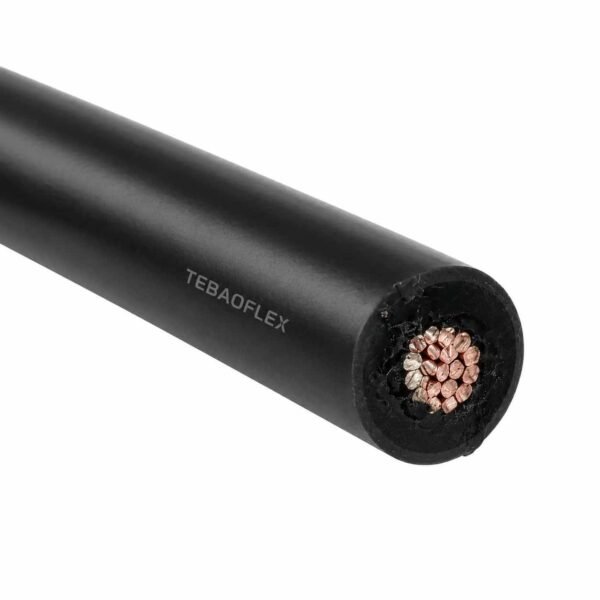
Cable de encendido de 25 kV en dos construcciones: mica/fibra de vidrio hasta 538 °C y fluoropolímero hasta 250 °C. Unipolar sin pantalla, fabricado a la longitud del recorrido.
- Valores nominales: 25 kV DC / 17 kV AC, ambos construye
- Construcción de 538 °C: multicapa cinta mica + barrera de humedad bajo fibra de vidrio trenzado
- Construcción de 250 °C: fluoropolímero extruido, Estilo UL AWM 1911
- Conductor: cobre finamente varado niquelado, estándar 18 AWG
- Típico OD: 8.6 mm (538 °C) / 2.49 mm (250 °C)
- Radio de curvatura: 6 × OD estática (538 °C) / 12 × OD estática (250 °C)
- Pantalla: ninguno - sin pantalla por diseño
Envíe la configuración, el tamaño y la longitud requeridos para recibir una cotización técnica.
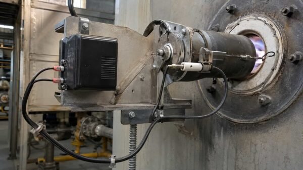
El alambre de ignífugo es el plomo entre el transformador de ignición o el excitador y la barra de chispa, y vive en el peor lugar en el vecindario de la cámara de combustión. TEBAOFLEX lo construye en 25 kV DC / 17 kV AC en dos construcciones que comparten la clase de voltaje y nada más:
A Construcción de mica y fibra de vidrio, clasificada a 538 °C (1,000 °F), donde el aislamiento es inorgánico porque ningún polímero sobrevive allí - cinta mica multicapa con una barrera de humedad bajo una trenza de fibra de vidrio impregnada. Y un fluoropolímero de construcción valorado 250 °C en Estilo UL AWM 1911, que comercializa la parte superior del rango de temperatura para un alambre inferior a un tercio del diámetro y una mayor resistencia al aceite, solvente y abrasión.
Ambos utilizan cobre finamente varado niquelado, ambos son núcleos únicos sin pantalla, y ambos están hechos a la longitud de ejecución entre su transformador y su varilla. El que usted necesita es decidido por un número: la temperatura que el conductor alcanza en realidad en el extremo terminal - no la temperatura ambiente, y no la temperatura de la llama.
Estos se sientan una clase completa sobre el motor 7–10 kV y el quemador conduce a otro lugar de nuestra gama, y por encima cable de encendido para antorcha, que es 25 kV DC pero sólo 10 kV AC y 250 °C. Para el cuadro completo de material y temperatura, vea el matriz de selección de conductores para alta temperatura y el resto del cable de alta temperatura gama.
Envíe la temperatura del conductor a la varilla, la salida del transformador y la longitud de ejecución, y le diremos cuál de los dos que debe comprar, incluso cuando la respuesta es la más barata.
Dos construcciones, una clase de tensión. El director y el trabajo son idénticos; el sistema de aislamiento es donde parte compañía, y esa elección establece el diámetro, la rigidez y el precio.
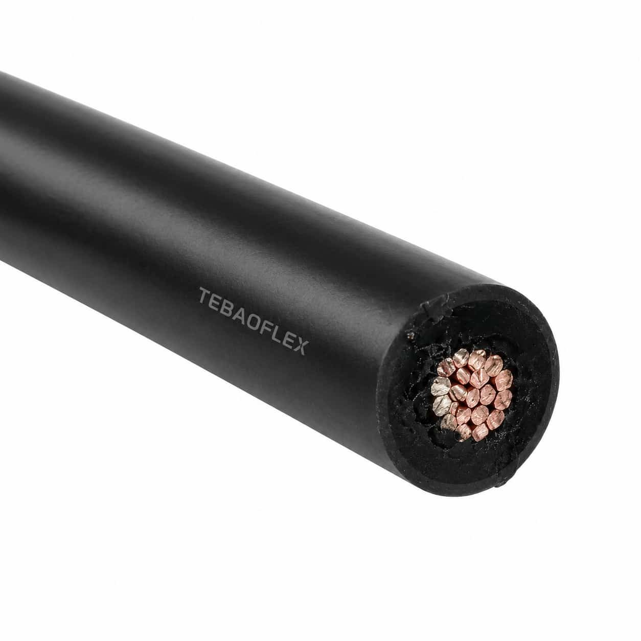
La construcción de 538 °C: mica y vidrio
- Conductor: finamente trenzado cobre niqueladoEstándar 18 AWG. Nickel no es una preferencia a esta temperatura, es el único platino común que sobrevive.
- Aislamiento: cinta multicapa, helicamente envuelto. Mica es un mineral, no un polímero, que es todo el punto. En 538 °C no queda plástico para derretir porque nunca había plástico haciendo el aislante.
- Barrera de humedad: un delgado Barrera PTFE en el envoltorio. La debilidad de Mica es que absorberá la humedad, y la mica húmeda no es un aislante. La barrera protege la envoltura durante el almacenamiento, instalación y lavado.
- Cubierta: una trenza de fibra de vidrio impregnada, terminado por lo que no fray cuando se corta y termina.
La construcción de 250 °C: fluoropolímero, UL AWM Style 1911
- Conductor: el mismo cobre de níquel finamente varado.
- Aislamiento: extrusión fluoropolímero, que es tanto la dieléctrica como la chaqueta. Una capa lo hace todo.
Es por eso que esta versión es una fracción del diámetro. También lleva un Número de estilo UL AWM, que la construcción de mica no puede, porque ningún estilo AWM describe una construcción de alto voltaje de mica y vidrio.
Por qué el caliente es más gordo y el fresco es más delgado
La cinta de Mica tiene que ser envuelta, no extruída, y una consoladora envuelta necesita muchos más giros para llegar a la misma soportar que un extrusionado necesita milímetros. Agregue el trenzado de cristal y la construcción 538 °C tierras en 8.6 mm sobre un conductor de 18 AWG. La versión de fluoropolímero alcanza los mismos 25 kV DC en 2.49 mm. El mismo conductor, el mismo voltaje, tres veces y medio el diámetro, y cada parte de esa diferencia es el precio del 288 °C extra.
Radio de curvatura: calcúlelo antes de comparar
El edificio 538 °C se especifica en 6 × OD estática, 8 × OD dinámica. La construcción del fluoropolímero es 12 × OD estática, 15 × OD dinámica. Lea como multiplicadores, el caliente se ve dos veces más flexible. No lo es. Multiplique los valores: 6 × 8,6 mm equivale a 52 mm radio estático; 12 × 2.49 mm 30 mm. El alambre delgado sigue girando la esquina más apretada por un amplio margen. Los multiplicadores del radio de curvatura solo se comparan dentro de una misma construcción; entre construcciones inducen a error, y este par es el que suele confundir.
Sin pantalla, y eso es deliberado
Ninguna construcción tiene una pantalla metálica o un cable de drenaje. En un circuito de encendido 25 kV una pantalla está en algún lugar para la descarga para ir que no es la varilla. La fibra de vidrio trenzada en la construcción caliente es mecánica y térmica; no lo vinculan y no lo terminan como un escudo.
El alambre de ignífugo tiene un deber y es imperdonable: entregar una chispa a una vara que está sentada al lado, o dentro, una llama. Todo en esta página sigue a partir de la temperatura que el conductor alcanza en ese extremo.
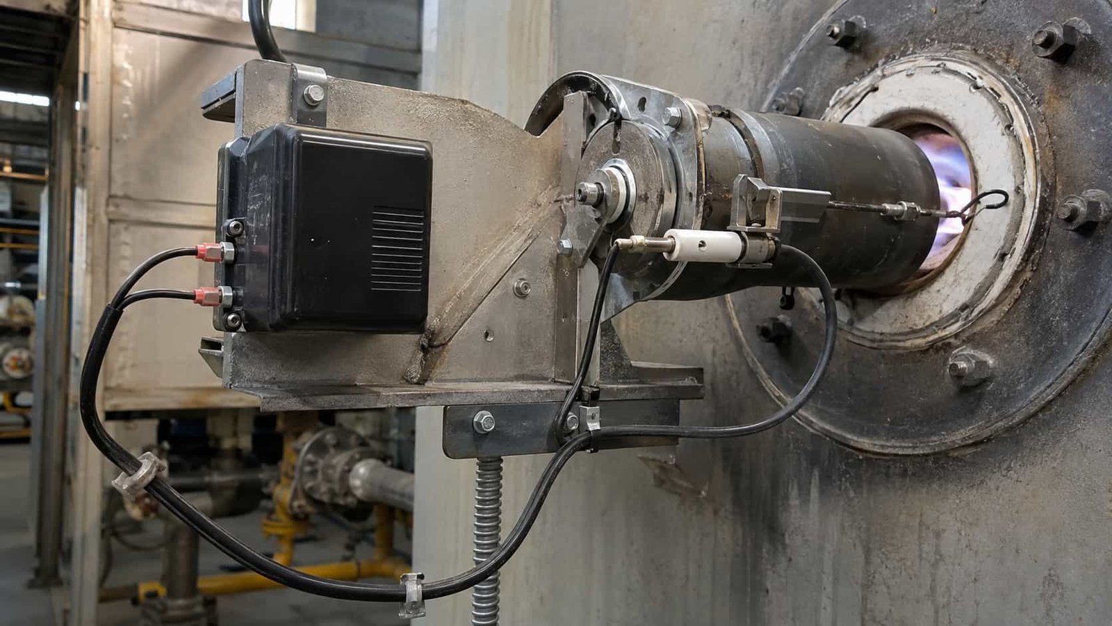
Dónde se utiliza
- Incendiadores industriales — calentadores de proceso, reformadores, hornos y hornos usando chispa-rod ignición.
- Ignición de caldera y paquete — gas y fuego de petróleo, incluyendo ignífugos retráctil.
- Turbina de gas e igniters de células de prueba de motor — cortos, conteo de ciclos altos, ambiente alto.
- Encendedores de incineradores y oxidadores térmicos — el caso clásico para la construcción de 538 °C.
- Pilotos de fuego - donde el ignífugo se sienta en la punta en lugar de en el grado. Para el largo recorrido por la pila, vea cable de encendido para antorcha.
- Sistemas de encendido de alta energía (HEI) — exciteres de descarga capacitiva alimentando un ignífugo de haz superficial o de aire.
¿Cuál de las dos construcciones que necesitas?
Esta es la única decisión en esta página que importa, y gira en la temperatura del conductor en el extremo terminal - no el ambiente en la casa de quemadores, y ciertamente no la temperatura de la llama.
| Si el conductor de la barra ve... | Comprar | Porque... |
|---|---|---|
| Hasta 250 °C | Fluoropolímero, UL AWM 1911 | Un cuarto del diámetro, un radio de curva real más ajustado, una mejor resistencia al aceite y al solvente, un número de estilo listado y más barato |
| 250 °C a 538 °C | Mica / fibra de vidrio | Ningún polímero dieléctrico sobrevive sobre 260 °C continuamente; el aislamiento tiene que ser inorgánico |
| No lo sabes. | Medida antes de comprar | Comprar el 538 °C construir “para estar seguro” significa cuatro veces el diámetro, una ruta más rígida y una glándula más grande para un margen que puede no necesitar |
La sobreescritura aquí no es gratis. La construcción de mica es más voluminosa, más rígida y más querida, y en un ignífugo apretado el diámetro extra puede ser la razón por la que no cabe el conducto que ya tiene.
Donde el cable de encendido falla
- En el empalme, cada vez. Un empalme de campo en un plomo de 25 kV es un punto débil fabricado — la descarga lo encontrará antes de que encuentre la varilla. Ordenar la longitud de ejecución y terminar en ambos extremos correctamente; no te unes a dos cortes.
- Al final de la terminal, por calor no presupuestaste. La varilla conduce el calor de nuevo en el plomo. Si el último 300 mm está decolorado o el trenzado se ha debilitado, la temperatura del conductor está por encima de lo que especificó.
- De la humedad en la mica. Mica húmeda deja de aislar. Mantener el carrete sellado, cortar sólo lo que necesitas, y terminar el extremo del corte el mismo día.
- De una curva que rompió la envoltura. En el mica construir un kink puede fracturar la envoltura sin marcar el trenzado. Pasará un control visual y fallará meses después como un fuego intermitente.
- De tratar el trenzado como una pantalla. La unión de la trenza de fibra de vidrio no hace nada eléctricamente y puede engañar al siguiente técnico para pensar que el circuito está proyectado.
Para qué no sirve este cable
- No es un motor o un plomo pequeño. En 7–10 kV use Cable de encendido de silicona de 7–10 kV o Style 3304 / 3573 10 kV, cable de encendido. Pagar por 25 kV y 538 °C en una pista de genset es dinero gastado en nada.
- No equipo interno HV cableado. Para cables dentro de un armario o un conjunto de imágenes o pruebas, use cable de silicona de alta tensión en UL 3239 o UL 10475.
- No es un cable de conexión general 538 °C. El cable de conexión de mica y vidrio a 300–600 V es un producto diferente y mucho más fino; no compre un cable de 25 kV para cablear una caja de terminales de horno.
- No es un cable de alta tensión apantallado. Sin pantalla, sin cable de drenaje, por diseño.
- No es una pista de termopar o ignífugo. La prueba de llama es un circuito separado con su propio cable.
Los cables de conexión de equipos en zonas calientes a 300 V requieren una construcción distinta de la de este cable de encendido, como el cable de mica-vidrio UL 5390 con valores nominales de 550°C y 300 V AC para el cableado interno de equipos.
Los dos construyen lado a lado
| Propiedad | Construcción mica/fibra de vidrio | Fluoropolímero de construcción |
|---|---|---|
| Temperatura máxima del conductor | 538 °C (1,000 °F) | 250 °C (482 °F) |
| Tensión nominal | 25 kV DC / 17 kV AC | 25 kV DC / 17 kV AC |
| tipo UL AWM | Ninguno - construcción de fábrica | Estilo 1911 |
| Conductor | Cobre finamente trenzado niquelado | Cobre finamente trenzado niquelado |
| Tamaño estándar | 18 AWG (16/30 hilos) | 18 AWG (19 hilos) |
| Aislamiento | Cinta multicapa con barrera de humedad | Fluopolímero extruido |
| Cubierta | Trenza de fibra de vidrio impregnada | El fluoropolímero es la chaqueta |
| Pantalla | Ninguno | Ninguno |
| Típico OD | 8.6 mm (0.339 in) | 2.49 mm (0.098 in) |
| Peso típico | 75 kg/km | 16 kg/km |
| Radio de curvatura, estático | 6 × OD (sobre 52 mm) | 12 × OD (sobre 30 mm) |
| Radio de curvatura, dinámico | 8 × OD (sobre 69 mm) | 15 × OD (sobre 37 mm) |
| Resistencias | Calor, flexión | Calor, flexión, químicos, abrasión |
Fluoropolímero de construcción — tamaños y clases de tensión
La construcción UL AWM 1911 es la que escala, porque la pared se extruye y se puede simplemente hacer más gruesa para una clase superior. Dimensiones típicas terminadas:
| Clase | AWG | Hilos | OD típico (mm) | OD típico (in) | Peso típico (kg/km) |
|---|---|---|---|---|---|
| 10 kV DC | 24 | 7 | 1.56 | 0.062 | 5.7 |
| 10 kV DC | 22 | 7 | 1.73 | 0.068 | 7.5 |
| 10 kV DC | 20 | 7 | 1.90 | 0.075 | 9.6 |
| 10 kV DC | 18 | 19 | 2.08 | 0.082 | 12.6 |
| 25 kV DC | 20 | 7 | 2.30 | 0.091 | 12.5 |
| 25 kV DC | 18 | 19 | 2.49 | 0.098 | 15.9 |
| 30 kV DC | 20 | 7 | 2.51 | 0.099 | 14.2 |
| 30 kV DC | 18 | 19 | 2.69 | 0.106 | 17.7 |
Lea la tabla abajo una columna, no al otro lado. Un conductor de 18 AWG aparece en 10, 25 y 30 kV y es el mismo conductor cada vez — 2.08, 2.49 y 2.69 mm de diámetro acabado es el crecimiento de la pared, no el cobre. Tamaños actuales del conductor; voltaje tamaño la pared. Subir dos clases de kV en el mismo 18 AWG cuesta 0.6 mm de diámetro y alrededor de 5 kg/km, y esa es la diferencia completa.
Construcción mica/fibra de vidrio — tamaños
18 AWG en 8.6 mm es la oferta estándar y cubre la gran mayoría del servicio de encendido. Otros tamaños de conductor se hacen para ordenar; porque el recuento de envoltura y trenzado están fijados por la clase de voltaje en lugar del conductor, el diámetro acabado no escala la forma en que un alambre extruido lo hace. Acabado OD y peso para un tamaño no estándar se confirman en el dibujo de la construcción antes de la producción.
Común a ambos
| Propiedad | Valor |
|---|---|
| Conductores | Unipolar, sin pantalla |
| Recubrimiento del conductor | Níquel |
| Longitud | Hecho para correr la longitud; suministrado como una pieza continua, no espiada |
| Prueba de rutina | Prueba de voltaje aplicada en cada longitud de producción, registro suministrado |
| Terminaciones | Anillos, botas y conjuntos de glándulas ajustados y probados bajo petición |
Lo que cubre cada construcción
| Referencia | Alcance | Cómo se aplica aquí |
|---|---|---|
| Estilo UL AWM 1911 | Material de cableado de alta tensión: cobre niquelado, fluoropolímero aislado, 250 °C, valorado a 25 kV DC y superior | Cubre la fluoropolímero de construcción en esta página. Si su especificación requiere un número de estilo listado, éste es el que debe escribir. |
| — (sin estilo AWM) | Cinta de Mica + barrera de humedad + trenza de fibra de vidrio impregnada en 25 kV | El La construcción de 538 °C tiene clasificación de fábrica. Ningún estilo de AWM describe una ventaja de alto voltaje de mica y vidrio, por lo que compare en el recuento de capas y la envoltura, no en un número. |
| UL AWM estilos de mica-glass (5107, 5128 y similares) | Mica y vidrio enganche alambre, normalmente 300–600 V en 450–538 °C | Los mismos materiales. trabajo diferente. Estos son estilos de cableado de cajas de terminales y hornos, no cables de encendido de 25 kV. Cotizar uno para servicio de encendido sería un error de categoría. |
| RoHS | Sustancias restringidas | Ambas construcciones son compatibles con RoHS. |
| Ensayo rutinario de tensión aplicada | Ensayo de fábrica en cada longitud producida | Cada longitud se prueba con tensión antes del despacho y el registro se envía con el carrete. |
17 kV AC aquí, 10 kV AC en el cable de bengala — el mismo 25 kV DC
Ambos productos son 25 kV DC, y los compradores razonablemente asumen que las cifras de AC también coinciden. No lo hacen, y la razón es la dieléctrica. Un sistema de mica envuelto y una pared extrusionada de fluoropolímeros mantienen una cresta 25 kV DC cómodamente, y ambos sostienen 17 kV AC; una gruesa pared de silicona del tipo utilizado en cable de encendido para antorcha valorado 10 kV AC para la misma clase DC. El estrés de la frecuencia eléctrica sostenida es un deber diferente de una cresta de descarga, y es el número que separa productos similares. Si su transformador de encendido produce un arco AC continuo en lugar de una descarga capacitiva, la figura AC es la que decide su compra — compruebe antes de comparar precios.
Lo que un número de estilo no te dice
Style 1911 fija el material, la temperatura y la clase de tensión. No fija el varado, el porcentaje de plateo, la concentricidad de la pared, o cómo el alambre se comporta después de dos mil ciclos térmicos junto a un quemador. Dos citas que dicen “UL 1911, 25 kV, 18 AWG” pueden ser alambres muy diferentes. Pida la varilla y la placa, y pida el dibujo de la construcción antes que después del pedido.
Qué necesitamos de usted para cotizar
- Temperatura del conductor en el extremo terminal - medidos si es posible; esto solo elige la construcción
- Producto transformador o estimulante: DC o AC, y la figura kV
- Ejecutar la longitud entre transformador y varilla, y si está en conducto
- Detalles de terminación en ambos extremos: tamaño de la barra, tipo de la lug, bota, hilo de la glándula
- Cuento del ciclo y si el plomo se mueve en el servicio - los encendidos retráctil son un deber flexible
Certificación TEBAOFLEX
Jiangsu TEBAOFLEX Special Cable Co., Ltd posee el certificado UL UL-US-2449012-0 y el certificado cUL UL-CA-2437036-0, ambos de fecha 27 de diciembre de 2024 según el informe E542560-20241225, y el certificado VDE 40060055 de fecha 28 de marzo de 2025. Son certificaciones de la empresa. Envíe la construcción, la clase de kV y el tamaño que desea pedir y confirmaremos el alcance de aprobación aplicable antes de que se comprometa.
Documentación suministrada con un pedido
- Plano de construcción con OD acabado y peso confirmados para la construcción y el tamaño acordados
- Registros de ensayos rutinarios del lote de producción, incluido el ensayo de tensión aplicado
- Certificado de conformidad que referencia la construcción y los valores nominales acordados
- Carrete y lista de embalaje con marcación y longitud del recorrido
Para conocer el alcance de una norma concreta, consulte directamente al organismo emisor — UL Solutions para estilos de AWM.
Opciones de cable relacionadas
Compare estas opciones de cable según la combinación de funciones, el movimiento, la carga, la tensión y los requisitos de transmisión.
Cable de encendido para antorcha 25 kV CC / 10 kV CA, 250°C
Una opción de cable relacionada para una aplicación o perfil de trabajo diferente.
Ver producto
Cable de encendido de silicona 7/10 kV
Una opción de cable relacionada para una aplicación o perfil de trabajo diferente.
Ver producto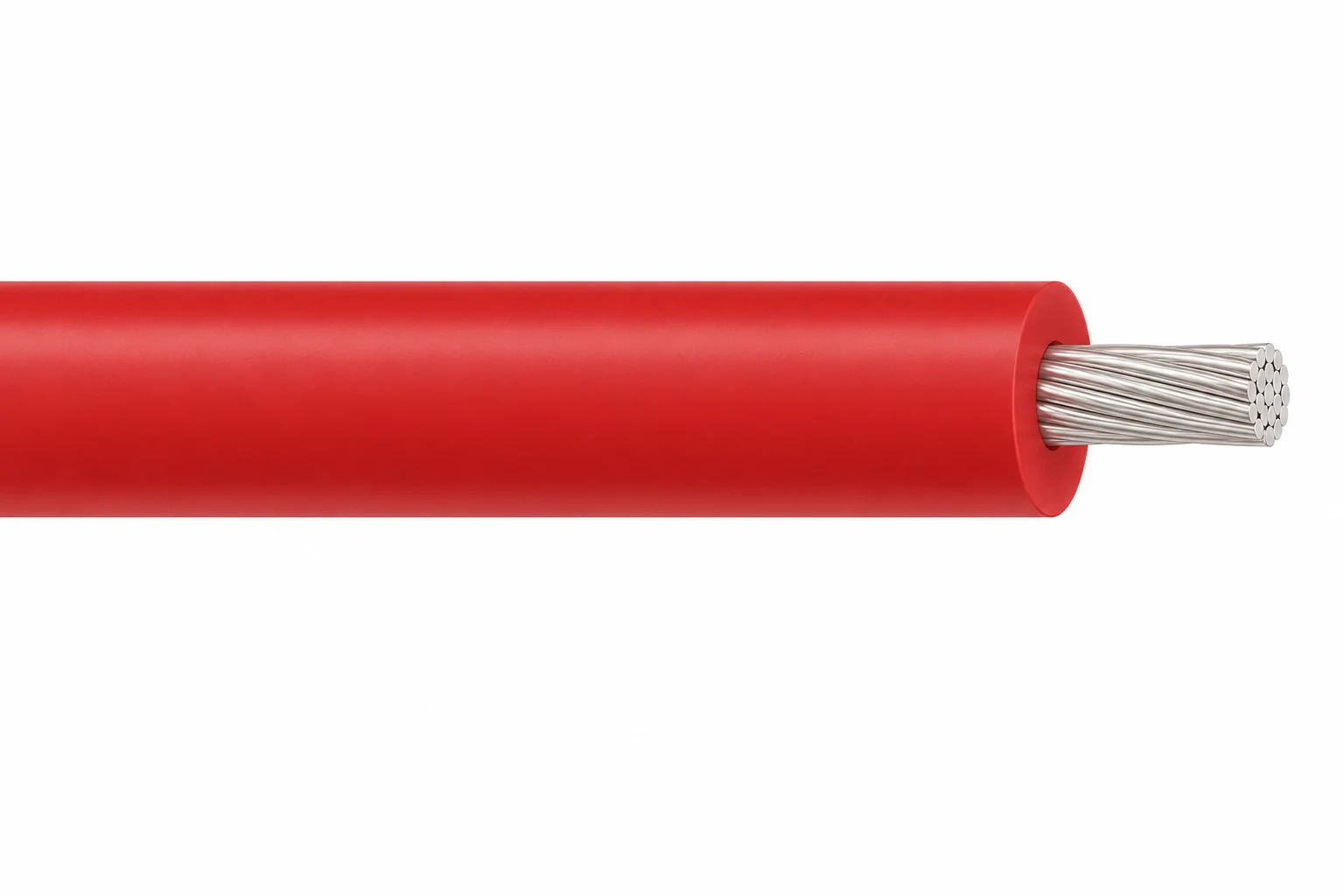
Cable de silicona de alta tensión, 3–60 kV DC
Una opción de cable relacionada para una aplicación o perfil de trabajo diferente.
Ver productoSolicite una recomendación y una cotización de cables.
Indique las funciones requeridas, la longitud del cable, las exigencias mecánicas, el entorno, el tipo de terminación y la cantidad. Nuestro equipo revisará la aplicación antes de preparar la cotización.
- Incluya el nombre del producto o SKU, así como la longitud y la cantidad de cable requeridas.
- Adjunte una especificación, un dibujo o una hoja de datos cuando esté disponible.