





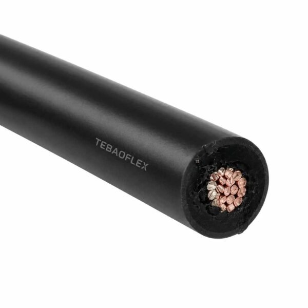
Fil d’allumage haute tension 25 kV, 250°C et 538°C
Fil d’allumage 25 kV en deux constructions : mica/fibre de verre jusqu’à 538 °C et fluoropolymère jusqu’à 250 °C. Unipolaire sans écran, fabriqué à la longueur du parcours.
- Valeurs nominales : 25 kV DC / 17 kV AC, les deux constructions
- Construction 538 °C : bande de mica multicouche + barrière d'humidité sous tresse en fibre de verre imprégnée
- Construction 250 °C : fluoropolymère extrudé, Style UL AWM 1911
- Conducteur : cuivre nickelé finement échoué, norme 18 AWG
- OD typique: 8.6 mm (538 °C) / 2.49 mm (250 °C)
- Rayon de courbure : 6 × OD statique (538 °C) / 12 × OD statique (250 °C)
- Écran : aucun — non vérifié par le dessin ou modèle
Envoyez la configuration, la section et la longueur requises pour obtenir un devis technique.
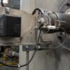
Le fil d’allumage est le plomb entre le transformateur ou l'excitateur d'allumage et la tige d'étincelle, et il vit au pire endroit dans le quartier de la chambre de combustion. TEBAOFLEX le construit à 25 kV DC / 17 kV AC dans deux constructions qui partagent la classe de tension et rien d'autre:
A Construction mica/fibre de verre, classée à 538 °C (1 000 °F), où l'isolation est inorganique parce qu'aucun polymère ne survit là-haut - ruban mica multicouche avec une barrière d'humidité sous une tresse en fibre de verre imprégnée. Et une construction de fluoropolymère 250 °C dans Style UL AWM 1911, qui échange le haut de la plage de température pour un fil moins d'un tiers du diamètre et beaucoup mieux résistance à l'huile, solvant et abrasion.
Les deux utilisent du cuivre nickelé finement échoué, les deux sont des noyaux simples non à écran, et les deux sont faits à la longueur de fonctionnement entre votre transformateur et votre tige. Celui dont vous avez besoin est déterminé par un numéro: la température que le conducteur atteint effectivement à l'extrémité terminale, et non la température ambiante, et non la température de la flamme.
Ceux-ci ont une classe au-dessus du moteur 7–10 kV et le brûleur mène ailleurs dans notre gamme, et au-dessus câble d’allumage de torchère, qui est 25 kV DC mais seulement 10 kV AC et 250 °C. Pour l'image complète du matériau et de la température, voir matrice de sélection des fils haute température et le reste des câble haute température gamme.
Envoyez la température du conducteur à la tige, la sortie du transformateur et la longueur d'exécution, et nous vous indiquerons laquelle des deux vous devriez acheter, y compris lorsque la réponse est la moins chère.
Deux constructions, une classe de tension. Le conducteur et le travail sont identiques; le système d'isolation est là où ils se séparent de l'entreprise, et ce choix détermine le diamètre, la rigidité et le prix.
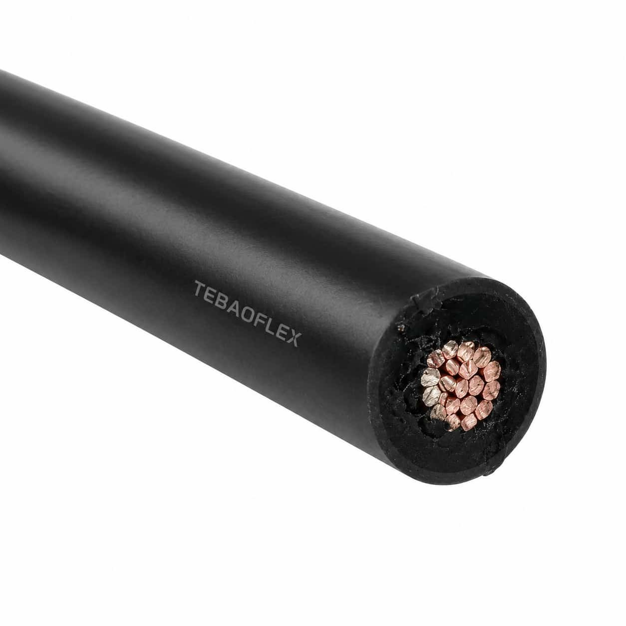
Construction 538 °C : mica et verre
- Conducteur : finement toronné cuivre nickelé, 18 AWG standard. Le nickel n'est pas une préférence à cette température, c'est le seul plat commun qui le survit.
- Isolation : bande de mica multicouchesEnveloppé hélico. Mica est un minéral, pas un polymère — c'est tout le point. A 538 °C il n'y a plus de plastique à fondre parce qu'il n'y a jamais eu de plastique faisant l'isolation.
- Barrière d'humidité: une mince Barrière PTFE dans l'emballage. Une faiblesse de Mica est qu'il prendra l'humidité, et mica humide n'est pas un isolant. La barrière protège l'enveloppe pendant le stockage, l'installation et le lavage.
- Gaine : une tresse de fibre de verre imprégnée, fini de sorte qu'il ne fraye pas quand il est coupé et terminé.
Construction 250 °C : fluoropolymère, UL AWM Style 1911
- Conducteur : le même cuivre nickelé finement échoué.
- Isolation : extrudé fluoropolymère, qui est à la fois le diélectrique et la veste. Une couche fait tout.
C'est toute la construction, et c'est pourquoi cette version est une fraction du diamètre. Il porte aussi une UL Numéro de style AWM, que la construction mica ne peut pas, parce qu'aucun style AWM décrit une construction mica-et-verre haute tension.
Pourquoi le chaud est plus gras et le frais est plus mince
La bande Mica doit être enveloppée, non extrudée, et un diélectrique enveloppé a besoin de beaucoup plus de tours pour atteindre la même résistance qu'un extrudé a besoin de millimètres. Ajouter la tresse de verre et le 538 °C construire des terrains à peu près 8.6 mm sur un conducteur de 18 AWG. La version fluoropolymère atteint les mêmes 25 kV DC dans 2.49 mm. Même conducteur, même tension, trois fois et demie le diamètre — et chaque morceau de cette différence est le prix de la 288 °C supplémentaire.
Rayon de courbure : multipliez avant de comparer
La construction 538 °C est spécifiée à 6 × OD statique, 8 × OD dynamique. La construction de fluoropolymère est 12 × OD statique, 15 × OD dynamique. Lisez comme des multiplicateurs, le chaud semble deux fois plus flexible. Ça ne l'est pas. Multipliez les valeurs : 6 × 8,6 mm donne un 52 mm rayon statique; 12 × 2.49 mm est 30 mm. Le fil mince franchit encore le coude le plus serré avec une large marge. Les multiplicateurs de rayon de courbure ne se comparent qu’au sein d’une même construction; entre constructions, ils sont trompeurs, et c’est précisément le couple qui piège souvent.
Pas d'écran, et c'est délibéré
Aucune des deux constructions n'a d'écran métallique ou de fil de drainage. Sur un circuit d'allumage 25 kV un écran est quelque part pour que la décharge aller ce n'est pas la tige. La tresse en fibre de verre sur la construction chaude est mécanique et thermique; ne le lie pas et ne le termine pas comme un bouclier.
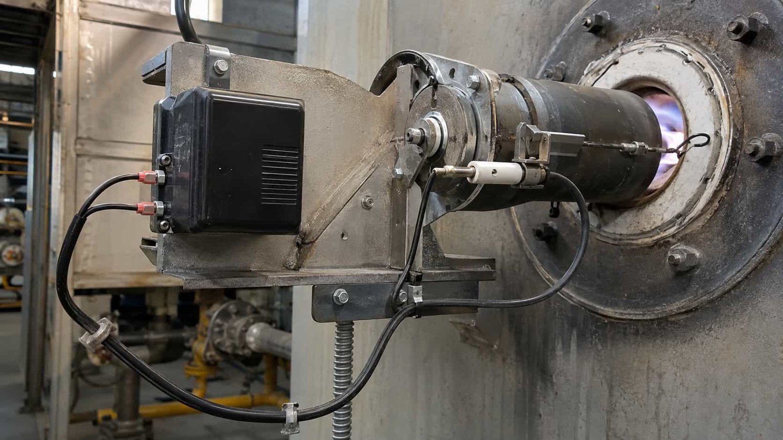
Le fil d’allumage a un devoir et il est impitoyable: livrer une étincelle à une tige qui est assise à côté ou à l'intérieur d'une flamme. Tout sur cette page suit la température que le conducteur atteint à cette fin.
Où il est utilisé
- Brûleurs industriels — chauffages, reformeurs, fours et fours à étincelles.
- Allumage des chaudières et des chaudières — au gaz et au pétrole, y compris les allumeurs rétractables.
- Allumeurs à turbine à gaz et à pile à moteur — à court terme, à cycle élevé, à environnement élevé.
- Allumeurs d’incinérateurs et d’oxydateurs thermiques — le cas classique de la construction 538 °C.
- Pilotes à flammes — où l'allumeur se trouve à l'extrémité plutôt qu'au niveau. Pour le long terme de la pile, voir câble d’allumage de torchère.
- Systèmes d'allumage à haute énergie (HEI) — les excitateurs à décharge capacitive alimentant un enflammeur à gap de surface ou à gap d'air.
Laquelle des deux constructions vous avez besoin
C'est la seule décision sur cette page qui compte, et il tourne sur le température du conducteur à l'extrémité du terminal — pas l'ambiance de la maison du brûleur, et certainement pas la température de la flamme.
| Si le conducteur voit... | Acheter | Parce que |
|---|---|---|
| Jusqu'à 250 °C | Fluoropolymère, UL AWM 1911 | Un quart de diamètre, un rayon de courbure plus serré, une meilleure résistance à l'huile et au solvant, un numéro de style listé, et moins cher |
| 250 °C à 538 °C | Mica / fibre de verre | Aucun diélectrique polymère ne survit au-dessus de 260 °C en continu; l'isolation doit être inorganique |
| Tu ne sais pas | Mesurez avant d'acheter | Acheter la construction 538 °C pour être sûr signifie quatre fois le diamètre, une route plus raide et une glande plus grande pour une marge que vous n'avez pas besoin |
Ce n'est pas gratuit. La construction de mica est plus volumineuse, plus rigide et plus chère, et sur un ensemble d'allumeurs serrés le diamètre supplémentaire peut être la raison pour laquelle il ne correspond pas à la conduite que vous avez déjà.
Lorsque le fil d’allumage échoue
- À chaque fois. Un brin de champ sur une tête 25 kV est un point faible fabriqué — la décharge le trouvera avant qu'il trouve la tige. Commandez la longueur de course et terminez correctement aux deux extrémités; ne joignez pas deux coupures.
- À l'extrémité terminale, de la chaleur que vous n'avez pas bu. La tige conduit la chaleur à nouveau dans le plomb. Si la dernière 300 mm est décolorée ou si la tresse est devenue fragile, la température du conducteur est supérieure à ce que vous avez spécifié.
- De l'humidité dans le mica. Mica humide arrête d'isoler. Gardez la bobine scellée, couper seulement ce dont vous avez besoin, et terminer la fin de la coupe le même jour.
- D'un virage qui a cassé l'enveloppe. Sur le mica construire une crique peut fracturer l'enveloppe sans marquer la tresse. Il passera une vérification visuelle et échouera des mois plus tard comme un faux feu intermittent.
- De traiter la tresse comme un écran. Le collage de la tresse en fibre de verre ne fait rien électriquement et peut induire en erreur le prochain technicien en pensant que le circuit est filtré.
Ce à quoi ce fil n'est pas destiné
- Pas un moteur ou un plomb de petit brûleur. À l'utilisation de 7–10 kV Câble d’allumage silicone 7–10 kV ou Style 3304 / 3573 10 kV, fil d’allumage. Payer pour 25 kV et 538 °C sur une avance de genset est de l'argent dépensé sur rien.
- Pas de câblage HV interne. Pour les fils à l'intérieur d'une armoire ou d'un ensemble d'imagerie ou de test, utiliser câble silicone haute tension en UL 3239 ou UL 10475.
- Pas un câble 538 °C général. Le fil de raccordement mica-verre à 300–600 V est un produit différent et beaucoup plus fin; n’achetez pas un fil de 25 kV pour câbler une boîte à bornes de four.
- Ce n’est pas un câble haute tension blindé. Pas d'écran, pas de fil de drainage, par conception.
- Pas un thermocouple ou une tige de flamme. La flamme est un circuit séparé avec son propre câble.
Les fils d'équipements en zone chaude à 300 V exigent une construction différente de ce fil d'allumage, par exemple le fil mica-verre UL 5390 aux valeurs nominales de 550°C et 300 V AC pour le câblage interne des équipements.
Les deux construisent côte à côte
| Propriété | Construction mica/fibre de verre | Construction de fluoropolymère |
|---|---|---|
| Température maximale du conducteur | 538 °C (1 000 °F) | 250 °C (482 °F) |
| Tension assignée | 25 kV DC / 17 kV AC | 25 kV DC / 17 kV AC |
| type UL AWM | None — constructions classées en usine | Style 1911 |
| Conducteur | Cuivre finement toronné nickelé | Cuivre finement toronné nickelé |
| Taille standard | 18 AWG (16/30 brins) | 18 AWG (19 brins) |
| Isolation | Bande de mica multicouche avec barrière d'humidité | Fluopolymère extrudé |
| Gaine | Tresse de fibre de verre imprégnée | Le fluoropolymère est la veste |
| Écran | Aucun | Aucun |
| OD typique | 8.6 mm (0.339 in) | 2.49 mm (0.098 in) |
| Poids typique | 75 kg/km | 16 kg/km |
| Rayon de courbure, statique | 6 × OD (environ 52 mm) | 12 × OD (environ 30 mm) |
| Rayon de courbure, dynamique | 8 × OD (environ 69 mm) | 15 × OD (environ 37 mm) |
| Résiste | Chaleur, flexion | Chaleur, flexion, produits chimiques, abrasion |
Construction de fluoropolymère — tailles et classes de tension
La construction UL AWM 1911 est celle qui écaille, parce que le mur est extrudé et peut simplement être rendu plus épais pour une classe supérieure. Dimensions de finition typiques:
| Classe | AWG | Brins | OD typique (mm) | OD typique (in) | Poids typique (kg/km) |
|---|---|---|---|---|---|
| 10 kV DC | 24 | 7 | 1.56 | 0.062 | 5.7 |
| 10 kV DC | 22 | 7 | 1.73 | 0.068 | 7.5 |
| 10 kV DC | 20 | 7 | 1.90 | 0.075 | 9.6 |
| 10 kV DC | 18 | 19 | 2.08 | 0.082 | 12.6 |
| 25 kV DC | 20 | 7 | 2.30 | 0.091 | 12.5 |
| 25 kV DC | 18 | 19 | 2.49 | 0.098 | 15.9 |
| 30 kV DC | 20 | 7 | 2.51 | 0.099 | 14.2 |
| 30 kV DC | 18 | 19 | 2.69 | 0.106 | 17.7 |
Lisez le tableau dans une colonne, pas en face. Un conducteur 18 AWG apparaît à 10, 25 et 30 kV et il est le même conducteur à chaque fois — 2.08, 2.49 et 2.69 mm de diamètre fini est la croissance de la paroi, pas le cuivre. Tailles du courant du conducteur; la tension dimensionne le mur. Monter deux classes de kV sur la même 18 AWG coûte 0.6 mm de diamètre et environ 5 kg/km, et c'est toute la différence.
Construction mica/fibre de verre — dimensions
18 AWG à 8.6 mm est l'offre standard et couvre la grande majorité des fonctions d'allumeur. D'autres tailles de conducteurs sont réalisées sur commande; parce que le nombre d'enveloppes et la tresse sont réglés par la classe de tension plutôt que par le conducteur, le diamètre fini ne fait pas l'échelle comme le fait un fil extrudé. Le OD fini et le poids pour une taille non standard sont confirmés sur le dessin de construction avant la production.
Fréquent aux deux
| Propriété | Valeur |
|---|---|
| Âmes | Unipolaire, sans écran |
| Placage du conducteur | Nickel |
| Longueur | Fait pour la longueur de course; fournis en une seule pièce continue, non étirés |
| Essai de routine | Essai de tension appliqué sur chaque longueur de production, enregistrement fourni |
| Terminaisons | Raccords, bottes et ensembles de glandes montés et testés sur demande |
Ce qui couvre chaque construction
| Référence | Portée | Comment cela s’applique ici |
|---|---|---|
| Style UL AWM 1911 | Matériel de câblage pour appareils à haute tension: cuivre nickelé, fluoropolymère isolé, 250 °C, classé en 25 kV DC et au-dessus | Couvre la Construction de fluoropolymère sur cette page. Si votre spécification nécessite un numéro de style listé, c'est celui à écrire. |
| — (sans style AWM) | Bande de mica + barrière d'humidité + tressée en fibre de verre imprégnée à 25 kV | Le La construction 538 °C est classée en usine. Aucun style AWM ne décrit un plomb mica et verre à haute tension, alors comparez-le sur le nombre de couches et l'enveloppe, pas sur un nombre. |
| Modèles UL AWM mica-glass (5107, 5128 et similaires) | Mica et verre Raccordement fil, généralement 300–600 V à 450–538 °C | Mêmes matériaux, travail différent. Ce sont des modèles de câblage de la boîte de terminal et du four, pas des fils d'allumage 25 kV. devis d'un pour la fonction allumeur est une erreur de catégorie. |
| RoHS | Substances réglementées | Les deux constructions sont fournies conforme à RoHS. |
| Essai de tension appliquée de routine | Essai en usine sur chaque longueur produite | Chaque longueur est soumise à un essai de tension avant expédition et le procès-verbal accompagne le touret. |
17 kV AC ici, 10 kV AC sur le câble de la pile de fusée — même 25 kV DC
Les deux produits sont 25 kV DC, et les acheteurs supposent raisonnablement que les chiffres de AC correspondent aussi. Ils ne le font pas, et la raison est le diélectrique. Un système de mica enveloppé et une paroi en fluoropolymère extrudée tiennent une crête 25 kV DC confortablement, et les deux tiennent 17 kV AC; une paroi en silicone épaisse du type utilisé sur câble d’allumage de torchère est noté 10 kV AC pour la même classe DC. La contrainte de puissance-fréquence soutenue est un devoir différent d'une crête de décharge, et c'est le nombre qui sépare les produits autrement similaires. Si votre transformateur d'allumage produit un arc AC continu plutôt qu'une décharge capacitive, le chiffre AC est celui qui décide de votre achat — vérifiez-le avant de comparer les prix.
Ce qu'un numéro de style ne vous dit pas
Style 1911 fixe le matériau, la température et la classe de tension. Il ne fixe pas l'échouement, le pourcentage de placage, la concentricité de la paroi, ou comment le fil se comporte après deux mille cycles thermiques à côté d'un brûleur. Deux citations disant toutes deux UL 1911, 25 kV, 18 AWG sont des fils très différents. Demandez l'échouement et le placage, et demandez le dessin de construction avant l'ordre plutôt qu'après.
Ce dont nous avons besoin pour établir un devis
- Température du conducteur à l'extrémité terminale — mesurés si possible; ce seul choisit la construction
- Sortie du transformateur ou de l'excitateur: DC ou AC, et la figure kV
- Longueur entre le transformateur et la tige, et si elle est dans le conduit
- Détails de résiliation aux deux extrémités: taille de tige, type de lubrification, botte, fil de glande
- Nombre de cycles et si le plomb se déplace en service — allumeurs rétractables sont une fonction de flex
Certification TEBAOFLEX
Jiangsu TEBAOFLEX Special Cable Co., Ltd détient le certificat UL UL-US-2449012-0 et le certificat cUL UL-CA-2437036-0, tous deux datés du 27 décembre 2024 selon le rapport E542560-20241225, ainsi que le certificat VDE 40060055 daté du 28 mars 2025. Il s’agit de certifications au niveau de l’entreprise. Envoyez la construction, la classe de kV et la section envisagées; nous confirmerons le périmètre d’approbation applicable avant votre engagement.
Documentation fournie avec une commande
- Plan de construction indiquant l’OD fini et le poids confirmés pour la construction et la section convenues
- Procès-verbaux des essais de routine du lot de production, y compris l’essai de tension appliqué
- Certificat de conformité faisant référence à la construction et aux caractéristiques convenues
- Touret et liste de colisage avec marquage et longueur du parcours
Pour le périmètre d’une norme donnée, consultez directement l’organisme émetteur — UL Solutions pour les styles AWM.
Options de câbles associées
Comparez ces options de câbles selon les fonctions requises, le mouvement, la charge, la tension et les besoins de transmission.
Câble d'allumage et d'allumeur de torchère 25 kV CC / 10 kV CA, 250°C
Une autre option de câble pour une application ou des conditions de service différentes.
Voir le produit
Câble d’allumage silicone 7/10 kV
Une autre option de câble pour une application ou des conditions de service différentes.
Voir le produit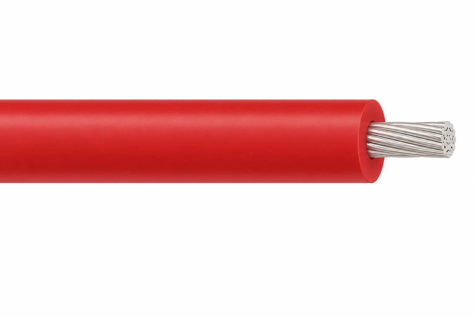
Fil haute tension silicone, 3–60 kV DC
Une autre option de câble pour une application ou des conditions de service différentes.
Voir le produitDemandez une recommandation et un devis pour un câble.
Indiquez les fonctions requises, la longueur du câble, les contraintes mécaniques, l’environnement, les terminaisons et la quantité. Notre équipe évaluera l’aptitude à l’application avant d’établir une soumission.
- Veuillez inclure le nom du produit ou son SKU, ainsi que la longueur et la quantité de câble requises.
- Joignez une fiche technique, un dessin ou une fiche de spécifications si disponible.