
Underwater sensor & control cable engineering
Armoured Underwater Instrumentation Cables
Single-core and multicore load-bearing cable routes for underwater sensors, CTD packages, monitoring equipment and compact control circuits. Select the construction by electrical service, deployment load, bend duty, water exposure and termination interface—not by core count alone.
Choose the engineering route first
What this cable family is designed to solve
An underwater instrumentation cable can be both the electrical link and part of the mechanical deployment system. A workable specification therefore joins signal or control requirements to the way the cable is suspended, recovered and terminated.
Routes for a compact single circuit or multicore sensor and control architecture.
Galvanized or AISI 316 stainless-steel armour selected around working load, breaking load and handling.
PVC, HDPE, PP, nylon, PET-E and hydrolysis-resistant PUR are applied by configuration.
Armour anchoring, sealing, connector geometry and strain relief are reviewed together.
A cable that carries its own weight, supports an instrument or cycles over a sheave needs a defined working load, safety approach, minimum bend radius and armour termination. These inputs can change the construction even when the conductor count remains the same.
Application map
Typical uses for underwater instrumentation cable
The same application name can hide very different loads and handling cycles. TEBAOFLEX uses the deployment method and equipment interface to narrow the cable route.
CTD and oceanographic instruments
For conductivity, temperature, depth and related sensor packages lowered from a vessel or platform. Define suspended mass, maximum payout, sheave geometry and wet-mate or dry-mate interface.
Coastal and subsea monitoring
For stationary or periodically recovered equipment where water exposure, jacket material, corrosion strategy and long-term termination sealing guide the design.
Winch-deployed sensors
For repeated payout and recovery. Dynamic bend radius, fleet angle, drum and sheave diameters, line pull and cycle profile should be reviewed before conductor or armour details are frozen.
Cameras and compact control circuits
For equipment that needs a small copper link with mechanical support. Voltage, current, conductor resistance, signal architecture and connector envelope remain project inputs.
Reference configuration comparison
Compare electrical and mechanical starting points
Use these configurations to identify the closest engineering route. The offered construction is then aligned with your voltage, load case, bend duty, environment, cable length and termination.
| Parameter | Miniature single-core | Seven-core stainless-steel | Seven-core PUR |
|---|---|---|---|
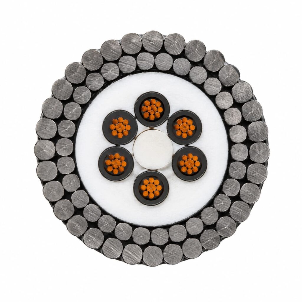
| Construction | 1 × 0.34 mm² copper; PVC insulation; nylon sheath; galvanized steel wire armour | 7 × 0.38 mm²; HDPE/nylon/PET-E; double contra-helical AISI 316 stainless-steel armour | 7 × 22 AWG; PP insulation; hydrolysis-resistant PUR; galvanized steel armour |
| Electrical value | 1000 Vdc × 1 min test | 300 V | 600 V |
| Nominal outer diameter | 3.15 mm | 9.20 mm | 9.10 mm |
| Breaking load | 6.33 kN | 3300 kg | 43 kN |
| Working load | — | 820 kg | 11 kN |
| Static bend radius | — | 135 mm | 95 mm |
| Dynamic bend radius | 75 mm | 180 mm | 190 mm |
| Temperature range | — | −40 to +80°C | −30 to +80°C |
Interpretation: 1000 Vdc × 1 min is a dielectric test value, not a continuous operating-voltage rating. Breaking load is not the allowable working load. A dash indicates that the parameter must be defined for the selected project construction.
Armour, load and handling
Select the armour around the complete deployment system
The armour material is only one part of the decision. Layer geometry, corrosion strategy, line pull, cycling and the way the armour is anchored at each end determine whether the load path works as intended.
Galvanized steel armour
A practical route where high mechanical capacity and compact construction are priorities. Water exposure, jacket coverage, galvanic interfaces and storage or maintenance conditions should be included in the corrosion review.
- Used in the miniature single-core and seven-core PUR references
- Review armour coverage and outer-jacket strategy
- Define termination anchoring and allowable line pull
AISI 316 stainless-steel armour
A corrosion-focused route for water-exposed instrumentation systems. The seven-core reference uses a double contra-helical armour arrangement to provide mechanical support around the electrical core.
- Used in the seven-core stainless-steel reference
- Confirm material compatibility at glands and connectors
- Define bending, cycling and tensile acceptance together
Handling definition
Static suspension and repeated recovery are different duties
Specification process
From equipment interface to quotation-ready cable definition
A short but structured input set lets engineering compare an existing configuration with a project-specific construction without blurring electrical, mechanical and environmental limits.
Equipment & route
Identify the instrument, installation, water exposure and deployed length.
Electrical service
Define circuits, voltage, current and the required signal or control architecture.
Mechanical duty
Provide working load, maximum line pull, bend geometry and handling cycles.
Materials & ends
Review armour, sheath, corrosion interfaces, connector and strain relief.
Offer & inspection
Align the proposed construction, drawing, test items and documentation.
Engineering and test references
References are applied to the relevant cable feature
Underwater load-bearing instrumentation cables are specified around the project duty. General cable standards can support individual conductor or material tests, while tensile, bend, water-exposure and termination acceptance remain part of the agreed inspection plan.
May be referenced for conductor class and resistance requirements where the selected design and project specification call for it.
Provides test-method references for insulation and sheath materials, with the applicable part selected for the required property.
Can define continuity, conductor resistance, dielectric test, dimensional checks, tensile or load checks, bend verification and documentation for the offered cable.
Conventional marine or process instrumentation cable standards primarily address installed electrical circuits. A cable that supports underwater equipment also needs an explicit mechanical load path, dynamic handling review and armour termination.
Buyer questions
Armoured instrumentation cable FAQ
How is this different from a normal shipboard armoured instrumentation cable?
A conventional shipboard cable is usually selected for a fixed installed circuit. An underwater load-bearing cable may also suspend or recover equipment, so working load, breaking load, bend radius, cycling, water exposure and armour termination become primary design inputs.
Should I choose galvanized or stainless-steel armour?
Choose from the full duty rather than corrosion resistance alone. Galvanized steel can support compact, high-capacity constructions; AISI 316 stainless steel can suit corrosion-focused water-exposed routes. The final choice also depends on sheath coverage, galvanic interfaces, cable geometry, cycling and termination hardware.
Is the stated breaking load the allowable working load?
No. Breaking load is not the allowable operating load. The project working load and safety approach must account for cable self-weight, equipment mass, payout length, currents, retrieval forces, dynamic effects and termination efficiency.
What information is needed for cable selection?
Send conductor count and size, voltage and current, signal or control description, cable length, water environment, equipment mass, working load or line pull, static and dynamic bend geometry, winch or sheave details, temperature range and termination requirements.
Can the cable be supplied for a connector or moulded termination?
The cable can be reviewed around the intended termination. Provide the connector or penetrator drawing, sealing concept, armour anchoring method, backshell envelope, strain-relief limits and required end preparation so the mechanical and water-blocking interfaces can be aligned.
Related engineering routes
Continue with the closest cable or application page
Request an engineering review
Define the cable around your instrument and deployment method
Send the load case and electrical requirements through the quotation form. Equipment drawings and connector files can be sent to the cable team by email for the same engineering review.