


Type 201 / Type 211 - Câble de traînage armé BS 6708, 640/1100 V
Câble minier Type 201 / Type 211 pour extensions de galerie de mine, traînage de carrière mécaniquement protégé et éclairage du front de taille, avec la classe 640/1100 V et la référence d'essai 2,5 kV définies par la source.
- Modèle : Type 201 / Type 211
- Conducteur et isolation : cuivre étamé flexible avec l'isolation et la construction d'âme indiquées pour ce modèle dans le PDF fourni
- Disposition d'écran, de pilote, de terre et d'armure conservée de la fiche technique source
- Protection extérieure en chloroprène ou PCP renforcé, telle qu'indiquée pour ce modèle
- Fiche technique originale du Type disponible en téléchargement produit
Envoyez l'équipement, la tension, la section du conducteur, l'itinéraire, la quantité et les exigences documentaires pour une demande de devis.
Type 201 / Type 211 pour extensions de galerie de mine, traînage de carrière mécaniquement protégé et éclairage du front de taille
Le câble minier Type 201 / Type 211 est spécifié dans la fiche technique BS 6708 fournie pour les extensions de galerie de mine, le traînage de carrière mécaniquement protégé et l'éclairage du front de taille.
La construction fournie utilise trois conducteurs de puissance flexibles en cuivre recuit étamé avec isolation MEPR et écrans de phase cuivre/nylon, armure souple en fil d'acier galvanisé et une gaine noire en PCP à bande jaune. Cette disposition compte car le Type 201 possède trois âmes de puissance blindées ; le Type 211 ajoute un conducteur de terre non blindé. Les deux utilisent l'armure et la gaine générale à bande jaune décrite dans le PDF. La famille doit donc être sélectionnée par modèle, fonction d'âme et itinéraire d'installation, en plus de la tension. gamme de câbles pour l'exploitation minière et le tunnelage offre le contexte produit plus large de TEBAOFLEX.
- Choisir par : confirmez si le Type 201 sans conducteur de terre ou le Type 211 avec un conducteur de terre non blindé correspond à l'équipement et au circuit de protection.
- Confirmez avant de commander : le marquage existant de la gaine, la section du conducteur, la longueur du câble, l'itinéraire, le système de support ou de manutention, les terminaisons et les documents d'inspection requis.
- Ne déduisez pas : des valeurs non indiquées dans le PDF fourni, telles qu'une base de courant différente, la performance à l'eau/l'huile/UV, la portée de certification ou l'interchangeabilité mécanique.
Lorsqu'un câble de traînage armé est remplacé, la Guide de remplacement des câbles miniers BS 6708 aide à conserver les vérifications de tension, d'armure et de famille de modèle dans la même revue.
Pour un devis technique, envoyez la plaque signalétique de l'équipement ou le marquage du câble existant, l'exigence de tension et de taille, les conditions d'installation, la quantité, la destination et toute exigence d'essai ou de documentation spécifique au projet.
Construction du Type 201 / Type 211
La coupe transversale ci-dessous est le schéma de construction fourni pour le Type 201 / Type 211. La décision de commande repose sur le fait que le Type 201 possède trois âmes de puissance blindées ; le Type 211 ajoute un conducteur de terre non blindé. Les deux utilisent l'armure et la gaine générale à bande jaune décrite dans le PDF.
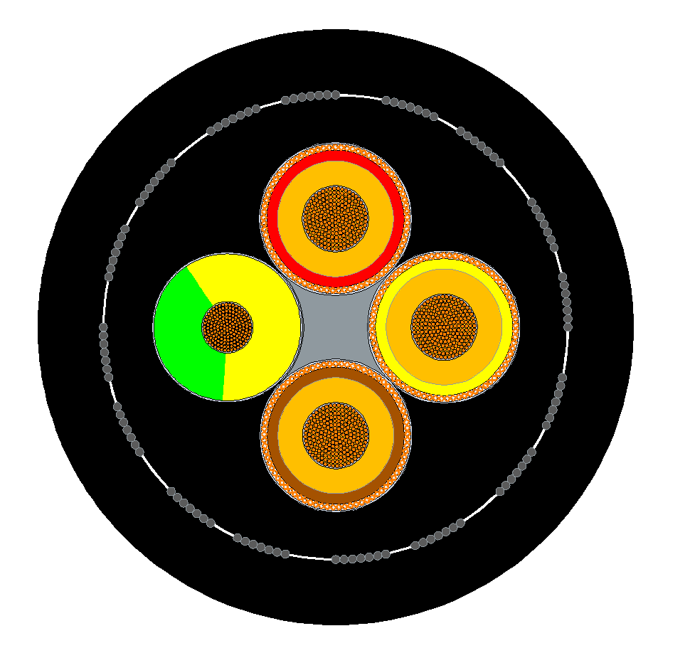
Construction indiquée par la source
| Élément de construction | Valeur indiquée par la source |
|---|---|
| Âmes d'alimentation | Trois conducteurs flexibles en cuivre recuit étamé, isolés MEPR et blindés cuivre/nylon |
| Type 201 | Trois âmes de puissance toronnées autour d'un centre de berceau élastomère |
| Type 211 | Trois âmes de puissance plus un conducteur de terre non blindé autour d'un centre élastomère |
| Garnissage | Gaine de bourrage PCP extrudée |
| Armure | Armure souple en fil d'acier galvanisé |
| Gaine générale | Composé élastomère ignifuge renforcé, PCP noir à bande jaune |
N'utilisez pas le schéma comme substitut aux tableaux dimensionnels. Confirmez la préparation de l'extrémité du câble, la terminaison de l'écran et de la terre, la mise à la masse de l'armure et l'interface machine avec la documentation de l'équipement avant l'installation.
Applications du Type 201 / Type 211
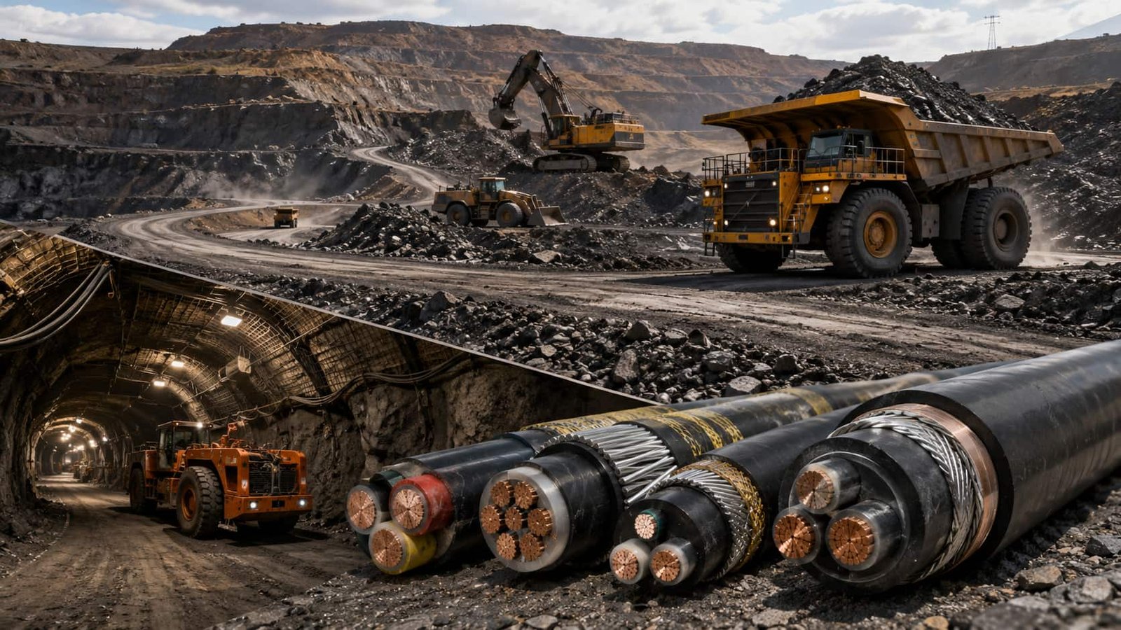
La fiche technique fournie identifie ce câble pour les extensions de galerie de mine, le traînage de carrière mécaniquement protégé et l'éclairage du front de taille.
- Service principal : extensions de galerie de mine, traînage de carrière mécaniquement protégé et éclairage du front de taille.
- Limite du modèle : Le Type 201 possède trois âmes de puissance blindées ; le Type 211 ajoute un conducteur de terre non blindé. Les deux utilisent l'armure et la gaine générale à bande jaune décrite dans le PDF.
- Vérification du projet : faites correspondre le marquage du câble, le plan des âmes, la tension, la terminaison, la géométrie de l'itinéraire et la méthode de manutention au schéma de la machine.
- Examen environnemental : confirmez les conditions réelles de la mine/carrière et toute exigence d'autorité, d'inspection ou de documentation ; ne déduisez pas une déclaration de certification ou de résistance des matériaux à partir du numéro de modèle.
Pour un itinéraire de traînage armé de 1900/3300 V, consultez le câble minier Type 321/331 famille comme comparaison de tension supérieure, sous réserve de la conception de l'équipement.
Le câble ne doit être libéré qu'après accord sur l'itinéraire de l'équipement, la longueur requise, la section du conducteur, les fonctions des âmes et les détails de connexion. Si le service prévu diffère de l'application indiquée par la source, demandez un examen d'ingénierie via le processus de devis.
Spécifications du Type 201 / Type 211
Le résumé ci-dessous identifie la famille de modèles fournie. Les tableaux transcrits de la source qui suivent conservent les valeurs dimensionnelles, électriques et de construction du PDF, y compris les tailles disponibles, la résistance, le courant, le diamètre, la masse et les données de courbure ou de traction lorsque le PDF les fournit.
| Élément de sélection | Valeur liée à la source |
|---|---|
| Modèle | Type 201 / Type 211 |
| Tension assignée | 640/1100 V |
| Tension d’essai | 2,5 kV |
| Application | extensions de galerie de mine, traînage de carrière mécaniquement protégé et éclairage du front de taille |
| Norme du produit | BS 6708:1998 |
Tableaux techniques complets transcrits de la source
PDF source : BS6708_TYPE_201_TYPE_211_640_1100V_ARMOURED_TRAILING_CABLE_datasheet.pdf ; 4 pages ; 6 tableaux extraits. Les valeurs ne sont ni recalculées ni remplacées par des valeurs tierces.
| Paramètre | Valeur |
|---|---|
| Conducteur | Trois conducteurs flexibles en cuivre recuit étamé, isolés MEPR et blindés cuivre/nylon |
| Type 201 | Trois âmes de puissance toronnées autour d'un centre de berceau élastomère |
| Type 211 | Trois âmes de puissance plus un conducteur de terre non blindé, toronnées autour d'un centre élastomère |
| Garnissage | Gaine de bourrage PCP extrudée |
| Armure | Armure souple en fil d'acier galvanisé |
| Gaine générale | Composé élastomère ignifuge renforcé, PCP noir à bande jaune |
| Paramètre | Valeur |
|---|---|
| Norme | BS 6708:1998 |
| Tension assignée | 640/1100 V |
| Tension d’essai | 2,5 kV |
| Identification de phase | Rouge, jaune et marron |
| Conducteur de terre du Type 211 | Conducteur de terre non blindé avec identification vert/jaune |
| DIMENSIONS DU CÂBLE TYPE 201 | ||||||||
|---|---|---|---|---|---|---|---|---|
| Paramètre | 10 | 16 | 25 | 35 | 50 | 70 | 95 | 120 |
| Diamètre nominal sur isolation et ruban mm | 7.70 | 9.15 | 10.65 | 11.90 | 13.90 | 16.00 | 17.55 | 20.35 |
| Diamètre nominal sur écran mm | 9.70 | 11.15 | 12.65 | 13.90 | 15.90 | 18.00 | 19.55 | 22.35 |
| Diamètre sur gaine intérieure - minimum mm | 25.50 | 28.70 | 32.20 | 35.20 | 39.50 | 44.50 | 52.50 | 56.60 |
| Diamètre sur gaine intérieure - maximum mm | 27.50 | 30.70 | 34.20 | 37.20 | 41.50 | 47.00 | 55.50 | 59.60 |
| Diamètre global - minimum mm | 37.30 | 40.60 | 44.60 | 48.30 | 53.60 | 60.70 | 71.80 | 76.70 |
| Diamètre global - maximum mm | 39.80 | 43.40 | 47.40 | 51.10 | 57.40 | 64.50 | 75.80 | 81.00 |
| Rayon de courbure minimal (mm) | 400 | 440 | 480 | 510 | 580 | 650 | 760 | 810 |
| Traction maximale de tirage kgf | 180 | 290 | 450 | 630 | 900 | 1260 | 1710 | 2000 |
| Poids approximatif du câble (kg/km) | 2900 | 3400 | 4100 | 4800 | 5900 | 7700 | 10900 | 12500 |
| DIMENSIONS DU CÂBLE TYPE 211 | ||||||||
|---|---|---|---|---|---|---|---|---|
| Paramètre | 10 | 16 | 25 | 35 | 50 | 70 | 95 | 120 |
| Diamètre de phase sur isolation et ruban mm | 7.70 | 9.15 | 10.65 | 11.90 | 13.90 | 16.00 | 17.55 | 20.35 |
| Diamètre de phase sur écran mm | 9.70 | 11.15 | 12.65 | 13.90 | 15.90 | 18.00 | 19.55 | 22.35 |
| Section nominale du conducteur de terre mm² | 10 | 16 | 16 | 25 | 35 | 50 | 70 | 70 |
| Diamètre de terre sur isolation et ruban mm | 9.70 | 11.15 | 12.65 | 13.90 | 15.90 | 18.00 | 19.55 | 22.35 |
| Diamètre sur gaine intérieure - minimum mm | 27.90 | 31.60 | 35.40 | 38.80 | 43.70 | 51.80 | 60.30 | 64.90 |
| Diamètre sur gaine intérieure - maximum mm | 29.90 | 33.60 | 37.40 | 40.80 | 46.20 | 54.80 | 63.30 | 67.90 |
| Diamètre global - minimum mm | 39.80 | 44.00 | 48.50 | 52.70 | 59.70 | 68.80 | 80.60 | 86.20 |
| Diamètre global - maximum mm | 42.30 | 46.80 | 51.30 | 56.50 | 63.50 | 72.80 | 84.90 | 90.50 |
| Rayon de courbure minimal (mm) | 430 | 470 | 520 | 570 | 640 | 730 | 850 | 910 |
| Traction maximale de tirage kgf | 240 | 380 | 540 | 780 | 1110 | 1560 | 2000 | 2000 |
| Poids approximatif du câble (kg/km) | 3200 | 3900 | 4700 | 5600 | 7300 | 9500 | 13300 | 15400 |
| DÉTAILS ÉLECTRIQUES DU TYPE 201 | ||||||||
|---|---|---|---|---|---|---|---|---|
| Paramètre | 10 | 16 | 25 | 35 | 50 | 70 | 95 | 120 |
| Capacité de courant continu à 25 °C ambiant A | 63 | 85 | 110 | 135 | 170 | 205 | 250 | 295 |
| Résistance CC du conducteur de puissance à 20 °C Ω/km | 1.950 | 1.240 | 0.795 | 0.565 | 0.393 | 0.277 | 0.210 | 0.164 |
| Résistance CC des écrans en parallèle Ω/km | 1.330 | 1.610 | 1.100 | 1.200 | 1.400 | 0.700 | 0.850 | 0.500 |
| Résistance CC de l'armure à 20 °C Ω/km | 1.970 | 1.760 | 1.450 | 1.030 | 0.715 | 0.504 | 0.382 | 0.299 |
| Réactance nominale à 50 Hz Ω/km | 0.121 | 0.111 | 0.107 | 0.102 | 0.099 | 0.097 | 0.096 | 0.095 |
| Réactance nominale à 60 Hz Ω/km | 0.145 | 0.134 | 0.128 | 0.123 | 0.119 | 0.116 | 0.116 | 0.114 |
| Résistance min. d'isolation des âmes de puissance MΩ/km | 560 | 435 | 375 | 325 | 285 | 260 | 250 | 250 |
| Chute de tension triphasée à 50 Hz mV/A/m | 4.11 | 2.62 | 1.68 | 1.20 | 0.85 | 0.61 | 0.47 | 0.38 |
| DÉTAILS ÉLECTRIQUES DU TYPE 211 | ||||||||
|---|---|---|---|---|---|---|---|---|
| Paramètre | 10 | 16 | 25 | 35 | 50 | 70 | 95 | 120 |
| Capacité de courant continu à 25 °C ambiant A | 63 | 85 | 110 | 135 | 170 | 205 | 250 | 295 |
| Résistance CC du conducteur de puissance à 20 °C Ω/km | 1.950 | 1.240 | 0.795 | 0.565 | 0.393 | 0.277 | 0.210 | 0.164 |
| Résistance CC du conducteur de terre à 20 °C Ω/km | 1.950 | 1.240 | 1.240 | 0.795 | 0.565 | 0.393 | 0.277 | 0.277 |
| Résistance CC des écrans en parallèle Ω/km | 1.330 | 1.610 | 1.100 | 1.200 | 1.400 | 0.700 | 0.850 | 0.500 |
| Résistance CC de l'armure à 20 °C Ω/km | 1.810 | 1.630 | 1.450 | 1.030 | 0.715 | 0.504 | 0.382 | 0.299 |
| Réactance nominale à 50 Hz Ω/km | 0.121 | 0.111 | 0.107 | 0.102 | 0.099 | 0.097 | 0.096 | 0.095 |
| Réactance nominale à 60 Hz Ω/km | 0.145 | 0.134 | 0.128 | 0.123 | 0.119 | 0.116 | 0.116 | 0.114 |
| Résistance min. d'isolation des âmes de puissance MΩ/km | 560 | 435 | 375 | 325 | 285 | 260 | 250 | 250 |
| Chute de tension triphasée à 50 Hz mV/A/m | 4.11 | 2.62 | 1.68 | 1.20 | 0.85 | 0.61 | 0.47 | 0.38 |
Utilisez les valeurs du tableau avec le schéma de l'équipement et le plan de terminaison approuvé. Si la section de conducteur demandée, la base de courant, la limite mécanique ou la condition environnementale n'est pas indiquée dans le PDF fourni, traitez-la comme un élément à confirmer au stade du devis.
Normes et références du Type 201 / Type 211
| Sujet | Référence liée à la source |
|---|---|
| Norme du produit | BS 6708:1998 |
| Tension assignée | 640/1100 V |
| Tension d’essai | 2,5 kV |
| Application indiquée par la source | extensions de galerie de mine, traînage de carrière mécaniquement protégé et éclairage du front de taille |
La page produit conserve la référence BS 6708 figurant dans le PDF fourni. Le registre de la BSI identifie actuellement la BS 6708:1998 comme retirée le 22 mai 2026 ; cette note de statut est une mise à jour de référence normative, et non une déclaration selon laquelle le produit est actuellement certifié ou approuvé. Consultez le registre officiel de portée BSI pour la BS 6708 pour le statut publié.
Pour une demande de devis, indiquez les documents normatifs requis, la portée de l'inspection, le rapport d'essai, le marquage du câble, les règles de destination et toute exigence d'équivalence de remplacement. Le numéro de modèle seul n'établit pas la conformité légale de l'installation.
Options de câbles associées
Comparez ces options de câbles selon les fonctions requises, le mouvement, la charge, la tension et les besoins de transmission.
Câble d'alimentation minier armé et blindé TYPE260
Une autre option de câble pour une application ou des conditions de service différentes.
Voir le produit
Câble souterrain pour mine de charbon de type 240, 1.1 kV à 11 kV
Une autre option de câble pour une application ou des conditions de service différentes.
Voir le produit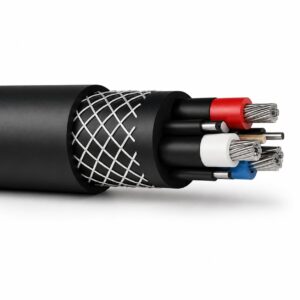
Câble minier type 241.1 1.1 kV | Gamme type 241
Une autre option de câble pour une application ou des conditions de service différentes.
Voir le produitDemandez une recommandation et un devis pour un câble.
Indiquez les fonctions requises, la longueur du câble, les contraintes mécaniques, l’environnement, les terminaisons et la quantité. Notre équipe évaluera l’aptitude à l’application avant d’établir une soumission.
- Veuillez inclure le nom du produit ou son SKU, ainsi que la longueur et la quantité de câble requises.
- Joignez une fiche technique, un dessin ou une fiche de spécifications si disponible.