










FFCT Fluoroplastic Cable 600 V 200°C
600 V fluoroplastic cable for equipment-internal wiring, with a 200°C temperature rating. Choose FFCT, stainless-braided FFCTB, overall-screened FFCT-SB or screened and protected FFCTB-SB.
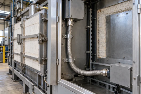
FFCT cable is a 600 V flexible fluoroplastic cable for internal wiring in equipment exposed to high temperatures. The insulation and sheath use a flexible fluoroplastic compound with a 200°C temperature rating. Applications include connections inside furnace equipment, steel-processing machinery and other heat-intensive industrial assemblies.
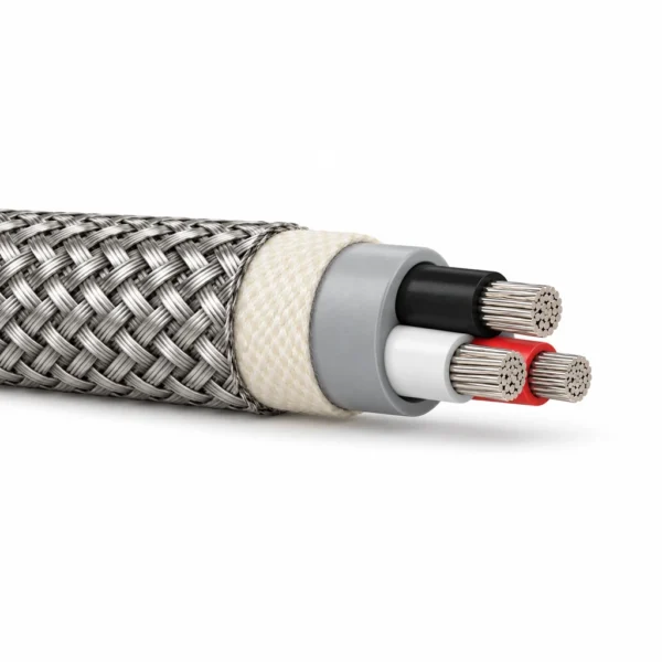
The family offers four constructions. FFCT combines fluoroplastic-insulated conductors with a fluoroplastic sheath. FFCTB adds glass tape and an external stainless-steel braid. FFCT-SB includes an overall electrical screen beneath the sheath, while FFCTB-SB combines that screen with the external glass-tape and stainless-steel protection. Select the screen and outer protection to suit the equipment connection and handling conditions.
The configuration tables cover single-core power sizes and multicore arrangements, with conductor stranding, insulation thickness, cable diameter, approximate weight and electrical data. Current ratings are stated for one cable in air at 40°C ambient. Use the table for the selected construction when checking the required conductor area, available routing space and termination size.
For a quotation, specify the FFCT model, core count, conductor area, length and equipment temperature conditions. Include the required screen termination and mechanical protection. The cable is intended for equipment-internal wiring; route it with suitable support and clearance from hot surfaces. Compare the related high-temperature wire and braided-cable options when the connection requires a different insulation or sheath system.
Explore the high-temperature cable range for related configurations.
When comparing 600 V 200°C FFCT multicore fluoroplastic cable against braided silicone multicore or single-core fluoropolymer hook-up wires, evaluate these options: SRG-K Multicore Silicone-Aramid Braided Cable, 200°C 600 V (600 V 200°C silicone-insulated multicore cable with abrasion-resistant aramid fiber outer braid); FEP Hook Up Wire 150–200°C, 300/600 V UL AWM Styles (150–200°C single-conductor FEP hook-up wire in 300 V and 600 V UL AWM styles for internal cabinet harnesses). Select fluoroplastic FFCT where chemical, solvent, and oil immersion accompany 200°C heat.
Construction
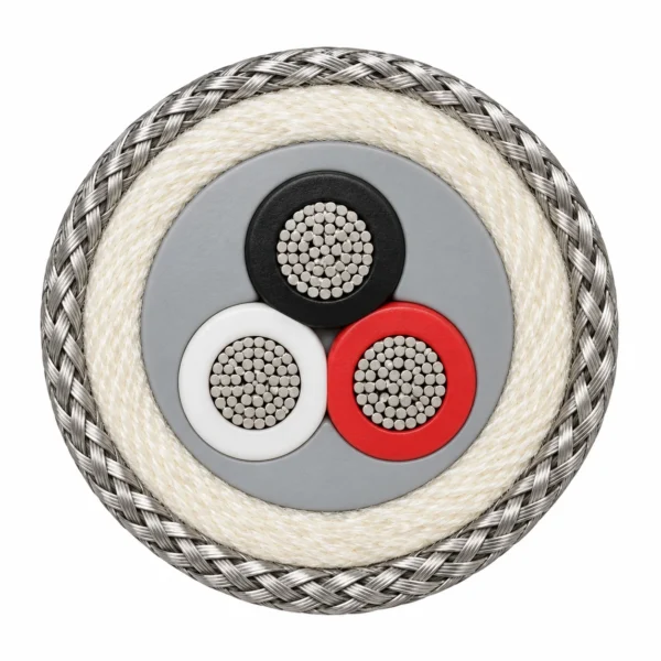
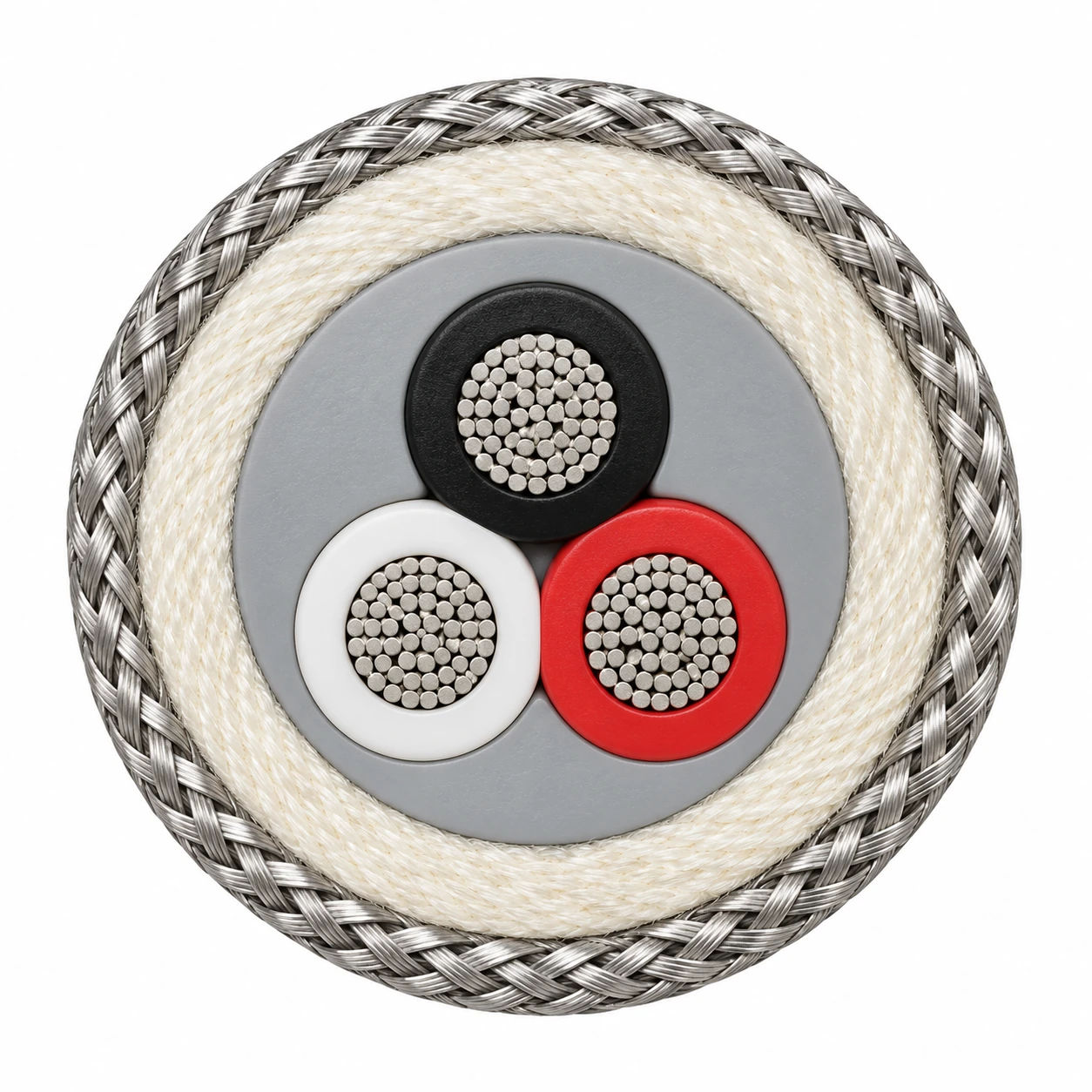
Four fluoroplastic constructions cover unscreened, overall-screened and externally protected equipment wiring. The illustration represents FFCTB 3×2 mm², with three cores in a compact triangular arrangement.
| Component | Material and construction |
|---|---|
| Conductors | Flexible stranded conductors; the complete stranding and diameter data are listed by configuration. |
| Core separator and insulation | Separator over each conductor, followed by flexible fluoroplastic insulation. |
| Core assembly | Laid-up insulated cores with binding tape; screened versions also use fillers and separating tapes. |
| FFCT / FFCTB sheath | Flexible fluoroplastic sheath around the core assembly. |
| FFCT-SB / FFCTB-SB screen | Overall braided screen beneath the fluoroplastic sheath. |
| FFCTB / FFCTB-SB outer protection | Glass tape, 1.6 mm, followed by an external stainless-steel braid, 0.8 mm. |
| Core identification | Colour and tracer identification; the representative three-core arrangement uses black, white and red. |
Applications
Specify FFCT for internal equipment connections requiring heat resistance and flexibility. Select the screened or externally protected version to match the electrical and mechanical requirements.
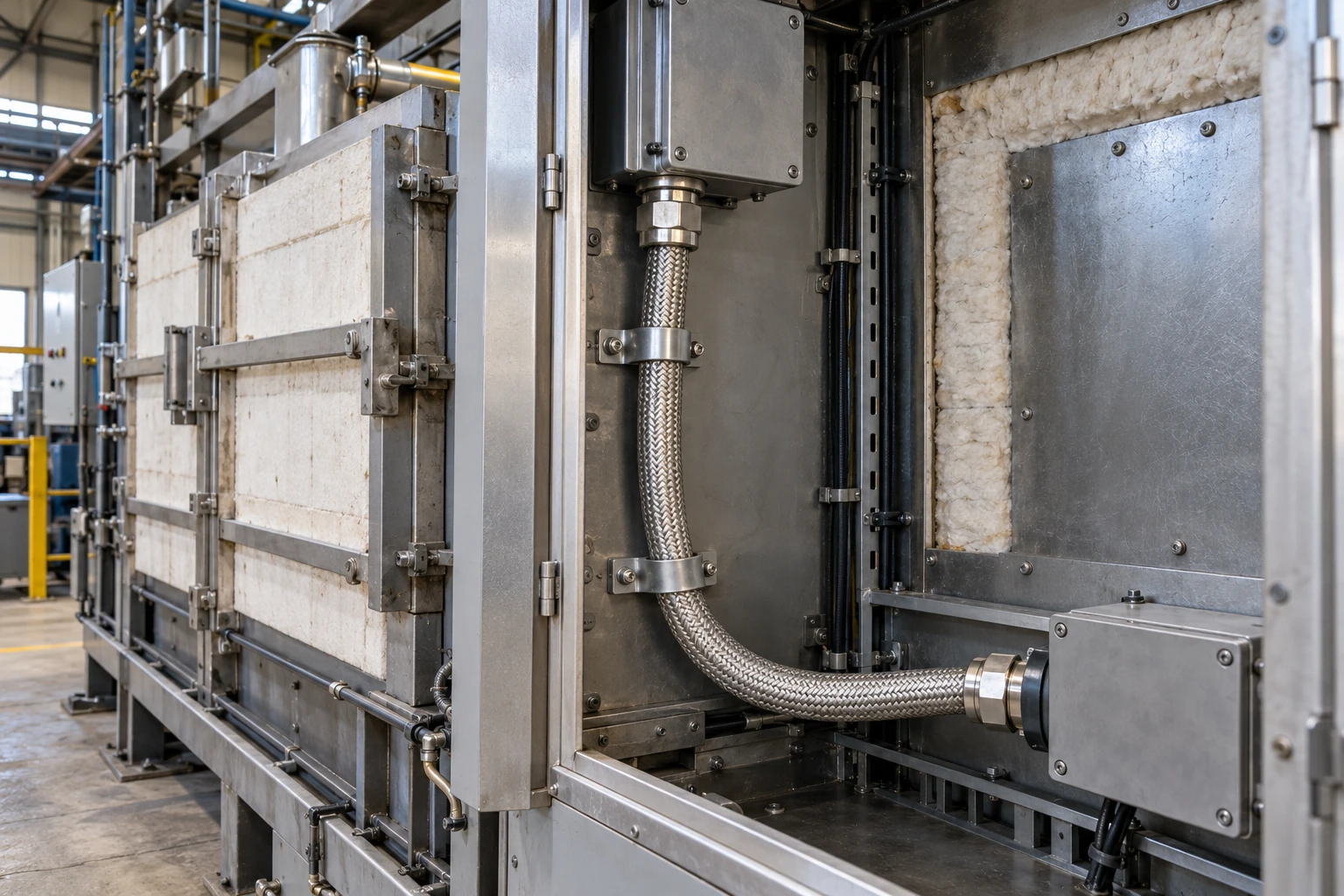
- Internal wiring in furnace and heat-processing equipment.
- Connections inside steel-processing machinery.
- Screened equipment wiring with FFCT-SB or FFCTB-SB.
- Protected internal wiring with the glass tape and stainless-steel braid of FFCTB or FFCTB-SB.
For thermal-class selection above 200°C or custom high-temperature insulation engineering, consult these technical pages: High Temperature Wire Manufacturer (overview of FEP, PTFE, PFA, silicone, and mica-glass insulation systems up to 500°C); PTFE Hook Up Wire up to 250°C, 150–1000 V UL AWM Styles (single-core PTFE hook-up wire rated up to 250°C and 150–1000 V for extreme thermal zones). Verify conductor plating (tin, silver, or nickel) against your maximum continuous operating temperature.
Specifications
| Parameter | Value |
|---|---|
| Rated voltage | AC 600 V |
| Temperature rating | 200°C |
| AC test voltage | 3000 V for 1 minute |
| Insulation and sheath | Flexible fluoroplastic compound |
| Available core counts | FFCT / FFCTB: 1, 2, 3, 4, 6, 10, 20 and 30; screened versions: 2, 3, 4, 6, 10, 20 and 30 |
| Conductor areas | Single-core FFCT / FFCTB: 100, 200 and 325 mm²; multicore configurations: 2 and 3.5 mm² as listed |
| Reference current conditions | One cable in air at 40°C ambient |
| Electrical screening | Overall braid on FFCT-SB and FFCTB-SB |
| External mechanical protection | Glass tape and stainless-steel braid on FFCTB and FFCTB-SB |
| Installation | Equipment-internal wiring |
| Model and configuration (mm²) | Stranding (No./mm) | Conductor OD (mm) | Insulation (mm) | Sheath (mm) | Approx. OD (mm) | Approx. weight (kg/km) | Max. resistance at 20°C (Ω/km) | Min. insulation resistance at 20°C (MΩ·km) | Current at 40°C ambient (A) |
|---|---|---|---|---|---|---|---|---|---|
| FFCT 1×100 | 19/37/0.45 | 15.2 | 1.0 | 2.4 | 22 | 1230 | 0.193 | 600 | 560 |
| FFCT 1×200 | 37/34/0.45 | 21.2 | 1.2 | 2.8 | 29 | 2270 | 0.0993 | 500 | 855 |
| FFCT 1×325 | 37/55/0.45 | 27.0 | 1.3 | 3.2 | 36 | 3660 | 0.0614 | 500 | 1150 |
| FFCT 2×2 | 37/0.26 | 1.8 | 0.4 | 1.7 | 9.5 | 140 | 10.2 | 1500 | 37 |
| FFCT 2×3.5 | 45/0.32 | 2.5 | 0.4 | 1.8 | 11.5 | 205 | 5.54 | 1500 | 54 |
| FFCT 3×2 | 37/0.26 | 1.8 | 0.4 | 1.7 | 10.0 | 165 | 10.2 | 1500 | 32 |
| FFCT 3×3.5 | 45/0.32 | 2.5 | 0.4 | 1.8 | 12.0 | 245 | 5.54 | 1500 | 46 |
| FFCT 4×2 | 37/0.26 | 1.8 | 0.4 | 1.8 | 11.0 | 200 | 10.2 | 1500 | 29 |
| FFCT 4×3.5 | 45/0.32 | 2.5 | 0.4 | 1.9 | 13.0 | 300 | 5.54 | 1500 | 42 |
| FFCT 6×2 | 37/0.26 | 1.8 | 0.4 | 1.9 | 13.0 | 290 | 10.2 | 1500 | 25 |
| FFCT 10×2 | 37/0.26 | 1.8 | 0.4 | 2.1 | 16.5 | 480 | 10.2 | 1500 | 20 |
| FFCT 20×2 | 37/0.26 | 1.8 | 0.4 | 2.4 | 22 | 825 | 10.2 | 1500 | 16 |
| FFCT 30×2 | 37/0.26 | 1.8 | 0.4 | 2.6 | 25 | 1190 | 10.2 | 1500 | 13 |
| Model and configuration (mm²) | Stranding (No./mm) | Conductor OD (mm) | Insulation (mm) | Sheath (mm) | Glass tape (mm) | Stainless braid (mm) | Approx. OD (mm) | Approx. weight (kg/km) | Max. resistance at 20°C (Ω/km) | Min. insulation resistance at 20°C (MΩ·km) | Current at 40°C ambient (A) |
|---|---|---|---|---|---|---|---|---|---|---|---|
| FFCTB 1×100 | 19/37/0.45 | 15.2 | 1.0 | 2.4 | 1.6 | 0.8 | 27 | 1560 | 0.193 | 600 | 500 |
| FFCTB 1×200 | 37/34/0.45 | 21.2 | 1.2 | 2.8 | 1.6 | 0.8 | 34 | 2710 | 0.0993 | 500 | 740 |
| FFCTB 1×325 | 37/55/0.45 | 27.0 | 1.3 | 3.2 | 1.6 | 0.8 | 40 | 4180 | 0.0614 | 1500 | 980 |
| FFCTB 2×2 | 37/0.26 | 1.8 | 0.4 | 1.7 | 1.6 | 0.8 | 14.5 | 310 | 10.2 | 1500 | 36 |
| FFCTB 2×3.5 | 45/0.32 | 2.5 | 0.4 | 1.8 | 1.6 | 0.8 | 16.0 | 395 | 5.54 | 1500 | 52 |
| FFCTB 3×2 | 37/0.26 | 1.8 | 0.4 | 1.7 | 1.6 | 0.8 | 15.0 | 340 | 10.2 | 1500 | 31 |
| FFCTB 3×3.5 | 45/0.32 | 2.5 | 0.4 | 1.8 | 1.6 | 0.8 | 16.5 | 445 | 5.54 | 1500 | 46 |
| FFCTB 4×2 | 37/0.26 | 1.8 | 0.4 | 1.8 | 1.6 | 0.8 | 16.0 | 390 | 10.2 | 1500 | 28 |
| FFCTB 4×3.5 | 45/0.32 | 2.5 | 0.4 | 1.9 | 1.6 | 0.8 | 18.0 | 515 | 5.54 | 1500 | 43 |
| FFCTB 6×2 | 37/0.26 | 1.8 | 0.4 | 1.9 | 1.6 | 0.8 | 18.0 | 505 | 10.2 | 1500 | 25 |
| FFCTB 10×2 | 37/0.26 | 1.8 | 0.4 | 2.1 | 1.6 | 0.8 | 22 | 760 | 10.2 | 1500 | 20 |
| FFCTB 20×2 | 37/0.26 | 1.8 | 0.4 | 2.4 | 1.6 | 0.8 | 27 | 1190 | 10.2 | 1500 | 15 |
| FFCTB 30×2 | 37/0.26 | 1.8 | 0.4 | 2.6 | 1.6 | 0.8 | 31 | 1610 | 10.2 | 1500 | 13 |
| Model and configuration (mm²) | Stranding (No./mm) | Conductor OD (mm) | Insulation (mm) | Screen layer (mm) | Sheath (mm) | Approx. OD (mm) | Approx. weight (kg/km) | Max. resistance at 20°C (Ω/km) | Min. insulation resistance at 20°C (MΩ·km) | Current at 40°C ambient (A) |
|---|---|---|---|---|---|---|---|---|---|---|
| FFCT-SB 2×2 | 37/0.26 | 1.8 | 0.4 | 0.3 | 1.8 | 11.0 | 175 | 10.2 | 1500 | 37 |
| FFCT-SB 2×3.5 | 45/0.32 | 2.5 | 0.4 | 0.3 | 1.9 | 12.5 | 245 | 5.54 | 1500 | 54 |
| FFCT-SB 3×2 | 37/0.26 | 1.8 | 0.4 | 0.3 | 1.8 | 11.5 | 205 | 10.2 | 1500 | 32 |
| FFCT-SB 3×3.5 | 45/0.32 | 2.5 | 0.4 | 0.3 | 1.9 | 13.0 | 290 | 5.54 | 1500 | 46 |
| FFCT-SB 4×2 | 37/0.26 | 1.8 | 0.4 | 0.3 | 1.8 | 12.0 | 240 | 10.2 | 1500 | 29 |
| FFCT-SB 4×3.5 | 45/0.32 | 2.5 | 0.4 | 0.3 | 2.0 | 14.0 | 355 | 5.54 | 1500 | 42 |
| FFCT-SB 6×2 | 37/0.26 | 1.8 | 0.4 | 0.3 | 2.0 | 14.0 | 340 | 10.2 | 1500 | 25 |
| FFCT-SB 10×2 | 37/0.26 | 1.8 | 0.4 | 0.3 | 2.2 | 17.5 | 540 | 10.2 | 1500 | 20 |
| FFCT-SB 20×2 | 37/0.26 | 1.8 | 0.4 | 0.3 | 2.5 | 23 | 935 | 10.2 | 1500 | 16 |
| FFCT-SB 30×2 | 37/0.26 | 1.8 | 0.4 | 0.3 | 2.7 | 27 | 1310 | 10.2 | 1500 | 13 |
| Model and configuration (mm²) | Stranding (No./mm) | Conductor OD (mm) | Insulation (mm) | Screen layer (mm) | Sheath (mm) | Glass tape (mm) | Stainless braid (mm) | Approx. OD (mm) | Approx. weight (kg/km) | Max. resistance at 20°C (Ω/km) | Min. insulation resistance at 20°C (MΩ·km) | Current at 40°C ambient (A) |
|---|---|---|---|---|---|---|---|---|---|---|---|---|
| FFCTB-SB 2×2 | 37/0.26 | 1.8 | 0.4 | 0.3 | 1.8 | 1.6 | 0.8 | 15.5 | 360 | 10.2 | 1500 | 36 |
| FFCTB-SB 3×2 | 37/0.26 | 1.8 | 0.4 | 0.3 | 1.8 | 1.6 | 0.8 | 16.0 | 390 | 10.2 | 1500 | 31 |
| FFCTB-SB 4×2 | 37/0.26 | 1.8 | 0.4 | 0.3 | 1.8 | 1.6 | 0.8 | 17.0 | 440 | 10.2 | 1500 | 28 |
| FFCTB-SB 6×2 | 37/0.26 | 1.8 | 0.4 | 0.3 | 2.0 | 1.6 | 0.8 | 19.0 | 570 | 10.2 | 1500 | 25 |
| FFCTB-SB 10×2 | 37/0.26 | 1.8 | 0.4 | 0.3 | 2.2 | 1.6 | 0.8 | 23 | 815 | 10.2 | 1500 | 20 |
| FFCTB-SB 20×2 | 37/0.26 | 1.8 | 0.4 | 0.3 | 2.5 | 1.6 | 0.8 | 28 | 1280 | 10.2 | 1500 | 15 |
| FFCTB-SB 30×2 | 37/0.26 | 1.8 | 0.4 | 0.3 | 2.7 | 1.6 | 0.8 | 31 | 1700 | 10.2 | 1500 | 13 |
Current ratings apply to the stated single-cable, in-air installation at 40°C ambient. Account for the actual enclosure temperature and grouping when selecting conductor size.
Dimensions and weights are nominal selection data. Specify the complete model and configuration when requesting a quotation.
The 200°C value is the cable temperature rating; assess adjacent equipment surfaces and routing conditions separately.
Standards
| Standard or specification | Application |
|---|---|
| FFCT family construction | Design-specific fluoroplastic cable construction for equipment-internal wiring. |
| AC dielectric test | 3000 V for 1 minute. |
| VW-1 | Flame-test classification used in the FFCT family design specification. |
Related cable options
Compare these cable options by service combination, movement, load, voltage and transmission requirement.
SRG-K Multicore Silicone-Aramid Braided Cable, 200°C 600 V
A related cable option for a different application or duty profile.
View product
FEP Hook Up Wire 150–200°C, 300/600 V UL AWM Styles
A related cable option for a different application or duty profile.
View product
PTFE Hook Up Wire up to 250°C, 150–1000 V UL AWM Styles
A related cable option for a different application or duty profile.
View productRequest a cable recommendation and quotation
Send the required services, cable length, mechanical duty, environment, termination and quantity. Our team will review the application before quoting.
- Include the product name or SKU plus the required cable length and quantity.
- Attach a specification, drawing or data sheet when available.