











Fire-Resistant PH180 & ATEX Marine Ethernet Cable
Specialist safety-critical marine Ethernet S/FTP data cables in Cat5e, Cat6, Cat6A and Cat7: PH180 functional-integrity cables tested to IEC 60331-23 and EN 50200 for ≥ 180 minutes of continuous data transfer in fire, and ATEX gas-blocked cables built to IEC 60079-14 Annex E for runs between Zone 1/Zone 2 explosive atmospheres and safe areas.
Modern commercial ships, LNG carriers, cruise liners and offshore platforms rely on high-speed IP backbones for safety-critical automation, emergency CCTV, public address / general alarm (PAGA), dynamic positioning and cargo-containment monitoring. Standard IEC 60332-3-22 marine LAN cables stop propagating flame in a fire, but their foamed polyethylene dielectric melts above 110 °C, causing immediate loss of Ethernet link continuity.
Our PH180 Fire-Resistant Marine Ethernet series (`02YS(FE)C(FE)H 4×2×0.6/1.67-100 PIMF`) incorporates dual fire-resistant `(FE)` mineral/mica barrier layers—one over the foamed-PE insulated conductors and a second over the overall tinned copper wire braid—enabling continuous high-speed data transmission during fire for at least 180 minutes (PH180) in accordance with IEC 60331-23, EN 50200 and EN 50289-4-16. It is available across Cat5e, Cat6, Cat6A and Cat7 from AWG 22/1 to AWG 26/7.
For LNG tankers, chemical carriers and offshore units where Ethernet links pass between hazardous explosive zones (ATEX Zone 1 and Zone 2) and non-hazardous spaces, the ATEX Gas-Blocked Marine Ethernet series (`02YSFCH 4×2×0.6/1.43-100 PIMF SW`) features a stranded central element and continuous internal filling compound meeting IEC 60079-14 Annex E to prevent flammable gas migration through the cable core.
Both PH180 and ATEX families are offered with halogen-free SHF1, oil-resistant SHF2 or mud-resistant outer sheaths and optional galvanised steel wire braid (SWB) or steel wire armour (SWA). Compare the side-by-side technical parameters and AWG options below when specifying your project.
Explore the marine and offshore cable range for related configurations.
Construction
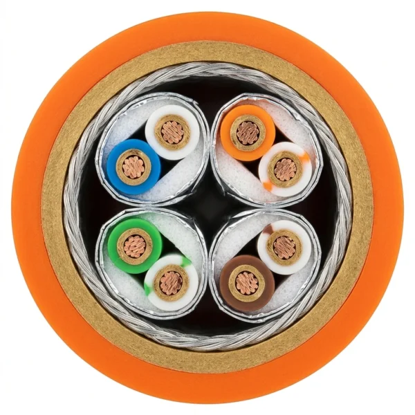
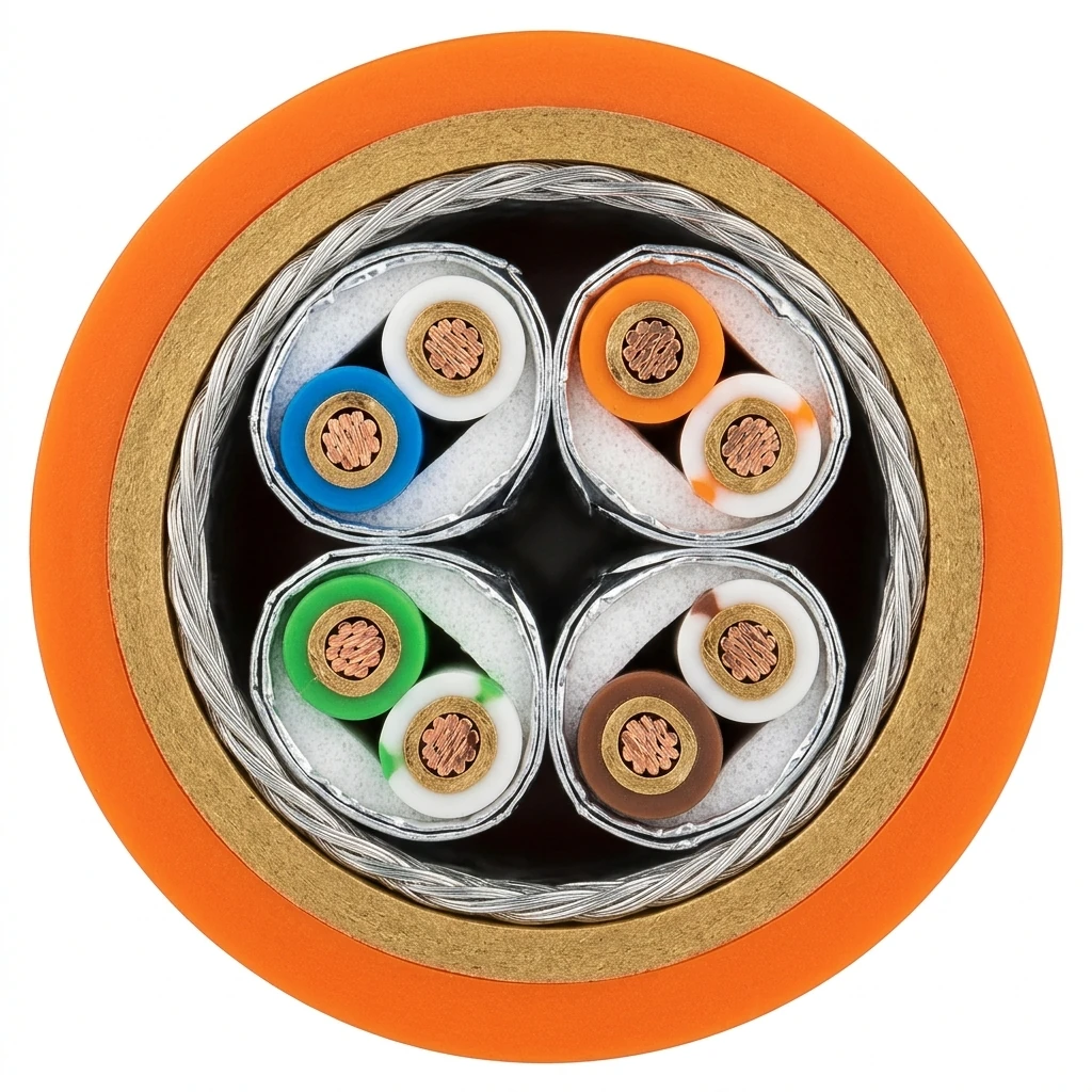
The representative cutaway illustrates the PH180 fire-resistant Cat7 S/FTP marine Ethernet cable (`02YS(FE)C(FE)H 4×2×0.6/1.67-100 PIMF`) with bare copper conductors, foamed PE insulation wrapped in a fire-resistant mica tape barrier, individual aluminium-laminated pair foils, overall tinned copper braid, outer fire-resistant barrier and orange or black FRNC SHF1/SHF2 outer sheath.
| Component | Material and construction |
|---|---|
| Conductor | Solid or stranded bare copper wire: AWG 22/1 up to AWG 26/7 on PH180 fire-resistant builds; AWG 22/1, AWG 23/1 or AWG 24/1 solid bare copper on ATEX gas-blocked builds. |
| Core insulation & primary barrier | Foamed polyethylene (PE) dielectric (1.67 mm core Ø with fire-resistant mica/mineral tape layer on PH180 builds; 1.43 mm core Ø laid around a stranded central wire on ATEX builds). |
| Individual pair shield (PIMF) | Aluminium-laminated foil tape wrapped around each of the 4 twisted pairs (100% pair coverage) for Cat5e, Cat6, Cat6A and Cat7 NEXT isolation. |
| Internal gas-blocking or fire barrier | ATEX series (`02YSFCH`): continuous internal filler compound sealing interstitial voids to IEC 60079-14 Annex E. PH180 series (`02YS(FE)C(FE)H`): secondary fire-resistant barrier layer combined with the overall screen. |
| Overall braid shield | Tin-plated copper wire braid over the 4 foil-screened pairs providing low transfer impedance and 360° EMC gland earthing. |
| Outer jacket & optional armour | Halogen-free FRNC jacket in SHF1, oil-resistant SHF2 or mud-resistant grade (orange OG or black BK/SW); optional galvanised steel wire braid (SWB) or steel wire armour (SWA) over the inner sheath. |
Applications
Choose PH180 functional-integrity LAN cables for fire-survival network backbones and ATEX gas-blocked LAN cables for hazardous-area bulkhead penetrations.
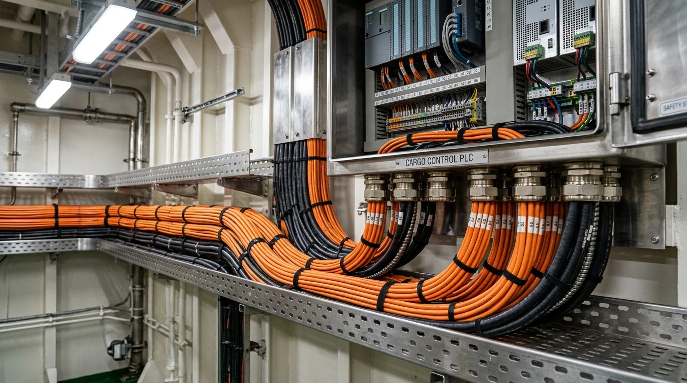
- Safe-Return-to-Port (SRtP) redundant IP backbones, emergency bridge-to-engine-room automation networks and safety PLC rings requiring ≥ 180 minutes fire survival (PH180).
- IP-based public address / general alarm (PAGA), emergency evacuation CCTV, fire-door monitoring and muster-station communication links.
- LNG carriers, LPG tankers, dual-fuel methanol/ammonia vessels and FPSOs where data cables cross between ATEX Zone 1 / Zone 2 cargo zones and safe machinery or accommodation spaces.
- Offshore drilling rigs and production platforms requiring mud-resistant and SWB/SWA steel-armoured fire-resistant or ATEX Ethernet cabling.
- High-density ATEX network cabinets and redundant switch interconnections using the 2 × 4-pair Duplex ATEX Cat6/Cat6A/Cat7 construction.
Specifications
| Parameter | Value |
|---|---|
| Transmission categories | Cat 5e (100 MHz), Cat 6 (250 MHz), Cat 6A (500 MHz) and Cat 7 (600 MHz) in 4-pair S/FTP (PIMF) construction. |
| Fire integrity rating (PH180 series) | Functional data transmission integrity ≥ 180 minutes in fire to IEC 60331-23, EN 50200 (PH180) and EN 50289-4-16. |
| Hazardous area compliance (ATEX series) | Gas-tight internal filler construction to IEC 60079-14 Annex E for transitions between ATEX Zone 1 and Zone 2 explosive atmospheres. |
| Characteristic impedance and delay | 100 ± 15 Ω (1–100 MHz); propagation delay ≤ 5.3 ns/m (PH180) and ≤ 5.13 ns/m (ATEX); insulation resistance ≥ 500 MΩ·km; test voltage 700 V AC. |
| Max. DC loop resistance | ≤ 150 Ω/km on PH180 fire-resistant series; ≤ 140 Ω/km on ATEX gas-blocked and Duplex ATEX series. |
| Sheath and armour options | Halogen-free FRNC in SHF1, oil-resistant SHF2 or mud-resistant compound; unarmoured or armoured with galvanised steel SWB or SWA. |
| Flame, smoke and gas emission | IEC 60332-1-2 single flame, IEC 60332-3-22 Cat. A bunched fire test, IEC 60754-1/-2 halogen-free and IEC 61034-1/-2 low smoke density. |
| Temperature and bending radius | Operation: −25 °C to +80 °C (−40 °C to +80 °C on Duplex); Installation: −10 °C to +80 °C; Min. bend radius: 10 × OD operation / 7.5 × OD installation. |
| Series & configuration | Conductor range | Core & internal barrier design | Screening & armour | Outer jacket options | Categories & primary compliance |
|---|---|---|---|---|---|
| PH180 Fire-Resistant Marine Ethernet S/FTP (Unarmoured) | Solid or stranded bare copper (AWG 22/1 to AWG 26/7) | Foamed PE + fire-resistant mica/mineral barrier layer around cores | Individual pair Al-laminated foil + tinned copper braid + fire-resistant barrier | Halogen-free FRNC SHF1, SHF2 or mud-resistant (Orange OG or Black BK) | Cat5e, Cat6, Cat6A, Cat7; IEC 60331-23 & EN 50200 (≥ 180 min fire integrity) |
| PH180 Fire-Resistant Marine Ethernet S/FTP (SWB / SWA Armoured) | Solid or stranded bare copper (AWG 22/1 to AWG 26/7) | Foamed PE + fire-resistant mica/mineral barrier layer around cores | Individual pair Al-laminated foil + tinned copper braid + galvanised steel SWB or SWA | Halogen-free FRNC SHF1, SHF2 or mud-resistant (Orange OG or Black BK) | Cat5e, Cat6, Cat6A, Cat7; heavy mechanical + 180 min fire protection |
| ATEX Gas-Blocked Marine Ethernet S/FTP (Unarmoured) | Solid bare copper (AWG 22/1, AWG 23/1, AWG 24/1) | Foamed PE over central stranded element + internal gas-blocking filler compound | Individual pair Al-laminated foil + overall tinned copper wire braid | Halogen-free FRNC SHF1, SHF2 or mud-resistant (Black SW) | Cat5e, Cat6, Cat6A, Cat7; IEC 60079-14 Annex E (ATEX Zone 1 & Zone 2) |
| ATEX Gas-Blocked Marine Ethernet S/FTP (SWB / SWA Armoured) | Solid bare copper (AWG 22/1, AWG 23/1, AWG 24/1) | Foamed PE over central stranded element + internal gas-blocking filler compound | Individual pair Al-laminated foil + tinned copper braid + galvanised steel SWB or SWA | Halogen-free FRNC SHF1, SHF2 or mud-resistant (Black SW) | Cat5e, Cat6, Cat6A, Cat7; hazardous deck, LNG tank dome & offshore zones |
| ATEX Duplex Marine Ethernet S/FTP (2 × 4-Pair Figure-8 / Twin) | Solid bare copper (2 × 4 × 2 × AWG 22/1 to 24/1) | Foamed PE (0.6/1.43 mm) in dual 4-pair construction | Individual pair Al-laminated foil + overall tinned copper wire braid per element | Halogen-free FRNC SHF1 / SHF2 (Black SW) | Cat6, Cat6A, Cat7; IEC 60079-14 Annex E dual-link cabinet & bulkhead wiring |
| Parameter | PH180 Fire-Resistant S/FTP | ATEX Gas-Blocked S/FTP | Duplex ATEX 2 × 4-Pair S/FTP |
|---|---|---|---|
| DIN / VDE type designation | 02YS(FE)C(FE)H 4×2×0.6/1.67-100 PIMF (OG / BK) | 02YSFCH 4×2×0.6/1.43-100 PIMF SW | 02YSCH 2×4×2×0.6/1.43-100 PIMF SW |
| Reference catalog order no. | L45467-J416-C626 (Orange) / L45467-J416-C616 (Black) | L45467-J416-C796 (Black) | L45467-J816-C126 (Black) |
| Supported transmission categories | Cat 7, Cat 6A, Cat 6, Cat 5e | Cat 7, Cat 6A, Cat 6, Cat 5e | Cat 7, Cat 6A, Cat 6 |
| Available conductor sizes | AWG 22/1 up to AWG 26/7 (solid or stranded) | AWG 22/1, AWG 23/1, AWG 24/1 (solid) | AWG 22/1 (0.6 mm) and other AWG options |
| Reference conductor / core insulation Ø | 0.6 mm conductor / 1.67 mm over fire-barrier core | 0.6 mm conductor / 1.43 mm over foamed PE core | 2 × (4 × 2 × 0.6 / 1.43 mm) dual 4-pair |
| Special internal protection mechanism | Dual fire-resistant (FE) mica/mineral barrier layers (core + over braid) | Stranded central element + continuous internal gas-blocking filler compound | Dual 4-pair S/FTP in common sheath meeting IEC 60079-14 Annex E |
| Fire integrity / ATEX standard | IEC 60331-23 and EN 50200 (PH180 functional integrity ≥ 180 min) | IEC 60079-14 Annex E (ATEX Zone 1 and Zone 2 bulkhead transits) | IEC 60079-14 Annex E (ATEX network cabinet and switch interconnections) |
| Shipboard design standards | IEC 60092-350, -360, -376, -379; EN 50289-4-16 | IEC 60092-350, -360, -376, -379; IEC 60079-14 Annex E | IEC 60092-350, -360, -376, -379; IEC 60079-14 Annex E |
| Flame, smoke & gas standards | IEC 60332-1-2, IEC 60332-3-22, IEC 61034-1/-2, IEC 60754-1/-2 | IEC 60332-1-2, IEC 60332-3-22, IEC 61034-2, IEC 60754-1/-2 | IEC 60332-1-2, IEC 60332-3-22, IEC 61034-2, IEC 60754-1/-2 |
| Characteristic impedance | 100 ± 15 Ω (1–100 MHz) | 100 ± 15 Ω (1–100 MHz) | 100 ± 5 Ω at 100 MHz |
| Max. DC loop resistance | ≤ 150 Ω/km | ≤ 140 Ω/km | ≤ 140 Ω/km |
| Signal propagation delay (transit time) | ≤ 5.3 ns/m | ≤ 5.13 ns/m | ≤ 5.13 ns/m (standard foamed PE 0.6/1.43 core) |
| Min. insulation resistance | ≥ 500 MΩ·km | ≥ 500 MΩ·km | ≥ 500 MΩ·km (operating voltage ≤ 100 V peak) |
| Dielectric test voltage (core/core/shield) | 700 V AC | 700 V AC | 700 V AC |
| Operating / installation temperature | −25 °C to +80 °C / −10 °C to +80 °C | −25 °C to +80 °C / −10 °C to +80 °C | −40 °C to +80 °C / −30 °C to +80 °C |
| Min. bending radius (operation / install) | 10 × D / 7.5 × D | 10 × D / 7.5 × D | 8 × D / 4 × D |
| Available outer sheath & armour options | SHF1, SHF2, mud-resistant; optional SWB or SWA galvanised steel | SHF1, SHF2, mud-resistant; optional SWB or SWA galvanised steel | FRNC SHF1 / SHF2 |
| AWG designation | Conductor geometry (area) | Nominal conductor Ø (mm) | Nominal insulated core Ø (mm) | PH180 series availability | ATEX series availability | Sheath & armour options |
|---|---|---|---|---|---|---|
| AWG 22/1 (Solid) | 1 × 0.64 mm (0.324 mm²) | 0.64 | 1.67 (PH180) / 1.43 (ATEX) | Yes (Cat7 / Cat6A / Cat6) | Yes (Cat7 / Cat6A / Cat6) | SHF1, SHF2, MUD; Unarmoured, SWB or SWA |
| AWG 22/7 (Stranded) | 7 × 0.254 mm (0.355 mm²) | 0.76 | 1.67 (PH180) | Yes (Flexible PH180) | On request | SHF1, SHF2, MUD; Unarmoured, SWB or SWA |
| AWG 23/1 (Solid) | 1 × 0.574 mm (0.259 mm²) | 0.57 | 1.67 (PH180) / 1.43 (ATEX) | Yes (Cat7 / Cat6A / Cat6) | Yes (Cat7 / Cat6A / Cat6) | SHF1, SHF2, MUD; Unarmoured, SWB or SWA |
| AWG 24/1 (Solid) | 1 × 0.511 mm (0.205 mm²) | 0.51 | 1.67 (PH180) / 1.43 (ATEX) | Yes (Cat6 / Cat5e) | Yes (Cat6 / Cat5e) | SHF1, SHF2, MUD; Unarmoured, SWB or SWA |
| AWG 24/7 (Stranded) | 7 × 0.203 mm (0.227 mm²) | 0.61 | 1.67 (PH180) | Yes (Flexible PH180) | On request | SHF1, SHF2, MUD; Unarmoured, SWB or SWA |
| AWG 26/7 (Stranded) | 7 × 0.160 mm (0.141 mm²) | 0.48 | 1.67 (PH180) | Yes (Patch / work-area PH180) | — | SHF1, SHF2, MUD; Unarmoured, SWB or SWA |
In the source catalog (pp. 4, 5, 8), maximum loop resistance is printed with the unit "mΩ/km" (≤ 150 and ≤ 140), which is a standard typographic misprint for Ω/km on AWG 22–24 copper data pairs (where single-conductor DC resistance is 55–85 Ω/km and loop resistance is 110–170 Ω/km).
Because PH180 fire-resistant cores include a mica/mineral fire barrier over the foamed PE dielectric, the nominal core diameter over insulation increases from 1.43 mm (standard/ATEX AWG 22) to 1.67 mm; ensure field-terminated RJ45 plugs and cable glands are sized for the 1.67 mm core insulation diameter.
ATEX Ethernet cables (`02YSFCH`) incorporate an extruded/filled interstitial gas-blocking compound around a central stranded element so the cable passes the IEC 60079-14 Annex E restricted-breathing / gas-transmission test when routed through Ex d / Ex e cable glands between Zone 1/2 and safe spaces.
For standard non-fire-resistant and non-ATEX shipboard Cat5e, Cat6A, Cat7 and Cat7A S/FTP LAN cables (including −65 °C Arctic and 2-pair PROFINET builds), see our general Marine Ethernet Cable page.
Standards
| Standard or specification | Application |
|---|---|
| IEC 60331-23 & EN 50200 (PH180) | Circuit integrity fire test for electric data cables and method of test for resistance to fire of unprotected small cables for emergency circuits (≥ 180 minutes functional data transmission). |
| EN 50289-4-16 | Communication cables—specifications for test methods—environmental test methods: circuit integrity under fire conditions. |
| IEC 60079-14 (Annex E) | Explosive atmospheres—electrical installations design, selection and erection (construction and gas-tightness verification for cables traversing ATEX Zone 1 and Zone 2 boundaries). |
| IEC 60092-350, -360, -376 & -379 | Shipboard electrical installations—general construction, testing, SHF1/SHF2 halogen-free sheathing and shipboard telecommunication/data cable requirements. |
| ISO/IEC 11801 & IEC 61156-5 / -6 | Category 5e, Category 6, Category 6A and Category 7 balanced pair digital communication cable transmission performance. |
| IEC 60332-1-2, IEC 60332-3-22 (Cat. A), IEC 60754-1/-2 & IEC 61034-1/-2 | Single and bunched Category A flame retardance, zero halogen acid gas and low smoke opacity. |
IEC 60331-23 circuit integrity fire test for electric data cables scope
Related cable options
Compare these cable options by service combination, movement, load, voltage and transmission requirement.

Halogen-Free Cat5e–Cat7 Marine Ethernet Cable
A related cable option for a different application or duty profile.
View product
IEC 60331 Fire-Resistant Shipboard Power Cable
A related cable option for a different application or duty profile.
View product
Halogen-Free Shipboard Marine Fieldbus Cable
A related cable option for a different application or duty profile.
View productRequest a cable recommendation and quotation
Send the required services, cable length, mechanical duty, environment, termination and quantity. Our team will review the application before quoting.
- Include the product name or SKU plus the required cable length and quantity.
- Attach a specification, drawing or data sheet when available.