








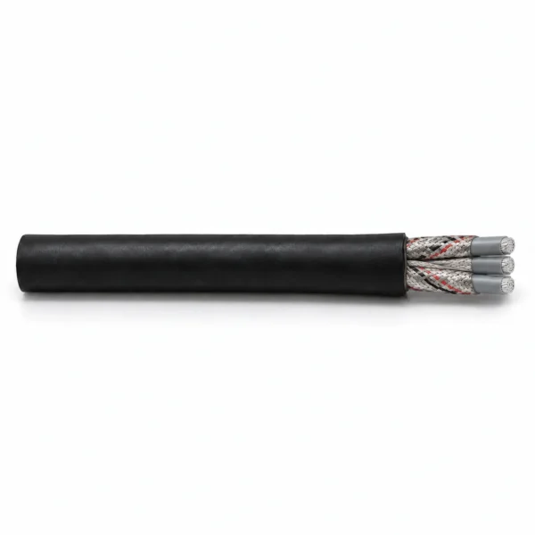
SHD-CGC FOM 5 kV Mining Power Cable with Multimode Fibres
SHD-CGC FOM 5 kV cable combines three individually screened power cores, two bare earth conductors, a central insulated ground-check conductor and a multimode optical unit. Select 6 or 12 fibres and the required jacket construction. MOQ: 50 m; lead time: 7–45 working days.
SHD-CGC FOM mining cable combines a 5 kV power circuit with multimode optical communication in one portable cable. Three individually screened phase cores supply the load, while two bare earth conductors and a separate insulated ground-check conductor provide distinct connections for the equipment grounding and monitoring circuits. The optical module occupies an interstitial position beside the power cores; the ground-check conductor remains at the centre.
Start the selection with the complete circuit arrangement. A six-fibre optical module and a twelve-fibre module give different termination requirements, and the 50/125 µm or 62.5/125 µm fibre choice must match the optical equipment. Keep the fibre count, fibre type and ground-check details on the order together with the power-conductor size. The listed 5 kV reference series spans 6 AWG to 500 kcmil, with separate grounding sizes and mechanical data for each row.
Choose the jacket and cable route as one system. The black polychloroprene construction and optional TPU jacket need to be matched to the movement, minimum temperature, pulling arrangement and termination hardware. A shared reference diameter is not a substitute for checking the final optical configuration and connector entry. For a different circuit arrangement, compare the related power-and-fibre constructions before ordering. TEBAOFLEX supplies this family from a 50 m minimum order, with a lead time of 7–45 working days. Send the complete power, earth, ground-check and fibre requirements for a construction-specific quotation.
Explore the mining and tunneling cable range for related configurations.
Construction
SHD-CGC FOM keeps the optical unit, protective-earth conductors and central ground-check core electrically and physically distinct. Each power core has its own conductor screen, EPR insulation and composite metallic/textile braid.
| Component | Material and construction |
|---|---|
| Power conductors | Three annealed, flexible stranded tinned-copper conductors; the strand and bunch counts are listed by size. |
| Conductor screen | Semiconductive layer over each power conductor. |
| Power insulation | Ethylene-propylene rubber (EPR). |
| Individual phase screen | Non-conducting bedding tape beneath a composite tinned-copper/polyamide braid, with at least 60% braid coverage. |
| Phase identification | Black, white and red polyamide identification within the three phase-screen braids. |
| Protective earth | Two bare annealed tinned-copper grounding conductors in the outer interstices; each conductor has the grounding size shown in the table. |
| Ground check | One separately insulated ground-check conductor at the centre of the assembly. |
| Optical unit | One interstitial optical element with colour-coded fibres and filled buffering tubes; 6 or 12 multimode fibres with 50/125 µm or 62.5/125 µm geometry selected for the order. |
| Assembly and binder | Power cores, two earth conductors and the optical unit are laid around the central ground-check core. A single-faced rubber-filled binder tape surrounds the assembly. |
| Outer jacket | Black extra-heavy-duty reinforced thermosetting polychloroprene jacket; TPU is a separate jacket option. |
Applications
Use the combined power-and-optical construction where a mine-equipment route needs both the electrical supply and a fibre link. Select the movement duty and end connections for the complete assembly.
- Portable mining power routes with a 5 kV supply and an optical communication requirement.
- Quarry and shaft-sinking equipment connections that require separate earth and ground-check circuits.
- Heavy industrial routes subject to abrasion, impact, oil and weather exposure, with the jacket chosen for the installation.
- Replacement enquiries where the existing power size, two-earth arrangement, central ground check and multimode fibre interface can be matched individually.
- Reel, guide and support arrangements reviewed together with the 8 × diameter minimum bend radius, cable weight and tensile-force limit. Specify reverse bending and movement conditions separately.
For route and construction selection, see the medium-voltage mining cable selection guide.
For a 5 kV central-ground-check cable without this optical arrangement, compare Type SHD-CGC mining cable. Its grounding layout and dimensions must be checked independently.
Where the optical system requires single-mode fibres, review the 5 kV-class PCBU-GC-FO construction with 24 single-mode fibres or SHD-GC-FO 35 kV cable with 12 single-mode fibres. These are different voltage or circuit constructions; fibre count alone does not establish interchangeability.
Specifications
| Parameter | Value |
|---|---|
| Cable family | SHD-CGC FOM |
| Rated voltage | 5 kV |
| Power circuit | Three individually screened phase cores |
| Earth and ground check | Two bare earth conductors plus one central insulated ground-check conductor |
| Optical selection | 6 or 12 multimode fibres; 50/125 µm or 62.5/125 µm |
| Power-conductor reference range | 6 AWG–500 kcmil |
| Insulation / jacket | EPR / black polychloroprene; TPU jacket option |
| Minimum bending radius | 8 × cable overall diameter |
| Ampacity reference temperatures | 90°C conductor / 40°C ambient |
| Minimum order quantity | 50 m |
| Lead time | 7–45 working days |
| Model and circuit configuration | Power strand count | Power bunch arrangement | Each earth size | Earth strand count | Earth bunch arrangement |
|---|---|---|---|---|---|
| SHD-CGC FOM 3 × 6 AWG + 2 × 10 AWG G + central GC + FOM | 133 | 7 × 19 | 10 AWG | 49 | 7 × 7 |
| SHD-CGC FOM 3 × 4 AWG + 2 × 8 AWG G + central GC + FOM | 259 | 7 × 37 | 8 AWG | 133 | 7 × 19 |
| SHD-CGC FOM 3 × 2 AWG + 2 × 6 AWG G + central GC + FOM | 259 | 7 × 37 | 6 AWG | 133 | 7 × 19 |
| SHD-CGC FOM 3 × 1 AWG + 2 × 5 AWG G + central GC + FOM | 259 | 7 × 37 | 5 AWG | 133 | 7 × 19 |
| SHD-CGC FOM 3 × 1/0 AWG + 2 × 4 AWG G + central GC + FOM | 266 | 19 × 14 | 4 AWG | 259 | 7 × 37 |
| SHD-CGC FOM 3 × 2/0 AWG + 2 × 3 AWG G + central GC + FOM | 342 | 19 × 18 | 3 AWG | 259 | 7 × 37 |
| SHD-CGC FOM 3 × 3/0 AWG + 2 × 2 AWG G + central GC + FOM | 418 | 19 × 22 | 2 AWG | 259 | 7 × 37 |
| SHD-CGC FOM 3 × 4/0 AWG + 2 × 1 AWG G + central GC + FOM | 532 | 19 × 28 | 1 AWG | 259 | 7 × 37 |
| SHD-CGC FOM 3 × 250 kcmil + 2 × 1/0 AWG G + central GC + FOM | 627 | 19 × 33 | 1/0 AWG | 266 | 19 × 14 |
| SHD-CGC FOM 3 × 350 kcmil + 2 × 2/0 AWG G + central GC + FOM | 888 | 37 × 24 | 2/0 AWG | 342 | 19 × 18 |
| SHD-CGC FOM 3 × 500 kcmil + 2 × 4/0 AWG G + central GC + FOM | 1221 | 37 × 33 | 4/0 AWG | 532 | 19 × 28 |
| Model and circuit configuration | EPR insulation (in.) | Jacket (in.) | Approx. OD (in.) | Approx. mass (lb/1000 ft) | Approx. mass (kg/km) | Maximum tensile force (N) |
|---|---|---|---|---|---|---|
| SHD-CGC FOM 3 × 6 AWG + 2 × 10 AWG G + central GC + FOM | 0.110 | 0.185 | 1.51 | 1543 | 2296 | 600 |
| SHD-CGC FOM 3 × 4 AWG + 2 × 8 AWG G + central GC + FOM | 0.110 | 0.185 | 1.60 | 1849 | 2752 | 950 |
| SHD-CGC FOM 3 × 2 AWG + 2 × 6 AWG G + central GC + FOM | 0.110 | 0.205 | 1.79 | 2358 | 3509 | 1500 |
| SHD-CGC FOM 3 × 1 AWG + 2 × 5 AWG G + central GC + FOM | 0.110 | 0.205 | 1.88 | 2430 | 3618 | 1900 |
| SHD-CGC FOM 3 × 1/0 AWG + 2 × 4 AWG G + central GC + FOM | 0.110 | 0.220 | 2.08 | 3056 | 4549 | 2400 |
| SHD-CGC FOM 3 × 2/0 AWG + 2 × 3 AWG G + central GC + FOM | 0.110 | 0.220 | 2.12 | 3689 | 5490 | 3000 |
| SHD-CGC FOM 3 × 3/0 AWG + 2 × 2 AWG G + central GC + FOM | 0.110 | 0.235 | 2.26 | 4320 | 6443 | 3800 |
| SHD-CGC FOM 3 × 4/0 AWG + 2 × 1 AWG G + central GC + FOM | 0.110 | 0.235 | 2.51 | 4699 | 6994 | 4800 |
| SHD-CGC FOM 3 × 250 kcmil + 2 × 1/0 AWG G + central GC + FOM | 0.120 | 0.250 | 2.57 | 5825 | 8670 | 5800 |
| SHD-CGC FOM 3 × 350 kcmil + 2 × 2/0 AWG G + central GC + FOM | 0.120 | 0.265 | 2.83 | 7414 | 11035 | 7900 |
| SHD-CGC FOM 3 × 500 kcmil + 2 × 4/0 AWG G + central GC + FOM | 0.120 | 0.280 | 3.18 | 9602 | 14292 | 11400 |
| Model and power size | Power resistance at 25°C (Ω/1000 ft) | Earth resistance at 25°C (Ω/1000 ft) | Inductance (mH/1000 ft) | Operating capacitance (µF/1000 ft) | Reference ampacity (A) |
|---|---|---|---|---|---|
| SHD-CGC FOM 3 × 6 AWG | 0.436 | 1.109 | 0.132 | 0.08 | 93 |
| SHD-CGC FOM 3 × 4 AWG | 0.274 | 0.697 | 0.119 | 0.09 | 122 |
| SHD-CGC FOM 3 × 2 AWG | 0.172 | 0.436 | 0.112 | 0.10 | 159 |
| SHD-CGC FOM 3 × 1 AWG | 0.137 | 0.349 | 0.108 | 0.11 | 184 |
| SHD-CGC FOM 3 × 1/0 AWG | 0.109 | 0.274 | 0.105 | 0.12 | 211 |
| SHD-CGC FOM 3 × 2/0 AWG | 0.0868 | 0.227 | 0.099 | 0.14 | 243 |
| SHD-CGC FOM 3 × 3/0 AWG | 0.0688 | 0.172 | 0.098 | 0.14 | 279 |
| SHD-CGC FOM 3 × 4/0 AWG | 0.0546 | 0.137 | 0.094 | 0.16 | 321 |
| SHD-CGC FOM 3 × 250 kcmil | 0.0466 | 0.109 | 0.089 | 0.18 | 355 |
| SHD-CGC FOM 3 × 350 kcmil | 0.0333 | 0.0868 | 0.085 | 0.21 | 435 |
| SHD-CGC FOM 3 × 500 kcmil | 0.0233 | 0.0546 | 0.082 | 0.24 | 536 |
| Optical arrangement | Fibre count | Core / cladding options | Ordering focus |
|---|---|---|---|
| SHD-CGC FOM 1 × 6 | 6 | 50/125 µm or 62.5/125 µm | Specify fibre geometry, connector interface and final cable dimensions. |
| SHD-CGC FOM 2 × 6 | 12 | 50/125 µm or 62.5/125 µm | Specify both six-fibre groups, connector interface and final cable dimensions. |
G means each of the two protective-earth conductors. GC means the separate central insulated ground-check conductor. Specify its conductor size and termination alongside the optical unit on the quotation and cable drawing.
The dimensional series is a nominal family reference. Select the exact 6- or 12-fibre unit, fibre geometry and jacket material before confirming the outside diameter, mass, connector entry and drum capacity.
The two mass columns retain their independently stated reference values. Use the quoted mass for drum, handling and support calculations; do not recalculate one column to replace the other.
Resistance is stated at 25°C, not 20°C. Inductance and capacitance use 1000 ft length units; 1 kcmil and the historical designation MCM represent the same conductor-area unit.
Reference ampacity uses continuous operation at 90°C conductor temperature and 40°C ambient. Apply installation and thermal corrections, including any cable remaining on a reel.
Calculate bending clearance from the final cable diameter. Evaluate the stated tensile-force limit together with the route, acceleration, guides and terminations; it does not define an unrestricted unsupported shaft length.
Specify minimum ambient temperature and whether the cable is moving, installed or being handled. Tie the agreed low-temperature performance to the selected polychloroprene or TPU jacket construction.
Select the fibre interface, link length and optical performance requirements together. A fibre core/cladding size alone does not define an OM grade, bandwidth, attenuation limit or connector system.
Standards
| Standard or specification | Application |
|---|---|
| ICEA S-75-381 / NEMA WC-58 | Portable mining cable construction reference for the listed 5 kV family. |
| ASTM B172 | Flexible rope-lay tinned-copper conductor construction reference. |
| ICEA S-75-381, Section 3.14 | Semiconductive conductor-screen reference. |
| ICEA S-75-381, Table 3-25 | Grounding-conductor construction reference. |
Official standards and approval references
The current NEMA/ICEA publication uses WC 23058 in place of the historical WC 58 designation. State the required edition with the voltage, conductor arrangement, jacket and optical configuration in the order specification.
- ANSI/NEMA WC 23058 / ICEA S-75-381 — Current portable and power-feeder cable standard for mines and similar applications.
- ASTM B172 — Rope-lay stranded copper conductors — Official conductor-standard record covering rope-lay conductors with bunch-stranded members, including tin-coated copper wire.
Certifications and document support
Review our company certificates and document scopes when identifying the documentation required for the quoted construction.
Provide the destination mine, approval body, required cable marking and complete power/earth/ground-check/fibre construction for document review. Where an order requires MSHA identification, match the approval number and permitted marking to the selected cable type, voltage and size. Optical performance and termination records should identify the ordered fibre unit.
Related cable options
Compare these cable options by service combination, movement, load, voltage and transmission requirement.
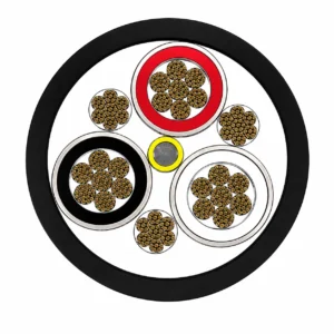
Type SHD-CGC 5 kV Shielded Portable Mining Power Cable
A related cable option for a different application or duty profile.
View product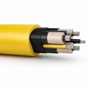
PCBU-GC-FO 5 kV Mining Power Cable with 24 Single-Mode Fibres Alternative — TEBAOFLEX
A related cable option for a different application or duty profile.
View product
SHD-GC-FO 35 kV Mining Cable with 12 Single-Mode Fibres
A related cable option for a different application or duty profile.
View productRequest a cable recommendation and quotation
Send the required services, cable length, mechanical duty, environment, termination and quantity. Our team will review the application before quoting.
- Include the product name or SKU plus the required cable length and quantity.
- Attach a specification, drawing or data sheet when available.