

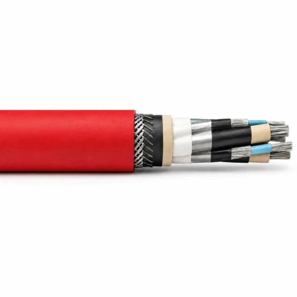
Câble à chaîne pour haveuse NTSKCGECWOEU 1.8/3–3.6/6 kV
Câble à chaîne moyenne tension pour haveuse, avec conducteurs concentriques doubles de commande/PE et protection en fils d’acier/cuivre à câblage serré.
NTSKCGECWOEU est un câble à chaîne de coupe du charbon à moyenne tension pour les équipements miniers mobiles souterrains, les machines de coupe du charbon, les chaînes de protection du câble et les gestionnaires de câbles. La fiche technique VDE fournie spécifie des conducteurs en cuivre étamé finement échoués, une isolation EPR 3GI3, un contrôle semi-conducteur à froid, une double commande concentrique et des éléments de fil PE, une gaine interne GM1B, une protection en acier et en cuivre à la couche fermée et une gaine extérieure en élastomère synthétique 5GM5 rouge. Les tableaux techniques couvrent les systèmes 1.8/3 kV et 3.6/6 kV, avec des dispositions à trois commandes et six commandes et des configurations de conducteurs de 25 mm² à 240 mm². La source énumère le fonctionnement du conducteur 90 °C, la température du court-circuit 250 °C, le service fixe de −40 °C à +90 °C et le service entièrement flexible de −20 °C à +90 °C. La géométrie de la chaîne, les cycles de mouvement, la trajectoire de traction, le rayon de flexion, les fonctions de base, la notation UEL et le matériel de terminaison doivent être vérifiés par rapport au dessin de la machine. Utiliser le tableau des dimensions ainsi que le cycle de travail de la machine et la disposition de l'installation; Le choix du câble doit être approuvé en fonction du déplacement de la chaîne, de l'espacement du support et du système de connecteur. Demander la configuration, la taille, la longueur et les documents d'essai requis de TEBAOFLEX avant la libération.
Construction à chaîne NTSKCGECWOEU
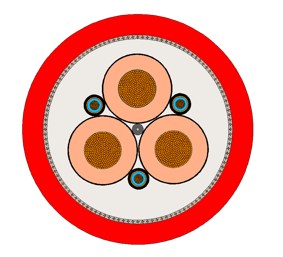
Cette construction combine trois cœurs de puissance principaux avec un double contrôle concentrique et des éléments conducteurs PE. Le câble utilise un conducteur finement étamé-cuivre, une isolation EPR 3GI3, une gaine intérieure GM1B, un armurement en acier/cuivre et une gaine extérieure en élastomère rouge 5GM5. (gm5) (pe)
| Paramètre | Valeur indiquée par la source |
|---|---|
| Conducteur principal | Conducteur en cuivre étamé finement échoué, classe FS |
| Commande / conducteur PE | Double commande concentrique / fil PE tournant dans les interstices extérieurs |
| Isolation | Composé de caoutchouc EPR de type 3GI3 |
| Contrôle du champ électrique | Couche extérieure agrafable à froid du composé de caoutchouc semi-conducteur |
| Identification des âmes | Couleur naturelle des carottes principales; contrôle des noyaux bleu |
| gaine intérieure | gaine intérieure en caoutchouc EPR vulcanisé, type de composé GM1B |
| Blindage | Filature en acier/cuivre à lame fermée entre gaine intérieure et extérieure |
| Gaine extérieure | Composé élastomère synthétique de Type 5GM5, rouge |
La voie de protection de la chaîne et l'arrangement de contrôle/PE double concentrique sont les principales distinctions de commande. Conservez la notation du noyau source dans la RFQ et vérifiez le matériel de terminaison par rapport au dessin final du câble.
Demandes pour NTSKCGECWOEU
La source décrit un câble de raccordement à l'alimentation électrique pour les équipements mobiles et les machines des mines souterraines, y compris les machines de coupe du charbon. Il est destiné aux chaînes de protection des câbles et aux gestionnaires de câbles traînant derrière la machine, où les mouvements répétés et les forces de traction doivent être absorbés.
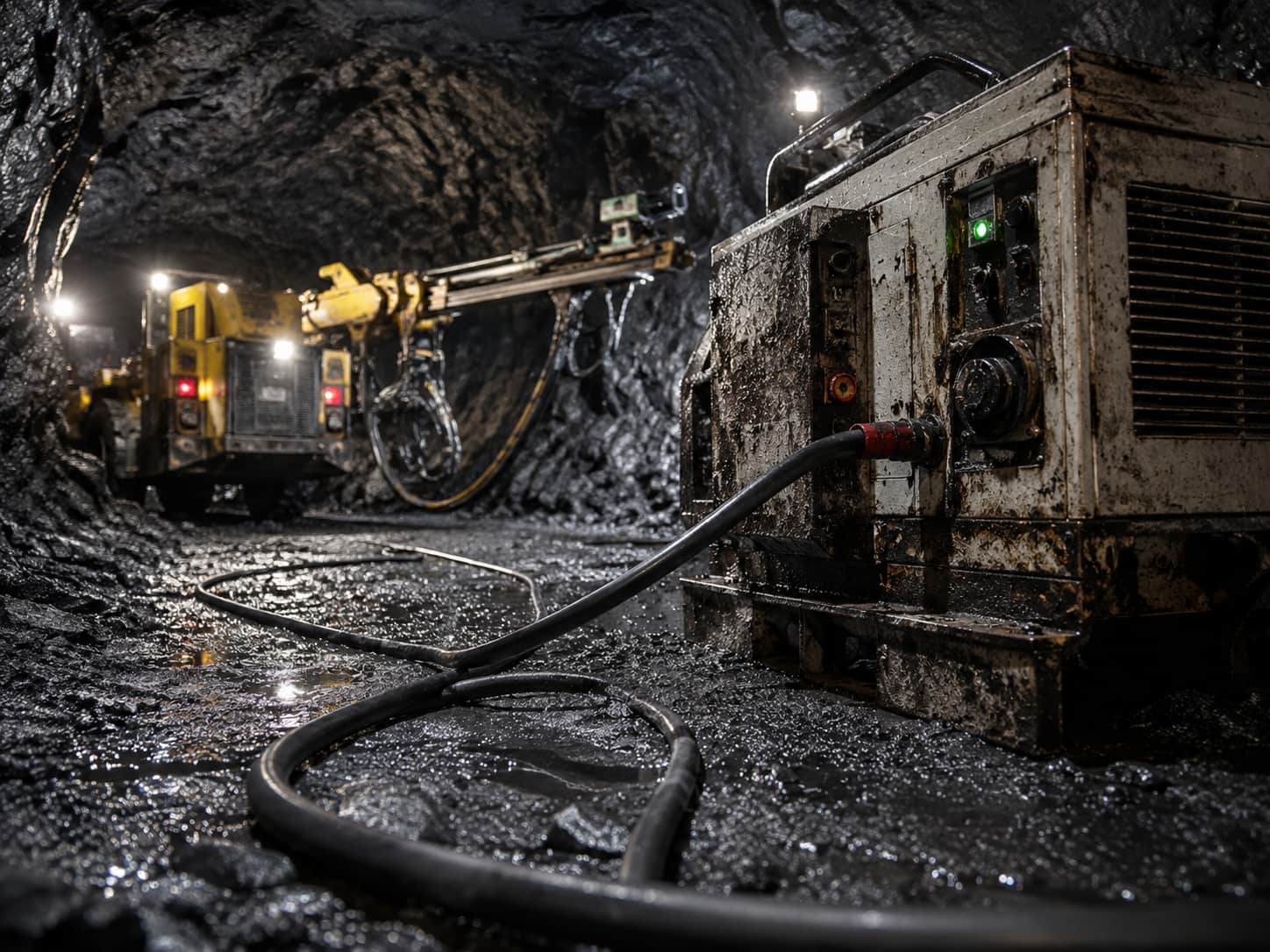
- Machines et appareils souterrains de coupe du charbon et autres équipements miniers mobiles énumérés dans la source
- Chaînes de protection de câbles et gestionnaires de câbles traînant derrière la machine
- Systèmes 1.8/3 kV et 3.6/6 kV avec trois ou six Options de base de contrôle
- Confirmerer la géométrie de la chaîne, le cycle de mouvement, la trajectoire de traction, le rayon de virage, les fonctions de base, les terminaisons et l'interface de protection avant devis
Les valeurs de flexion et de traction fournies décrivent la construction du câble; ils ne remplacent pas le calcul de la chaîne propre à la machine ni le dessin d'installation approuvé.
Spécifications NTSKCGECWOEU
Les tableaux fournis couvrent les versions 1.8/3 kV et 3.6/6 kV, avec trois ou six arrangements de base de commande. L'expression «UEL» est conservée exactement comme désignation de la source; Confirmerer son sens et le calendrier de base final du dessin approuvé.
| Paramètre | Valeur indiquée par la source |
|---|---|
| Tension assignée | 1.8/3 kV; 3.6/6 kV |
| Tension maximale admissible en service CA | 2.1/3.6 kV; 4.2/7.2 kV |
| Tension maximale admissible en service CC | 2.7/5.4 kV; 5.4/10.8 kV |
| tension d'essai CA | 6 kV pour 1.8/3 kV; 11 kV pour 3.6/6 kV |
| Tension d’essai CA — âmes de commande | 2 kV |
| Température maximale de fonctionnement du conducteur | 90 °C |
| Température maximale du conducteur en court-circuit | 250 °C |
| température d'installation fixe | −40 °C to +90 °C |
| Température de fonctionnement entièrement flexible | −20 °C to +90 °C |
| charge de traction maximale | 15 N/mm² |
| Rayon de courbure | 2.3 × D à charge maximale de traction 5 N/mm²; Distance de type S 20 × D |
| Section transversale / disposition des âmes | Diamètre extérieur du conducteur (mm) | OD min–max (mm) | Poids (kg/km) | Tension (N) | Résistance DC (γ/km) | Capacité (µF/km) | Inductance (mH/km) | Courant (A) | Circuit court (kA) |
|---|---|---|---|---|---|---|---|---|---|
| 3×25+3×(1.5ST+16/3)+UEL | 7.1 | 40.1–43.1 | 3100 | 1125 | 0.795 | 0.33 | 0.32 | 131 | 3.58 |
| 3×35+3×(1.5ST+25/3)+UEL | 8.4 | 44.3–47.3 | 3970 | 1575 | 0.565 | 0.38 | 0.30 | 162 | 5.01 |
| 3×50+3×(1.5ST+25/3)+UEL | 10.1 | 49.7–52.7 | 4900 | 2250 | 0.393 | 0.44 | 0.29 | 202 | 7.15 |
| 3×70+3×(1.5ST+35/3)+UEL | 11.9 | 53.2–57.2 | 6020 | 3150 | 0.277 | 0.50 | 0.27 | 250 | 10.01 |
| 3×95+3×(1.5ST+50/3)+UEL | 14 | 58.6–62.6 | 7450 | 4275 | 0.210 | 0.54 | 0.27 | 301 | 13.59 |
| 3×120+3×(1.5ST+70/3)+UEL | 15.5 | 62.9–66.9 | 9060 | 5400 | 0.164 | 0.58 | 0.27 | 352 | 17.16 |
| 3×150+3×(1.5ST+70/3)+UEL | 17.2 | 69–73 | 10820 | 6750 | 0.132 | 0.64 | 0.26 | 404 | 21.45 |
| 3×185+3×(1.5ST+95/3)+UEL | 19.1 | 73.2–77.2 | 12530 | 8325 | 0.108 | 0.70 | 0.25 | 461 | 26.46 |
| 3×240+3×(1.5ST+120/3)+UEL | 22 | 80.7–85.7 | 15700 | 10800 | 0.0817 | 0.79 | 0.25 | 540 | 34.32 |
| Section transversale / disposition des âmes | Diamètre extérieur du conducteur (mm) | OD min–max (mm) | Poids (kg/km) | Tension (N) | Résistance DC (γ/km) | Capacité (µF/km) | Inductance (mH/km) | Courant (A) | Circuit court (kA) |
|---|---|---|---|---|---|---|---|---|---|
| 3×25+3×(1.5ST+16/3)+UEL | 7.1 | 45–48 | 3600 | 1125 | 0.795 | 0.34 | 0.33 | 131 | 3.58 |
| 3×35+3×(1.5ST+25/3)+UEL | 8.4 | 48.3–51.3 | 4360 | 1575 | 0.565 | 0.38 | 0.31 | 162 | 5.01 |
| 3×50+3×(1.5ST+25/3)+UEL | 10.1 | 51.4–55.4 | 5320 | 2250 | 0.393 | 0.43 | 0.30 | 202 | 7.15 |
| 3×70+3×(1.5ST+35/3)+UEL | 11.9 | 56.7–60.7 | 6560 | 3150 | 0.277 | 0.49 | 0.29 | 250 | 10.01 |
| 3×95+3×(1.5ST+50/3)+UEL | 14 | 61.2–65.2 | 7890 | 4275 | 0.210 | 0.55 | 0.28 | 301 | 13.59 |
| 3×120+3×(1.5ST+70/3)+UEL | 15.5 | 67.3–71.3 | 9780 | 5400 | 0.164 | 0.60 | 0.27 | 352 | 17.16 |
| 3×150+3×(1.5ST+70/3)+UEL | 17.2 | 71.7–75.7 | 11300 | 6750 | 0.132 | 0.64 | 0.26 | 404 | 21.45 |
| 3×185+3×(1.5ST+95/3)+UEL | 19.1 | 75.1–79.1 | 12790 | 8325 | 0.108 | 0.69 | 0.25 | 461 | 26.46 |
| 3×240+3×(1.5ST+120/3)+UEL | 22 | 82.7–87.7 | 15900 | 10800 | 0.0817 | 0.77 | 0.25 | 540 | 34.32 |
| Section transversale / disposition des âmes | Diamètre extérieur du conducteur (mm) | OD min–max (mm) | Poids (kg/km) | Tension (N) | Résistance DC (γ/km) | Capacité (µF/km) | Inductance (mH/km) | Courant (A) | Circuit court (kA) |
|---|---|---|---|---|---|---|---|---|---|
| 3×35+3×(2×1.5ST+25/3)+UEL | 8.4 | 49–53 | 4620 | 1575 | 0.565 | 0.38 | 0.31 | 162 | 5.01 |
| 3×50+3×(2×1.5ST+25/3)+UEL | 10.1 | 53.9–57.9 | 5550 | 2250 | 0.393 | 0.43 | 0.30 | 202 | 7.15 |
| 3×70+3×(2×1.5ST+35/3)+UEL | 11.9 | 56.7–60.7 | 6760 | 3150 | 0.277 | 0.49 | 0.39 | 250 | 10.01 |
| 3×95+3×(2×1.5ST+50/3)+UEL | 14 | 62–66 | 7900 | 4275 | 0.210 | 0.55 | 0.28 | 301 | 13.59 |
| 3×120+3×(2×1.5ST+70/3)+UEL | 15.5 | 67.3–71.3 | 9800 | 5400 | 0.164 | 0.60 | 0.27 | 352 | 17.16 |
| 3×150+3×(2×1.5ST+70/3)+UEL | 17.2 | 71–75 | 11100 | 6750 | 0.132 | 0.64 | 0.26 | 404 | 21.45 |
| 3×185+3×(2×1.5ST+95/3)+UEL | 19.1 | 75.1–79.1 | 13000 | 8325 | 0.108 | 0.69 | 0.25 | 461 | 26.46 |
| 3×240+3×(2×1.5ST+120/3)+UEL | 22 | 82.7–87.7 | 16000 | 10800 | 0.0817 | 0.77 | 0.25 | 540 | 34.32 |
La capacité de charge actuelle est basée sur des câbles en caoutchouc posés sur une surface à température ambiante 30 °C. La source identifie les numéros d'article propres au fabricant comme omis.
Normes et performances NTSKCGECWOEU
La fiche technique fournie contient les références suivantes pour les câbles, le feu, l'huile et les conditions météorologiques.
| Paramètre | Valeur indiquée par la source |
|---|---|
| Norme du câble | DIN VDE 0250-813 |
| Comportement au feu | IEC 60332-1-2 |
| résistance à l'huile | CEI 60811-404 (iec) |
| Résistance aux intempéries | Utilisation extérieure et intérieure; résistant à l’ozone et à l’humidité |
| Tableau actuel | Câbles en caoutchouc posés sur une surface à température ambiante 30 °C |
Demander l'édition standard requise, la portée de l'inspection, le rapport d'essai et le marquage final du câble avec la commande. Aucun numéro d'article spécifique au fabricant n'est reproduit dans la page publique.
Options de câbles associées
Comparez ces options de câbles selon les fonctions requises, le mouvement, la charge, la tension et les besoins de transmission.
Câble traînant pour coupeuse de charbon NSSHKCGEOEU 0,6/1 kV
Une autre option de câble pour une application ou des conditions de service différentes.
Voir le produit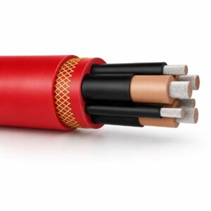
Câble minier traînant moyenne tension (N)TSKCGEWÖU 3.6/6kV
Pour le service de remorquage 3,6/6 kV derrière les équipements miniers mobiles.
Voir le produit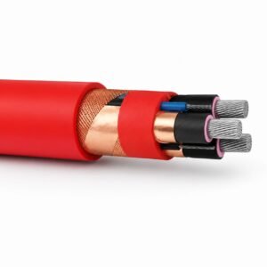
Câble d'enroulement pour tunnelier (N)TSCGECECWÖU 8.7/15kV 12/20kV
Une autre option de câble pour une application ou des conditions de service différentes.
Voir le produitDemandez une recommandation et un devis pour un câble.
Indiquez les fonctions requises, la longueur du câble, les contraintes mécaniques, l’environnement, les terminaisons et la quantité. Notre équipe évaluera l’aptitude à l’application avant d’établir une soumission.
- Veuillez inclure le nom du produit ou son SKU, ainsi que la longueur et la quantité de câble requises.
- Joignez une fiche technique, un dessin ou une fiche de spécifications si disponible.