

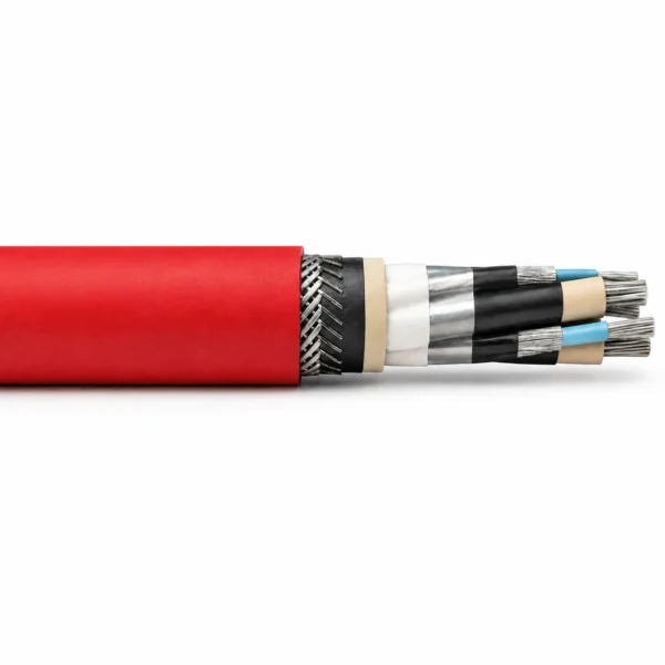
NTSKCGECWOEU 1.8/3–3.6/6 kV Coal Cutter Chain Cable
Medium-voltage coal-cutter chain cable with double concentric control/PE conductors and closed-lay steel/copper wire protection.
NTSKCGECWOEU is a medium-voltage coal-cutter chain cable for underground mobile mining equipment, coal-cutting machines, cable protection chains and trailing cable handlers. The supplied VDE datasheet specifies finely stranded tinned copper conductors, 3GI3 EPR insulation, cold-strippable semiconductive field control, double concentric control and PE wire elements, a GM1B inner sheath, closed-lay steel and copper wire protection and a red 5GM5 synthetic elastomer outer sheath. The technical tables cover 1.8/3 kV and 3.6/6 kV systems, with three-control and six-control arrangements and conductor configurations from 25 mm² through 240 mm². The source lists 90 °C conductor operation, 250 °C short-circuit temperature, fixed service from −40 °C to +90 °C and fully flexible service from −20 °C to +90 °C. Chain geometry, movement cycles, tensile path, bending radius, core functions, UEL notation and termination hardware must be checked against the machine drawing. Use the size table together with the machine duty cycle and installation layout; cable selection should be approved against the chain travel, support spacing and connector system. Request the required configuration, size, length and test documents from TEBAOFLEX before release.
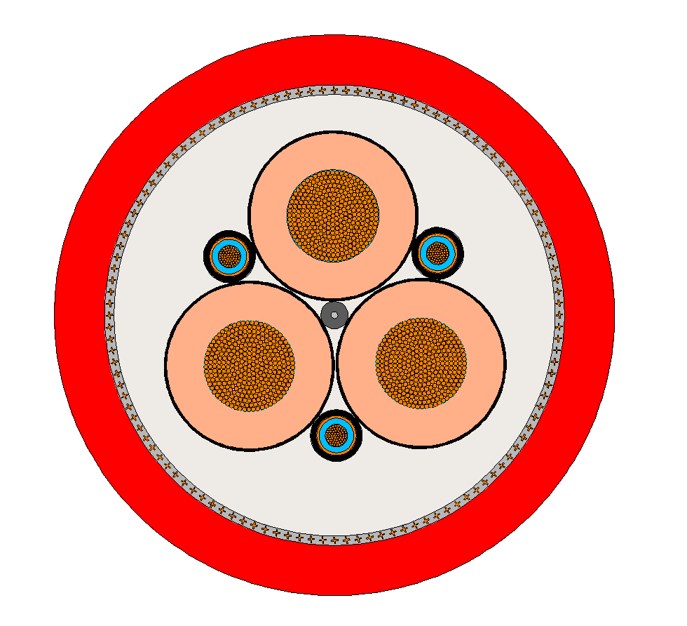
NTSKCGECWOEU chain-cable construction
This construction combines three main power cores with double concentric control and PE conductor elements. The cable uses a finely stranded tinned-copper conductor, 3GI3 EPR insulation, an inner GM1B sheath, closed-lay steel/copper wire armouring and a red 5GM5 elastomer outer sheath.
| Parameter | Source-listed value |
|---|---|
| Main conductor | Finely stranded tinned copper conductor, class FS |
| Control / PE conductor | Double concentric control / PE wire spinning in the outer interstices |
| Insulation | EPR rubber compound type 3GI3 |
| Electrical field control | Cold-strippable outer layer of semiconductive rubber compound |
| Core identification | Main cores natural colour; control cores blue |
| Inner sheath | Vulcanized EPR rubber inner sheath, compound type GM1B |
| Armouring | Closed-lay spinning of steel / copper wires between inner and outer sheath |
| Outer sheath | Synthetic elastomer compound type 5GM5, red |
The chain-protection route and the double-concentric control/PE arrangement are the key ordering distinctions. Keep the source core notation in the RFQ and verify the termination hardware against the final cable drawing.
Applications for NTSKCGECWOEU
The source describes a power-supply connection cable for mobile equipment and machines in underground mining, including coal-cutting machines. It is intended for cable protection chains and cable handlers trailed behind the machine, where repeated movement and tensile forces must be absorbed.
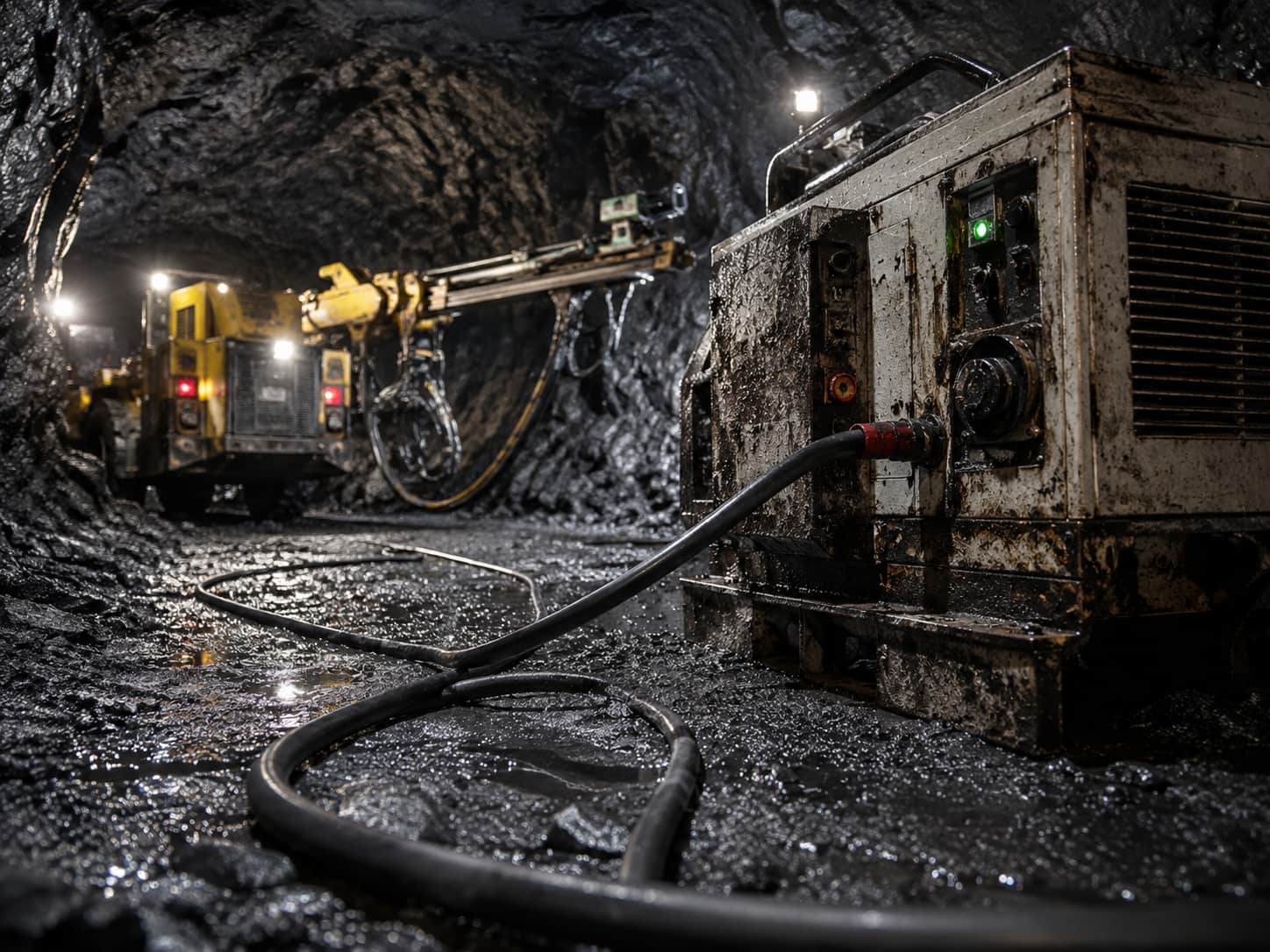
- Underground coal-cutting machines and other mobile mining equipment listed in the source
- Cable protection chains and cable handlers trailed behind the machine
- 1.8/3 kV and 3.6/6 kV systems with three- or six-control-core table options
- Confirm chain geometry, movement cycle, tensile path, bend radius, core functions, terminations and protection interface before quotation
The supplied bending and tensile values describe the cable construction; they do not replace the machine-specific chain calculation or the approved installation drawing.
NTSKCGECWOEU specifications
The supplied tables cover 1.8/3 kV and 3.6/6 kV versions, with either three or six control-core arrangements. “UEL” is retained exactly as the source designation; confirm its meaning and the final core schedule on the approved order drawing.
| Parameter | Source-listed value |
|---|---|
| Rated voltage | 1.8/3 kV; 3.6/6 kV |
| Maximum permissible AC operating voltage | 2.1/3.6 kV; 4.2/7.2 kV |
| Maximum permissible DC operating voltage | 2.7/5.4 kV; 5.4/10.8 kV |
| AC test voltage | 6 kV for 1.8/3 kV; 11 kV for 3.6/6 kV |
| AC test voltage — control cores | 2 kV |
| Maximum conductor operating temperature | 90 °C |
| Maximum short-circuit conductor temperature | 250 °C |
| Fixed installation temperature | −40 °C to +90 °C |
| Fully flexible operation temperature | −20 °C to +90 °C |
| Maximum tensile load | 15 N/mm² |
| Bending radius | 2.3 × D at maximum 5 N/mm² tensile load; S-type distance 20 × D |
| Cross-section / core arrangement | Conductor OD (mm) | OD min–max (mm) | Weight (kg/km) | Tensile (N) | DC resistance (Ω/km) | Capacitance (µF/km) | Inductance (mH/km) | Current (A) | Short-circuit (kA) |
|---|---|---|---|---|---|---|---|---|---|
| 3×25+3×(1.5ST+16/3)+UEL | 7.1 | 40.1–43.1 | 3100 | 1125 | 0.795 | 0.33 | 0.32 | 131 | 3.58 |
| 3×35+3×(1.5ST+25/3)+UEL | 8.4 | 44.3–47.3 | 3970 | 1575 | 0.565 | 0.38 | 0.30 | 162 | 5.01 |
| 3×50+3×(1.5ST+25/3)+UEL | 10.1 | 49.7–52.7 | 4900 | 2250 | 0.393 | 0.44 | 0.29 | 202 | 7.15 |
| 3×70+3×(1.5ST+35/3)+UEL | 11.9 | 53.2–57.2 | 6020 | 3150 | 0.277 | 0.50 | 0.27 | 250 | 10.01 |
| 3×95+3×(1.5ST+50/3)+UEL | 14 | 58.6–62.6 | 7450 | 4275 | 0.210 | 0.54 | 0.27 | 301 | 13.59 |
| 3×120+3×(1.5ST+70/3)+UEL | 15.5 | 62.9–66.9 | 9060 | 5400 | 0.164 | 0.58 | 0.27 | 352 | 17.16 |
| 3×150+3×(1.5ST+70/3)+UEL | 17.2 | 69–73 | 10820 | 6750 | 0.132 | 0.64 | 0.26 | 404 | 21.45 |
| 3×185+3×(1.5ST+95/3)+UEL | 19.1 | 73.2–77.2 | 12530 | 8325 | 0.108 | 0.70 | 0.25 | 461 | 26.46 |
| 3×240+3×(1.5ST+120/3)+UEL | 22 | 80.7–85.7 | 15700 | 10800 | 0.0817 | 0.79 | 0.25 | 540 | 34.32 |
| Cross-section / core arrangement | Conductor OD (mm) | OD min–max (mm) | Weight (kg/km) | Tensile (N) | DC resistance (Ω/km) | Capacitance (µF/km) | Inductance (mH/km) | Current (A) | Short-circuit (kA) |
|---|---|---|---|---|---|---|---|---|---|
| 3×25+3×(1.5ST+16/3)+UEL | 7.1 | 45–48 | 3600 | 1125 | 0.795 | 0.34 | 0.33 | 131 | 3.58 |
| 3×35+3×(1.5ST+25/3)+UEL | 8.4 | 48.3–51.3 | 4360 | 1575 | 0.565 | 0.38 | 0.31 | 162 | 5.01 |
| 3×50+3×(1.5ST+25/3)+UEL | 10.1 | 51.4–55.4 | 5320 | 2250 | 0.393 | 0.43 | 0.30 | 202 | 7.15 |
| 3×70+3×(1.5ST+35/3)+UEL | 11.9 | 56.7–60.7 | 6560 | 3150 | 0.277 | 0.49 | 0.29 | 250 | 10.01 |
| 3×95+3×(1.5ST+50/3)+UEL | 14 | 61.2–65.2 | 7890 | 4275 | 0.210 | 0.55 | 0.28 | 301 | 13.59 |
| 3×120+3×(1.5ST+70/3)+UEL | 15.5 | 67.3–71.3 | 9780 | 5400 | 0.164 | 0.60 | 0.27 | 352 | 17.16 |
| 3×150+3×(1.5ST+70/3)+UEL | 17.2 | 71.7–75.7 | 11300 | 6750 | 0.132 | 0.64 | 0.26 | 404 | 21.45 |
| 3×185+3×(1.5ST+95/3)+UEL | 19.1 | 75.1–79.1 | 12790 | 8325 | 0.108 | 0.69 | 0.25 | 461 | 26.46 |
| 3×240+3×(1.5ST+120/3)+UEL | 22 | 82.7–87.7 | 15900 | 10800 | 0.0817 | 0.77 | 0.25 | 540 | 34.32 |
| Cross-section / core arrangement | Conductor OD (mm) | OD min–max (mm) | Weight (kg/km) | Tensile (N) | DC resistance (Ω/km) | Capacitance (µF/km) | Inductance (mH/km) | Current (A) | Short-circuit (kA) |
|---|---|---|---|---|---|---|---|---|---|
| 3×35+3×(2×1.5ST+25/3)+UEL | 8.4 | 49–53 | 4620 | 1575 | 0.565 | 0.38 | 0.31 | 162 | 5.01 |
| 3×50+3×(2×1.5ST+25/3)+UEL | 10.1 | 53.9–57.9 | 5550 | 2250 | 0.393 | 0.43 | 0.30 | 202 | 7.15 |
| 3×70+3×(2×1.5ST+35/3)+UEL | 11.9 | 56.7–60.7 | 6760 | 3150 | 0.277 | 0.49 | 0.39 | 250 | 10.01 |
| 3×95+3×(2×1.5ST+50/3)+UEL | 14 | 62–66 | 7900 | 4275 | 0.210 | 0.55 | 0.28 | 301 | 13.59 |
| 3×120+3×(2×1.5ST+70/3)+UEL | 15.5 | 67.3–71.3 | 9800 | 5400 | 0.164 | 0.60 | 0.27 | 352 | 17.16 |
| 3×150+3×(2×1.5ST+70/3)+UEL | 17.2 | 71–75 | 11100 | 6750 | 0.132 | 0.64 | 0.26 | 404 | 21.45 |
| 3×185+3×(2×1.5ST+95/3)+UEL | 19.1 | 75.1–79.1 | 13000 | 8325 | 0.108 | 0.69 | 0.25 | 461 | 26.46 |
| 3×240+3×(2×1.5ST+120/3)+UEL | 22 | 82.7–87.7 | 16000 | 10800 | 0.0817 | 0.77 | 0.25 | 540 | 34.32 |
Current carrying capacity is based on rubber cables laid on a surface at 30 °C ambient temperature. The source identifies manufacturer-specific article numbers as omitted.
NTSKCGECWOEU standards and performance
The supplied datasheet lists the following cable standard, fire, oil and weather-performance references.
| Parameter | Source-listed value |
|---|---|
| Cable standard | DIN VDE 0250-813 |
| Fire performance | IEC 60332-1-2 |
| Oil resistance | IEC 60811-404 |
| Weather resistance | Outdoor and indoor use; resistant to ozone and moisture |
| Current-table basis | Rubber cables laid on a surface at 30 °C ambient temperature |
Request the required standard edition, inspection scope, test report and final cable marking with the order. No manufacturer-specific article numbers are reproduced in the public page.
Related cable options
Compare these cable options by service combination, movement, load, voltage and transmission requirement.
NSSHKCGEOEU 0.6/1kV Coal Cutter Trailing Cable
A related cable option for a different application or duty profile.
View product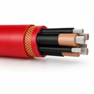
(N)TSKCGEWÖU 3.6/6kV Medium Voltage Mining Trailing Cable
For 3.6/6 kV trailing duty behind mobile mining equipment.
View product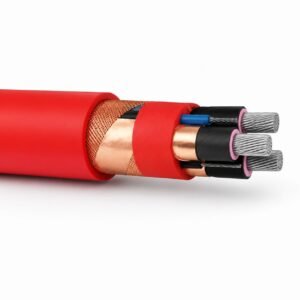
(N)TSCGECECWÖU 8.7/15kV 12/20kV TBM Reeling Cable
A related cable option for a different application or duty profile.
View productRequest a cable recommendation and quotation
Send the required services, cable length, mechanical duty, environment, termination and quantity. Our team will review the application before quoting.
- Include the product name or SKU plus the required cable length and quantity.
- Attach a specification, drawing or data sheet when available.