

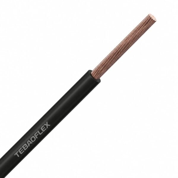
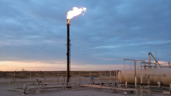

Flare Stack Ignition Cable 25 kV DC / 10 kV AC, 250°C
High-voltage igniter cable for flare stacks, flare pilots and incinerator igniters. Unscreened single core, made to run length.
- Rating: 25 kV DC / 10 kV AC
- Temperature: −60 °C to +250 °C maximum conductor temperature
- Conductor: finely stranded nickel-plated copper, 22 AWG to 10 AWG
- Insulation: high-voltage silicone rubber + mica tape wrap
- Jacket: impregnated fiberglass braid with fluoropolymer outer coat
- Bend radius: 10 × OD static, 12 × OD dynamic
- Options: fluoropolymer-jacketed version without braid; stainless-steel braid or interlocked armour on request
Send the stack height, exciter output and terminal detail for a quotation that covers cable, gland size and terminations.
A flare stack ignition cable has one job: carry the spark from the exciter cabinet at grade to the igniter rod at the flare tip, every time, for years, in the worst heat and weather on the plant. TEBAOFLEX builds it rated 25 kV DC / 10 kV AC with a maximum conductor temperature of 250 °C, in 22 AWG through 10 AWG, cut to the run length you need.
The construction is five layers and every one of them is load-bearing. Finely stranded nickel-plated copper survives the temperature that would oxidise a tinned conductor. A high-voltage silicone rubber wall provides the dielectric strength and stays flexible enough to be pulled up a stack in winter. A mica tape wrap holds the geometry when the silicone is at the top of its range. An impregnated fiberglass braid takes the abrasion of conduit, clamps and ladder cages. A fluoropolymer outer coat keeps water, salt and hydrocarbon out of that braid. Delete any one layer and you get the failure this cable exists to prevent.
It is an unscreened single core. It is not a screened medium-voltage power cable, not a thermocouple or flame-rod lead, and not a general-purpose high temperature wire — those sit elsewhere in our high temperature cable range and in the wider oil and gas cable programme.
Tell us the stack height, the exciter output and how the cable is terminated at both ends, and we will quote the run length, the gland size and the terminations together instead of quoting metres of cable and leaving you to work out the rest.
For an ignition lead inside protected equipment, review UL 3257 silicone ignition wire. Its stated AC/DC ratings do not by themselves establish suitability for an exposed flare-stack run; weather, vertical support, braid, glands and terminations require separate review.
Five layers, and none of them is decoration. A flare stack attacks cable four ways at once — heat, high voltage, abrasion and water — and no single material answers all four. Read the build from the copper outwards and each layer explains itself.
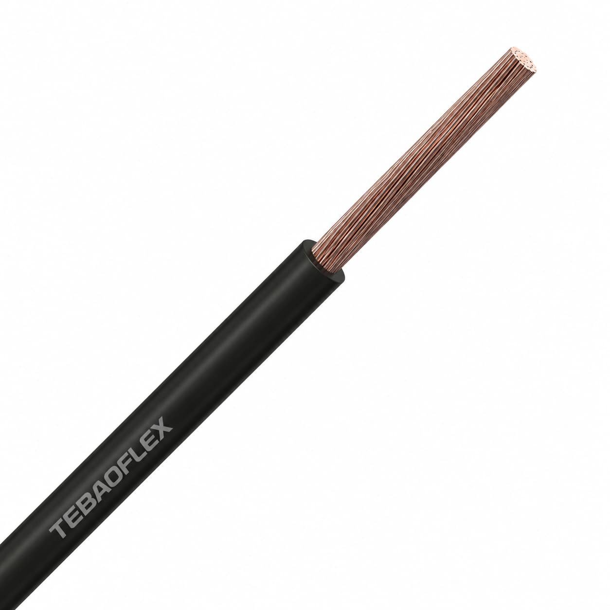
- Conductor: finely stranded nickel-plated copper, 22 AWG to 10 AWG. Fine stranding is what lets a cable this stiff be pulled up a stack and dressed into a junction box without a broken strand starting a hot spot.
- Insulation: a high-voltage silicone rubber wall. This is the whole dielectric system — the layers outside it are mechanical and environmental, not electrical.
- Barrier: a mica tape wrap over the silicone. Mica is inorganic; it holds its shape and its insulating value at temperatures where the silicone is already at the top of its range.
- Braid: an impregnated fiberglass braid, finished with a high-temperature compound so it does not fray when it is cut and glanded.
- Outer coat: a fluoropolymer coating over the braid. It is thin, and it is the only thing standing between the braid and rain, salt spray, condensate and hydrocarbon.
Why nickel-plated copper, and not tinned
Plating is not cosmetic on a 250 °C cable. Tin is the default plating on ordinary hook-up wire and it is the wrong choice here: it softens and oxidises long before the conductor reaches its rating, and an oxidised strand surface at a crimp is where resistance — and heat — starts. Nickel keeps a solderable, low-oxide surface across the whole 250 °C range and well beyond it, which is why every serious igniter cable uses it. If a quotation for a flare stack cable offers tinned copper, that is the tell.
The fiberglass braid is not a screen
It looks like a braid on a screened cable and it is nothing of the sort. There is no metallic screen in this construction and no drain wire, because a screen around a 25 kV ignition conductor would give the discharge somewhere to go that is not the igniter rod. The braid is mechanical armour and a heat barrier. Do not bond it, do not terminate it as if it were a shield, and do not specify this cable where a screened high-voltage cable is what the drawing actually calls for.
Two outer builds, and when each one is right
The braided build above is the default because most flare stacks are an abrasion problem: conduit edges, clamps, ladder cages, and a cable that moves in the wind for twenty years. Where the run is short, well protected and the real threat is chemical — acid gas, solvent washdown, heavy condensate — a fluoropolymer-jacketed version without the braid is the better answer: smaller outside diameter, better chemical resistance, less abrasion resistance. For offshore and marine stacks, a stainless-steel braid or interlocked armour can be added over the fluoropolymer. Tell us which of the three threats dominates on your stack and we will tell you which build to buy.
Bend radius decides whether the pull succeeds
Static 10 × cable OD, dynamic 12 × cable OD. These are larger multiples than a control cable because the silicone wall is thick and the mica tape underneath it does not tolerate being creased — a kink that looks cosmetic can crack the mica and leave a weak point that only shows up as a misfire months later. Size the sheaves, the conduit sweeps and the junction box entries from the finished OD in the table on the Specifications tab, not from the conductor size.
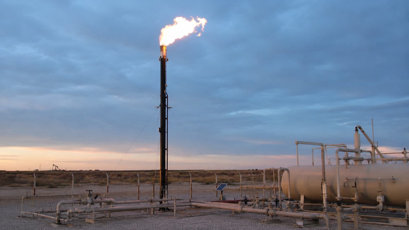
This cable lives on the outside of a plant, vertically, in the weather, at the one place nobody wants to send a technician: the top of a flare stack. Everything about the specification follows from that.
Where it is used
- Flare stack igniters — the high-voltage run from the exciter cabinet at grade to the igniter rod at the tip, on elevated, ground and enclosed flares.
- Flare pilot ignition — continuous and intermittent pilots, including retractable pilot assemblies.
- Incinerator and thermal oxidiser igniters — same duty, shorter run, usually hotter at the terminal end.
- Burner and boiler high-energy ignition — process heaters, reformers and package boilers using spark-rod ignition.
- Portable and skid-mounted flare packages — well-test and rental flares, where the cable is coiled and re-run repeatedly and flex life matters more than anything else.
- Landfill gas and biogas flares — lower temperature at the tip, but a corrosive, wet atmosphere that finds every jacket defect.
Where flare stack cable actually fails
Ignition problems on a flare are blamed on the exciter far more often than the exciter deserves. The dominant cause of failure in this cable is not heat and not voltage — it is water. Water gets into the braid through a nicked coat or an unsealed termination, wicks along the cable, collects at the low point, and gives the discharge a path it likes better than the rod. The symptom is intermittent ignition; the cause is a junction box with no drain.
- Drain the low points. Every conduit low point and every junction box that can collect condensate needs a drain. This is the single highest-value thing on this list.
- Let the current pick the rod, not the box. A poor splice or a wet gland is an easier path than the igniter tip, and 25 kV will take it. If the spark is audible at the junction box, stop looking at the exciter.
- Strain-relieve the vertical run. On a hundred-foot stack the cable is hanging from its own termination. Ring lugs and proper strain relief, not the conductor, should carry that weight.
- Deburr the conduit. A sharp conduit edge will cut the fluoropolymer coat during the pull and the damage will not be visible from either end.
- Do not pull several cables through one small-bore pipe with tight bends. The braid protects against abrasion; it does not protect against being dragged around a 90° elbow under tension.
- Oversize the junction box. Cables entering from the side and leaving through the top drain naturally and can be dressed to the bend radius. A tight box forces a kink.
What else runs up the same stack
An ignition circuit is one of three cable systems on a flare, and they are usually specified together: the high-voltage igniter cable on this page, a thermocouple or flame-rod lead that proves the pilot is lit, and instrumentation or data cable for flow metering at the header. They share the same temperature and weather exposure but almost nothing else — different voltage class, different screening, different standards. See the oil and gas cable range and the oil, gas and petrochemical overview for the rest of the package, and send the full stack list if you would rather quote it in one go.
What this cable is not for
- Not a screened HV cable. No metallic screen, no drain wire. If the specification requires a bonded screen, this is the wrong product.
- Not equipment internal wiring. For high-voltage leads inside the exciter cabinet or an X-ray, imaging or test set, use high voltage silicone wire in UL 3239 or UL 10475.
- Not a 538 °C igniter lead. Where the conductor at the rod goes above 250 °C, the silicone wall is out of its range — use 25 kV igniter wire in the mica and fiberglass build instead.
- Not an engine ignition lead. Gas engines, gensets and burner spark leads at 7–10 kV are a different, lighter build — see 7–10 kV silicone ignition cable and Style 3304 / 3573 10 kV ignition wire.
- Not a thermocouple extension. Flame proving uses a matched thermocouple pair; a high-voltage single core cannot substitute for it.
- Not a substitute for the offshore jacket spec. Where NEK 606 mud-resistant or low-smoke sheathing is mandated, that is a different jacket system — ask before assuming this build qualifies.
Ratings
| Property | Value |
|---|---|
| Voltage rating, DC | 25 kV DC |
| Voltage rating, AC | 10 kV AC |
| Maximum conductor temperature | 250 °C (482 °F) |
| Minimum temperature | −60 °C (installed); confirm for cold pulling below −40 °C |
| Conductor size range | 22 AWG – 10 AWG (0.32 – 5.26 mm²) |
| Cores | Single core, unscreened |
| Bend radius, static | 10 × cable OD |
| Bend radius, dynamic | 12 × cable OD |
| Length | Made to run length; supplied as one continuous piece wherever the stack allows |
Materials
| Layer | Material | Function |
|---|---|---|
| Conductor | Finely stranded nickel-plated copper | Flex life and a stable, low-oxide surface at 250 °C |
| Insulation | High-voltage silicone rubber | The complete dielectric system |
| Barrier | Mica tape wrap | Inorganic reinforcement at the top of the temperature range |
| Braid | Impregnated fiberglass braid | Abrasion resistance and heat barrier; not a screen |
| Outer coat | Fluoropolymer coating | Water, salt and hydrocarbon barrier over the braid |
Typical finished dimensions
| AWG | Conductor (mm²) | Typical OD (mm) | Typical OD (in) | Typical weight (kg/km) |
|---|---|---|---|---|
| 22 | 0.32 | 5.2 | 0.206 | Confirm |
| 20 | 0.52 | 6.0 | 0.235 | Confirm |
| 18 | 0.82 | 6.1 | 0.239 – 0.240 | 51 |
| 16 | 1.31 | 6.4 – 6.6 | 0.251 – 0.260 | 60 |
| 14 | 2.08 | 6.9 – 7.0 | 0.270 – 0.276 | 74 |
| 12 | 3.31 | 7.4 – 7.7 | 0.290 – 0.302 | 94 |
| 10 | 5.26 | 8.6 | 0.339 | 124 |
How to read this table. There is no published standard that fixes the outside diameter of a flare stack ignition cable, so the figures above are the typical envelope for this construction rather than a specification. They are worth having anyway: independently built cables of this type land within about a quarter of a millimetre of each other at every common size, which is close enough to choose a gland and a conduit fill from. Where a cell reads Confirm, we have not verified that value to the standard we hold for published data and will issue it with the drawing. TEBAOFLEX confirms the finished OD and weight on the approved construction drawing before production — size the gland from that drawing, not from this page.
Options
| Option | What changes | When to take it |
|---|---|---|
| Fluoropolymer jacket, no braid | Smaller OD, better chemical resistance, lower abrasion resistance | Short, protected runs where chemical attack is the dominant threat |
| Stainless-steel braid | Metallic mechanical armour over the fluoropolymer | Offshore and marine stacks, rodent or impact exposure |
| Interlocked armour | Galvanised steel interlocked armour | Where the specification calls for armoured cable on the stack run |
| Terminations | Ring lugs, boots and gland assemblies fitted and tested | Whenever the ends matter more than the metres — which on a flare is always |
What governs this cable, and what does not
| Reference | Scope | How it applies here |
|---|---|---|
| UL AWM Style 1911 | High-voltage appliance wiring material, nickel-plated copper, fluoropolymer insulated, 250 °C, rated to 25 kV DC and above | Covers the fluoropolymer-insulated variant of this cable class. Ask for it by style number if your specification needs a listed product. |
| — (no UL style) | Silicone + mica + fiberglass braid + fluoropolymer coat | The braided flare stack build is a factory-rated construction. No AWM style describes it, and any supplier who quotes one for it is quoting the wrong product. |
| API 537 / ISO 25457 | Flare details and flare systems for refinery and petrochemical service | Governs the flare and its ignition system, not the cable. The cable is specified by the ignition system supplier against these system requirements. |
| NEK 606 | Cable requirements for offshore installations — mud resistance, low smoke, halogen free | A different jacket system. If your stack is offshore and NEK 606 is mandated, say so at enquiry rather than assuming this build qualifies. |
| Routine applied-voltage test | Factory test on every production length | Each length is voltage tested before despatch and the record ships with the reel. |
25 kV DC and 10 kV AC: which number applies to you
Both numbers describe the same cable, and buyers routinely quote the wrong one. The DC figure is the higher one because the ignition event is a short, high-crest discharge from the exciter, and DC withstand in a solid dielectric is the property that governs it. The AC figure is lower because sustained power-frequency stress is a harsher duty on the same wall. Specify against what your exciter actually produces: if it is a capacitive-discharge or high-energy DC exciter, the 25 kV number is your headroom; if the ignition transformer delivers a continuous AC arc, work to 10 kV and do not borrow the DC figure. Taking the larger number because it is printed on the same datasheet is the most common specification error we see on this product.
Why there is no style number to hide behind
On a hook-up wire, a UL style number fixes the material, the wall, the temperature and the voltage, and two suppliers quoting the same style are quoting comparable products. That is not true here. Flare stack cable is built to a construction description, and the differences between suppliers — braid coverage, mica layers, coat thickness, plating percentage — are exactly the differences that decide whether it survives ten winters on a stack. When you compare quotations, compare the layer list and the plating, not the price per metre. And ask for the drawing before the order, not after.
What we need from you to quote
- Stack height and the routed run length, including the drop into the exciter cabinet
- Exciter output — DC or AC, and the kV figure
- AWG, or the current and the run length so we can pick one
- Termination detail at both ends: rod stud size, lug type, gland thread and NPT size
- Environment: offshore or onshore, chemical exposure, minimum ambient
TEBAOFLEX certification
Jiangsu TEBAOFLEX Special Cable Co., Ltd holds UL certificate UL-US-2449012-0 and cUL certificate UL-CA-2437036-0, both dated 27 December 2024 under report E542560-20241225, and VDE certificate 40060055 dated 28 March 2025. These are company-level certifications. Send the build, kV class and size you intend to order and we will confirm the approval scope that applies to it before you commit.
Documentation supplied with an order
- Construction drawing with confirmed finished OD and weight for the agreed build and size
- Routine test records for the production batch, including the applied voltage test
- Certificate of conformity referencing the agreed construction and ratings
- Reel and packing list with marking and run-length detail
For the scope of a specific standard, consult the issuing body directly — UL Solutions for AWM styles, API for flare system requirements.
Related cable options
Compare these cable options by service combination, movement, load, voltage and transmission requirement.
High Voltage Silicone Wire, 3–60 kV DC
A related cable option for a different application or duty profile.
View product
7/10 kV Silicone Ignition Cable
A related cable option for a different application or duty profile.
View product
Style 3304 & Style 3573 10 kV Silicone Ignition Wire
A related cable option for a different application or duty profile.
View productRequest a cable recommendation and quotation
Send the required services, cable length, mechanical duty, environment, termination and quantity. Our team will review the application before quoting.
- Include the product name or SKU plus the required cable length and quantity.
- Attach a specification, drawing or data sheet when available.