

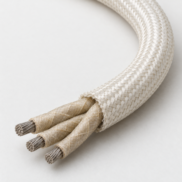
Multicore Mica-Glass High-Temperature Cable, 450°C 600 V
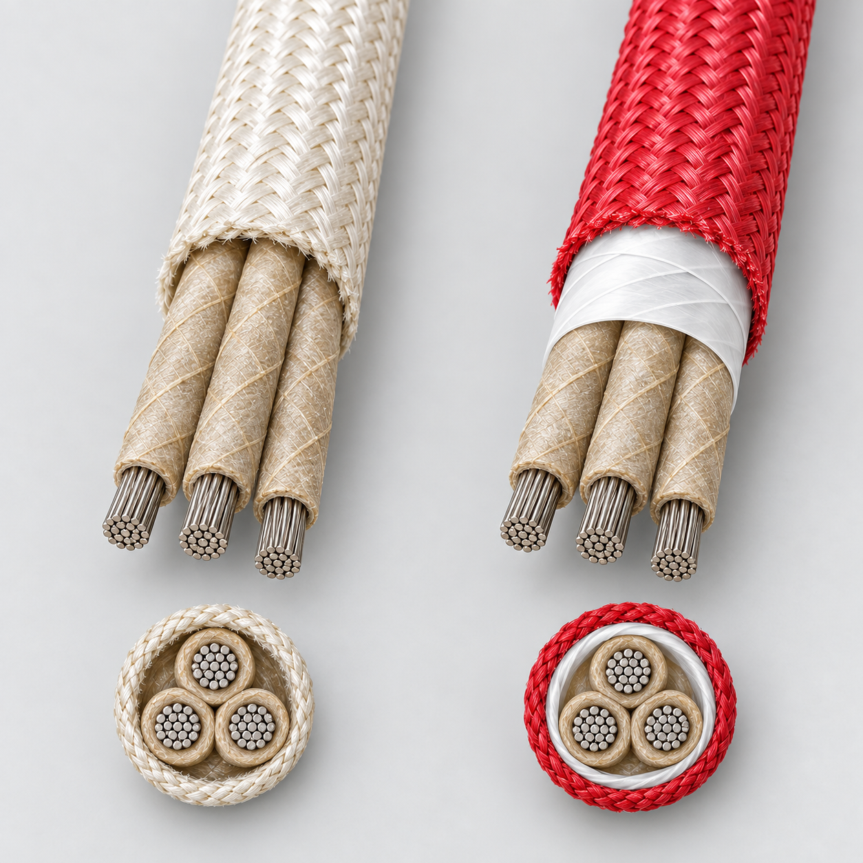
Multicore mica/glass-insulated cable with a finished fiberglass outer braid for 450°C, 600 V equipment wiring. A PTFE-tape moisture-barrier construction is shown separately.
This 450°C, 600 V multicore mica-glass cable groups two or more high-temperature conductors within a finished fiberglass outer braid. In the base construction, each conductor is flexible stranded, 27% nickel-coated annealed copper with glass-reinforced mica tape insulation. The supplied configuration table includes 18 AWG in three and four cores, 14 AWG in three and five cores, and 12 AWG in two and three cores. The combination of core count and AWG determines the overall diameter and cable weight, so a single-core mica-glass wire is not an equivalent substitute when the drawing requires one multicore assembly. Related high-temperature cable constructions: High Temperature Cables.
A second supplied construction adds skived PTFE tape as a moisture barrier over the mica/glass thermal barrier and uses a red finished fiberglass outer braid. Its table covers two to seven cores in selected 14 and 12 AWG sizes, plus a four-core 10 AWG option. The PTFE layer is a construction distinction, not a claim that every base MG configuration has the same moisture barrier. Quote the required layer sequence and core count rather than ordering only by the broad term “MG cable.”
Typical buying contexts include internal wiring of ovens, cooking equipment, cement-kiln equipment, glass plants and other hot machinery where a multicore harness is needed. Compare the single-core MGT wire and UL 5359 wire when the design specifies one lead rather than a grouped multicore cable. Confirm conductor size, core identification and any approval requirement on the drawing.
Base multicore mica-glass construction
- Flexible stranded, 27% nickel-coated annealed copper conductors.
- Glass-reinforced mica tape insulation on individual conductors.
- Two or more insulated conductors cabled into a core.
- Finished fiberglass braid as the outer covering.
PTFE moisture-barrier configuration
The second supplied construction has nickel-coated copper, mica/glass thermal tape, skived PTFE tape as a moisture barrier, a cabled core and a finished red fiberglass outer braid. This layer sequence is shown as a separate option because the base MG table does not identify a PTFE barrier.
Hot equipment with multiple circuits
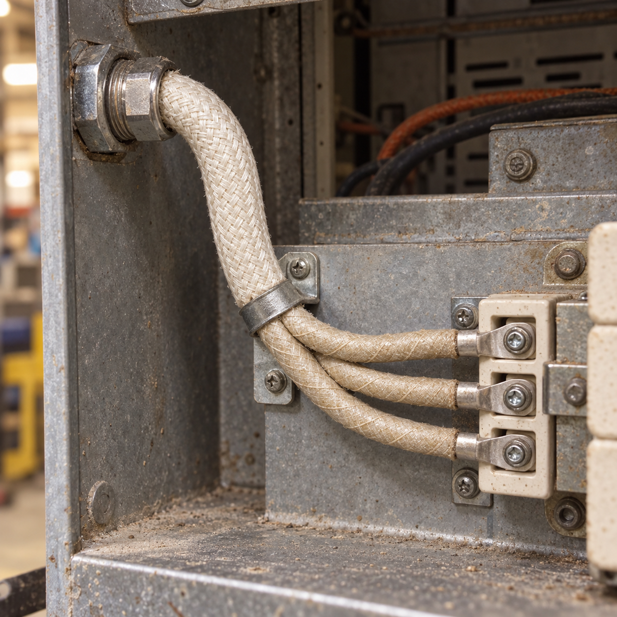
The base construction is intended for internal wiring of domestic and commercial ovens, cooking equipment, iron and steel processing equipment, cement-kiln equipment and glass-plant machinery. The PTFE moisture-barrier configuration is an option when the design specifically calls for that added layer. Neither construction should be treated as a repeatedly flexing cable simply because the conductors are stranded.
Selection question: does the drawing call for a single lead, several separately routed leads, or one multicore cable with an exact core identification scheme? Select AWG, core count, OD, thermal exposure and barrier construction together.
Base MG multicore construction, 450°C / 600 V
Nominal dimensions from the supplied source. Thickness and OD are inches; weight is lb per 1,000 ft.
| Configuration | AWG | Cores | Strands/core | Mica-glass insulation wall (in) | Outer braid wall (in) | Nominal OD (in) | Approx. weight (lb/1,000 ft) | Mica-glass wall ≈ (mm) | Outer braid wall ≈ (mm) | Nominal OD ≈ (mm) | Approx. mass ≈ (kg/km) |
|---|---|---|---|---|---|---|---|---|---|---|---|
| MG 18 AWG × 3C, 450°C 600 V multicore cable | 18 | 3 | 16 | 0.025 | 0.007 | 0.327 | 55 | 0.64 mm | 0.18 mm | 8.31 mm | 82 kg/km |
| MG 18 AWG × 4C, 450°C 600 V multicore cable | 18 | 4 | 16 | 0.025 | 0.007 | 0.345 | 69 | 0.64 mm | 0.18 mm | 8.76 mm | 103 kg/km |
| MG 14 AWG × 3C, 450°C 600 V multicore cable | 14 | 3 | 41 | 0.025 | 0.017 | 0.390 | 93 | 0.64 mm | 0.43 mm | 9.91 mm | 138 kg/km |
| MG 14 AWG × 5C, 450°C 600 V multicore cable | 14 | 5 | 41 | 0.025 | 0.017 | 0.469 | 147 | 0.64 mm | 0.43 mm | 11.91 mm | 219 kg/km |
| MG 12 AWG × 2C, 450°C 600 V multicore cable | 12 | 2 | 65 | 0.025 | 0.017 | 0.400 | 87 | 0.64 mm | 0.43 mm | 10.16 mm | 129 kg/km |
| MG 12 AWG × 3C, 450°C 600 V multicore cable | 12 | 3 | 65 | 0.025 | 0.017 | 0.426 | 120 | 0.64 mm | 0.43 mm | 10.82 mm | 179 kg/km |
PTFE moisture-barrier option, 450°C / 600 V
The source specifies an overall mica/glass thermal-barrier wall and a separate skived PTFE moisture layer but does not give a numeric PTFE layer thickness. Bend radius is the source-listed value in inches.
| Configuration | AWG | Cores | Stranding | Thermal-barrier wall (in) | Nominal OD (in) | Bend radius (in) | Approx. weight (lb/1,000 ft) | Thermal-barrier wall ≈ (mm) | Nominal OD ≈ (mm) | Bend radius ≈ (mm) | Approx. mass ≈ (kg/km) |
|---|---|---|---|---|---|---|---|---|---|---|---|
| PTFE moisture-barrier 14 AWG × 2C, 450°C 600 V multicore cable | 14 | 2 | 41 × 0.0100 | 0.025 | 0.340 | 2.71 | 85 | 0.64 mm | 8.64 mm | 68.83 mm | 126 kg/km |
| PTFE moisture-barrier 14 AWG × 3C, 450°C 600 V multicore cable | 14 | 3 | 41 × 0.0100 | 0.025 | 0.365 | 2.88 | 105 | 0.64 mm | 9.27 mm | 73.15 mm | 156 kg/km |
| PTFE moisture-barrier 14 AWG × 4C, 450°C 600 V multicore cable | 14 | 4 | 41 × 0.0100 | 0.025 | 0.400 | 3.18 | 135 | 0.64 mm | 10.16 mm | 80.77 mm | 201 kg/km |
| PTFE moisture-barrier 14 AWG × 7C, 450°C 600 V multicore cable | 14 | 7 | 41 × 0.0100 | 0.025 | 0.485 | 3.86 | 215 | 0.64 mm | 12.32 mm | 98.04 mm | 320 kg/km |
| PTFE moisture-barrier 12 AWG × 2C, 450°C 600 V multicore cable | 12 | 2 | 65 × 0.0100 | 0.025 | 0.380 | 3.03 | 115 | 0.64 mm | 9.65 mm | 76.96 mm | 171 kg/km |
| PTFE moisture-barrier 12 AWG × 3C, 450°C 600 V multicore cable | 12 | 3 | 65 × 0.0100 | 0.025 | 0.405 | 3.23 | 145 | 0.64 mm | 10.29 mm | 82.04 mm | 216 kg/km |
| PTFE moisture-barrier 12 AWG × 4C, 450°C 600 V multicore cable | 12 | 4 | 65 × 0.0100 | 0.025 | 0.450 | 3.57 | 175 | 0.64 mm | 11.43 mm | 90.68 mm | 260 kg/km |
| PTFE moisture-barrier 12 AWG × 7C, 450°C 600 V multicore cable | 12 | 7 | 65 × 0.0100 | 0.025 | 0.550 | 4.35 | 285 | 0.64 mm | 13.97 mm | 110.49 mm | 424 kg/km |
| PTFE moisture-barrier 10 AWG × 4C, 450°C 600 V multicore cable | 10 | 4 | 105 × 0.0100 | 0.031 | 0.570 | 4.54 | 270 | 0.79 mm | 14.48 mm | 115.32 mm | 402 kg/km |
The base MG source states 450°C continuous and 538°C temporary; the duration and installation conditions for temporary exposure are not specified. Design around the stated 450°C continuous rating unless project documentation establishes a shorter exposure case.
Metric equivalents: values marked ≈ are approximate conversions of the supplied nominal inch and lb/1,000 ft data, rounded to 0.01 mm and the nearest kg/km. They are not independent manufacturing tolerances or newly measured specifications.
Specification references
The base multicore reference identifies NEMA WC 3 and the IEEE 1202 vertical cable-tray flame-propagation test. These are source-listed standard and test references. Specify the required test documentation in the RFQ. The PTFE-barrier reference cites appliance-wire approvals but does not give a numeric UL AWM style, so no UL style number is assigned to this combined family page.
Related cable options
Compare these cable options by service combination, movement, load, voltage and transmission requirement.
SRG-K Multicore Silicone-Aramid Braided Cable, 200°C 600 V
A related cable option for a different application or duty profile.
View product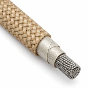
MGT Cable — Mica-Glass High Temperature Lead Wire 450°C / 538°C
A related cable option for a different application or duty profile.
View product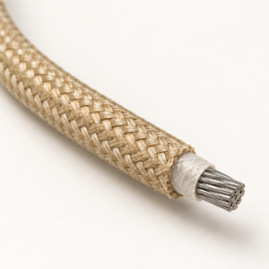
UL 5359 Mica-Glass Wire, 600V 200/450°C
A related cable option for a different application or duty profile.
View productRequest a cable recommendation and quotation
Send the required services, cable length, mechanical duty, environment, termination and quantity. Our team will review the application before quoting.
- Include the product name or SKU plus the required cable length and quantity.
- Attach a specification, drawing or data sheet when available.