

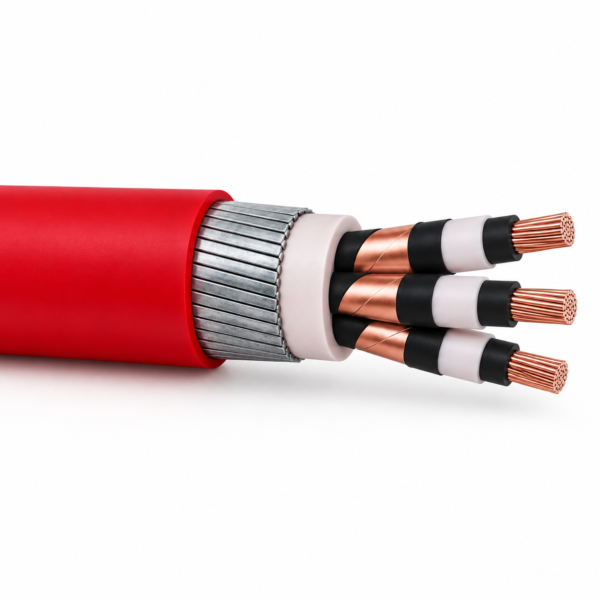
RG7OZR / RG7H1OZR Three-Core Armoured HEPR Cable
Three-core HEPR G7 insulated, flat-steel-wire-armoured PVC-sheathed power cable family. RG7OZR covers 1.8/3–3.6/6 kV without individual copper-tape screens; RG7H1OZR covers 6/10–18/30 kV with individually screened cores.
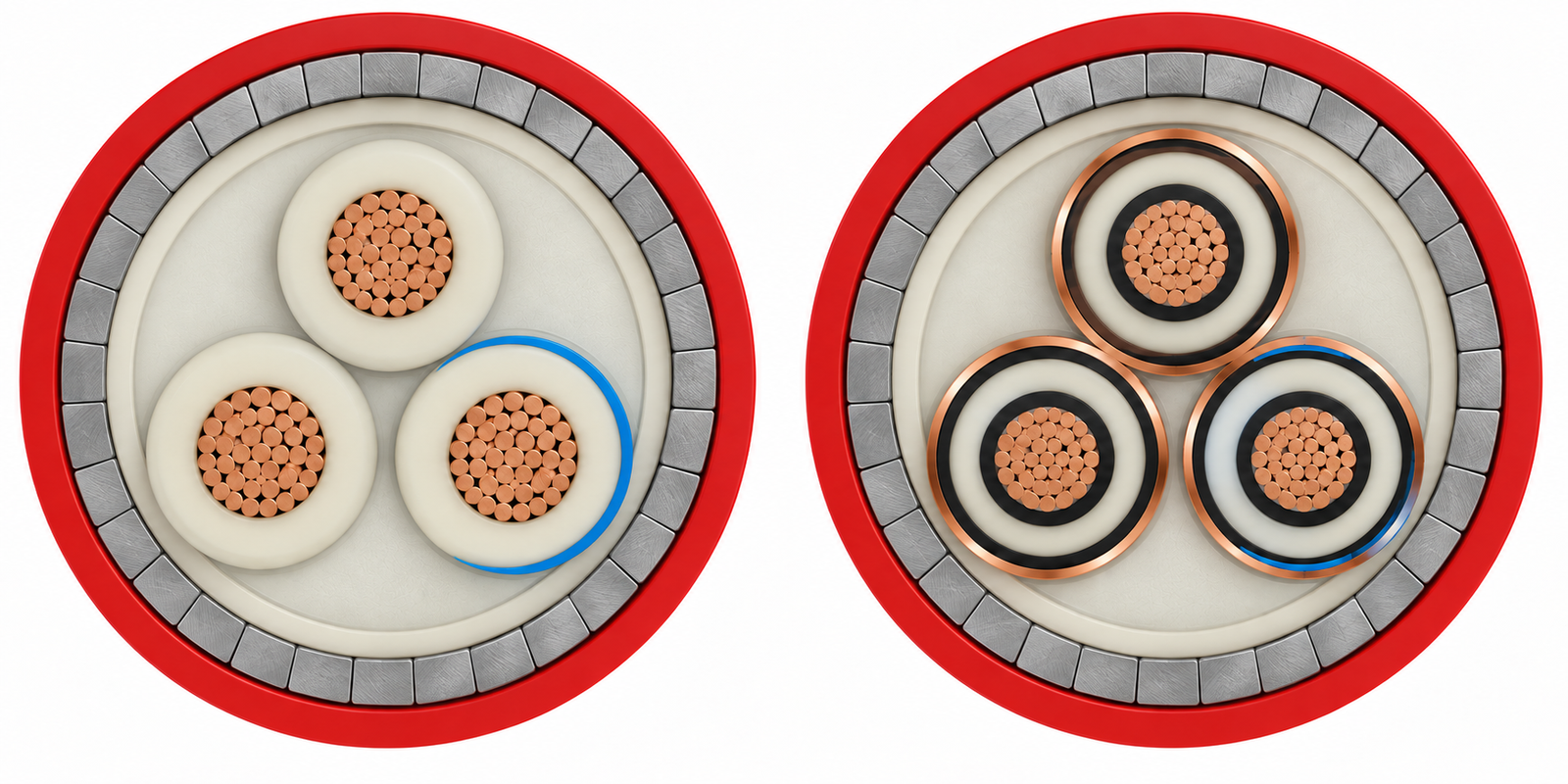
RG7OZR and RG7H1OZR are related three-core armoured HEPR-insulated power cables with a red PVC outer sheath. Their shared features are compact Class 2 plain-copper conductors, G7 HEPR insulation, a PVC inner sheath and galvanized flat steel wire armour. The electrical boundary between the two model names matters: the supplied source uses RG7OZR for U₀/U 1.8/3 and 3.6/6 kV without individual copper-tape core screens, while RG7H1OZR covers 6/10 through 18/30 kV with copper-tape-screened cores and extruded semiconductive layers.
Select the exact model and voltage before choosing a diameter or termination. The armour can serve a protective mechanical role, but it does not make the two screen constructions interchangeable. Confirm armour earthing, metallic-screen continuity, gland design and fault-current duty against the project diagram. Both source variants include extensive voltage-specific rows for size, insulation thickness, outer diameter, weight, air/buried current, resistance, reactance and capacitance.
Use the source guidance for fixed transformer-to-load transmission in air, ducts, open routes or compliant burial. If the route does not need this flat-steel-wire armour, compare the unarmoured RG7H1OR; consult the industrial cable range for further power designs.
Construction
Both designations are three-core, HEPR-insulated and PVC-sheathed with galvanized flat steel wire armour. The core-screen layer distinguishes the two source models.
| Layer | RG7OZR 1.8/3–3.6/6 kV | RG7H1OZR 6/10–18/30 kV |
|---|---|---|
| Conductor | Class 2 compact plain copper | Class 2 compact plain copper |
| Semiconductive screens | Not specified around individual cores | Extruded inner and cold-strippable outer layers |
| Insulation | G7 HEPR | G7 HEPR |
| Metallic core screen | No individual copper-tape screen; source assigns global-screen function to armour | Wrapped plain-copper tapes around cores |
| Core assembly | Phase bands/threads, extruded PVC inner sheath | Phase bands/threads, extruded PVC inner sheath |
| Armour | Galvanized flat steel wires with helical tape | Galvanized flat steel wires with helical tape |
| Outer sheath | Red Rz PVC | Red Rz PVC |
Applications
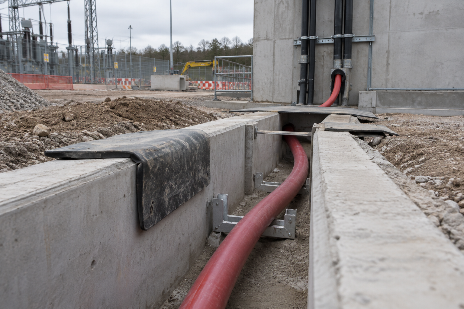
The source family serves fixed energy routes between transformer rooms and larger power users where flat steel wire armour is specified. It describes laying in air, pipe, open route and certain underground routes subject to CEI 11-17 Article 4.3.11. Check burial conditions, cable handling and sheath exposure against the design before choosing direct burial.
Specify RG7OZR for the source 1.8/3 or 3.6/6 kV unscreened-core variant; specify RG7H1OZR for the 6/10–18/30 kV individually copper-tape-screened variant. This difference controls termination and bonding details. The source recommends a 16 × OD bend and 60 N/mm² maximum pulling stress based on copper area. Confirm actual cable OD, pulling route and gland size from the chosen row.
For a three-core cable without flat steel wire armour, compare RG7H1OR.
When each phase must run as a separate cable rather than inside a three-core armoured assembly, compare the RG7H1R single-core HEPR insulated power cable, which keeps the G7 HEPR insulation and red PVC sheath with a copper-wire screen.
Specifications
| Selection property | Source range or value |
|---|---|
| Conductor | Class 2 compact stranded plain copper |
| HEPR insulation | G7, lead-free in supplied catalogue |
| Max continuous operating temperature | +90 °C |
| Minimum operating temperature | −15 °C without mechanical shocks |
| Max short-circuit conductor temperature | +250 °C |
| Minimum installation temperature | 0 °C |
| Recommended maximum pulling stress | 60 N/mm² of copper cross section |
| Model | Rated U₀/U | Max operating Uₘ from source tables | Screen construction |
|---|---|---|---|
| RG7OZR | 1.8/3 and 3.6/6 kV | 3.6 and 7.2 kV | Global armour screen; no individual copper-tape core screens |
| RG7H1OZR | 6/10, 8.7/15, 12/20 and 18/30 kV | 12, 17.5, 24 and 36 kV | Copper tapes around individual cores plus armour |
| Mechanical parameter | Source value |
|---|---|
| Recommended minimum bend | 16 × OD |
| Maximum recommended pulling stress | 60 N/mm² of copper conductor section |
| Minimum installation temperature | 0 °C |
RG7OZR 1.8/3 kV size and electrical data
| Model + conductor | Conductor Ø mm | Insulation mm | Max OD mm | Approx. kg/km | Air A | Buried A |
|---|---|---|---|---|---|---|
| RG7OZR 3 x 10 mm² 1.8/3 kV | 4.0 | 2.0 | 29.0 | 1370 | 81 | 89 |
| RG7OZR 3 x 16 mm² 1.8/3 kV | 4.8 | 2.0 | 31.0 | 1690 | 105 | 115 |
| RG7OZR 3 x 25 mm² 1.8/3 kV | 6.0 | 2.0 | 34.0 | 2100 | 138 | 148 |
| RG7OZR 3 x 35 mm² 1.8/3 kV | 7.0 | 2.0 | 36.5 | 2500 | 166 | 175 |
| RG7OZR 3 x 50 mm² 1.8/3 kV | 8.1 | 2.0 | 39.5 | 3035 | 200 | 208 |
| RG7OZR 3 x 70 mm² 1.8/3 kV | 9.7 | 2.0 | 43.0 | 3880 | 250 | 255 |
| RG7OZR 3 x 95 mm² 1.8/3 kV | 11.4 | 2.0 | 47.5 | 4900 | 305 | 303 |
| RG7OZR 3 x 120 mm² 1.8/3 kV | 12.9 | 2.0 | 51.5 | 5900 | 351 | 345 |
| RG7OZR 3 x 150 mm² 1.8/3 kV | 14.3 | 2.0 | 54.5 | 6850 | 398 | 385 |
| RG7OZR 3 x 185 mm² 1.8/3 kV | 16.0 | 2.0 | 58.5 | 8180 | 455 | 435 |
| RG7OZR 3 x 240 mm² 1.8/3 kV | 18.3 | 2.0 | 64.5 | 10300 | 540 | 505 |
| RG7OZR 3 x 300 mm² 1.8/3 kV | 21.0 | 2.0 | 77.0 | 12500 | 615 | 565 |
| RG7OZR 3 x 400 mm² 1.8/3 kV | 23.2 | 2.0 | 78.5 | 15500 | 715 | 645 |
| Model + conductor | Max DC Ω/km at 20°C | AC Ω/km at 90°C | Reactance Ω/km | Capacitance µF/km at 50 Hz |
|---|---|---|---|---|
| RG7OZR 3 x 10 mm² 1.8/3 kV | 1.83 | 2.34 | 0.11 | 0.19 |
| RG7OZR 3 x 16 mm² 1.8/3 kV | 1.15 | 1.47 | 0.10 | 0.23 |
| RG7OZR 3 x 25 mm² 1.8/3 kV | 0.727 | 0.927 | 0.097 | 0.27 |
| RG7OZR 3 x 35 mm² 1.8/3 kV | 0.524 | 0.669 | 0.093 | 0.30 |
| RG7OZR 3 x 50 mm² 1.8/3 kV | 0.387 | 0.494 | 0.088 | 0.34 |
| RG7OZR 3 x 70 mm² 1.8/3 kV | 0.268 | 0.342 | 0.084 | 0.40 |
| RG7OZR 3 x 95 mm² 1.8/3 kV | 0.193 | 0.247 | 0.081 | 0.45 |
| RG7OZR 3 x 120 mm² 1.8/3 kV | 0.153 | 0.197 | 0.079 | 0.50 |
| RG7OZR 3 x 150 mm² 1.8/3 kV | 0.124 | 0.159 | 0.077 | 0.55 |
| RG7OZR 3 x 185 mm² 1.8/3 kV | 0.0991 | 0.129 | 0.076 | 0.60 |
| RG7OZR 3 x 240 mm² 1.8/3 kV | 0.0754 | 0.0990 | 0.074 | 0.68 |
| RG7OZR 3 x 300 mm² 1.8/3 kV | 0.0601 | 0.0807 | 0.072 | 0.75 |
| RG7OZR 3 x 400 mm² 1.8/3 kV | 0.0470 | 0.0651 | 0.071 | 0.83 |
Reference values are indicative. Confirm nominal dimensions and approximate mass on the project drawing; buried-current figures assume ground thermal resistivity of 100 °C cm/W.
RG7OZR 3.6/6 kV size and electrical data
| Model + conductor | Conductor Ø mm | Insulation mm | Max OD mm | Approx. kg/km | Air A | Buried A |
|---|---|---|---|---|---|---|
| RG7OZR 3 x 10 mm² 3.6/6 kV | 4.0 | 3.0 | 33.5 | 1695 | 78 | 85 |
| RG7OZR 3 x 16 mm² 3.6/6 kV | 4.8 | 3.0 | 36.5 | 1970 | 103 | 108 |
| RG7OZR 3 x 25 mm² 3.6/6 kV | 6.0 | 3.0 | 39.0 | 2580 | 130 | 138 |
| RG7OZR 3 x 35 mm² 3.6/6 kV | 7.0 | 3.0 | 41.5 | 3040 | 160 | 165 |
| RG7OZR 3 x 50 mm² 3.6/6 kV | 8.1 | 3.0 | 44.0 | 3500 | 190 | 195 |
| RG7OZR 3 x 70 mm² 3.6/6 kV | 9.7 | 3.0 | 48.5 | 4400 | 235 | 240 |
| RG7OZR 3 x 95 mm² 3.6/6 kV | 11.4 | 3.0 | 52.5 | 5555 | 285 | 285 |
| RG7OZR 3 x 120 mm² 3.6/6 kV | 12.9 | 3.0 | 56.5 | 6545 | 330 | 330 |
| RG7OZR 3 x 150 mm² 3.6/6 kV | 14.3 | 3.0 | 59.5 | 7450 | 373 | 365 |
| RG7OZR 3 x 185 mm² 3.6/6 kV | 16.0 | 3.0 | 64.5 | 8900 | 430 | 415 |
| RG7OZR 3 x 240 mm² 3.6/6 kV | 18.3 | 3.0 | 69.5 | 11000 | 503 | 480 |
| RG7OZR 3 x 300 mm² 3.6/6 kV | 21.0 | 3.0 | 76.5 | 13250 | 577 | 540 |
| RG7OZR 3 x 400 mm² 3.6/6 kV | 23.2 | 3.0 | 83.5 | 16200 | 670 | 620 |
| Model + conductor | Max DC Ω/km at 20°C | AC Ω/km at 90°C | Reactance Ω/km | Capacitance µF/km at 50 Hz |
|---|---|---|---|---|
| RG7OZR 3 x 10 mm² 3.6/6 kV | 1.83 | 2.34 | 0.12 | 0.15 |
| RG7OZR 3 x 16 mm² 3.6/6 kV | 1.15 | 1.47 | 0.12 | 0.17 |
| RG7OZR 3 x 25 mm² 3.6/6 kV | 0.727 | 0.927 | 0.11 | 0.20 |
| RG7OZR 3 x 35 mm² 3.6/6 kV | 0.524 | 0.669 | 0.10 | 0.23 |
| RG7OZR 3 x 50 mm² 3.6/6 kV | 0.387 | 0.494 | 0.097 | 0.26 |
| RG7OZR 3 x 70 mm² 3.6/6 kV | 0.268 | 0.342 | 0.092 | 0.30 |
| RG7OZR 3 x 95 mm² 3.6/6 kV | 0.193 | 0.247 | 0.089 | 0.33 |
| RG7OZR 3 x 120 mm² 3.6/6 kV | 0.153 | 0.197 | 0.086 | 0.37 |
| RG7OZR 3 x 150 mm² 3.6/6 kV | 0.124 | 0.159 | 0.084 | 0.40 |
| RG7OZR 3 x 185 mm² 3.6/6 kV | 0.0991 | 0.129 | 0.082 | 0.44 |
| RG7OZR 3 x 240 mm² 3.6/6 kV | 0.0754 | 0.0990 | 0.079 | 0.49 |
| RG7OZR 3 x 300 mm² 3.6/6 kV | 0.0601 | 0.0807 | 0.077 | 0.54 |
| RG7OZR 3 x 400 mm² 3.6/6 kV | 0.0470 | 0.0651 | 0.075 | 0.60 |
Reference values are indicative. Confirm nominal dimensions and approximate mass on the project drawing; buried-current figures assume ground thermal resistivity of 100 °C cm/W.
RG7H1OZR 6/10 kV size and electrical data
| Model + conductor | Conductor Ø mm | Insulation mm | Max OD mm | Approx. kg/km | Air A | Buried A |
|---|---|---|---|---|---|---|
| RG7H1OZR 3 x 10 mm² 6/10 kV | 4.0 | 3.4 | 41.5 | 2665 | 71 | 77 |
| RG7H1OZR 3 x 16 mm² 6/10 kV | 4.8 | 3.4 | 44.0 | 3065 | 105 | 111 |
| RG7H1OZR 3 x 25 mm² 6/10 kV | 6.0 | 3.4 | 47.3 | 3555 | 143 | 145 |
| RG7H1OZR 3 x 35 mm² 6/10 kV | 7.0 | 3.4 | 50.0 | 4080 | 170 | 172 |
| RG7H1OZR 3 x 50 mm² 6/10 kV | 8.1 | 3.4 | 53.0 | 4735 | 205 | 203 |
| RG7H1OZR 3 x 70 mm² 6/10 kV | 9.7 | 3.4 | 57.4 | 5685 | 253 | 250 |
| RG7H1OZR 3 x 95 mm² 6/10 kV | 11.4 | 3.4 | 60.3 | 6880 | 305 | 296 |
| RG7H1OZR 3 x 120 mm² 6/10 kV | 12.9 | 3.4 | 65.3 | 8135 | 353 | 337 |
| RG7H1OZR 3 x 150 mm² 6/10 kV | 14.3 | 3.4 | 68.5 | 9360 | 393 | 375 |
| RG7H1OZR 3 x 185 mm² 6/10 kV | 16.0 | 3.4 | 72.5 | 10920 | 447 | 425 |
| RG7H1OZR 3 x 240 mm² 6/10 kV | 18.3 | 3.4 | 78.6 | 13480 | 525 | 490 |
| RG7H1OZR 3 x 300 mm² 6/10 kV | 21.0 | 3.4 | 84.6 | 16020 | 595 | 550 |
| RG7H1OZR 3 x 400 mm² 6/10 kV | 23.2 | 3.4 | 90.6 | 16865 | 677 | 620 |
| Model + conductor | Max DC Ω/km at 20°C | AC Ω/km at 90°C | Reactance Ω/km | Capacitance µF/km at 50 Hz |
|---|---|---|---|---|
| RG7H1OZR 3 x 10 mm² 6/10 kV | 1.83 | 2.34 | 0.14 | 0.16 |
| RG7H1OZR 3 x 16 mm² 6/10 kV | 1.15 | 1.47 | 0.13 | 0.18 |
| RG7H1OZR 3 x 25 mm² 6/10 kV | 0.727 | 0.927 | 0.12 | 0.21 |
| RG7H1OZR 3 x 35 mm² 6/10 kV | 0.524 | 0.669 | 0.11 | 0.23 |
| RG7H1OZR 3 x 50 mm² 6/10 kV | 0.387 | 0.494 | 0.11 | 0.26 |
| RG7H1OZR 3 x 70 mm² 6/10 kV | 0.268 | 0.342 | 0.10 | 0.29 |
| RG7H1OZR 3 x 95 mm² 6/10 kV | 0.193 | 0.247 | 0.097 | 0.32 |
| RG7H1OZR 3 x 120 mm² 6/10 kV | 0.153 | 0.197 | 0.094 | 0.36 |
| RG7H1OZR 3 x 150 mm² 6/10 kV | 0.124 | 0.159 | 0.091 | 0.38 |
| RG7H1OZR 3 x 185 mm² 6/10 kV | 0.0991 | 0.129 | 0.088 | 0.42 |
| RG7H1OZR 3 x 240 mm² 6/10 kV | 0.0754 | 0.0990 | 0.085 | 0.47 |
| RG7H1OZR 3 x 300 mm² 6/10 kV | 0.0601 | 0.0807 | 0.084 | 0.52 |
| RG7H1OZR 3 x 400 mm² 6/10 kV | 0.0470 | 0.0651 | 0.082 | 0.57 |
Reference values are indicative. Confirm nominal dimensions and approximate mass on the project drawing; buried-current figures assume ground thermal resistivity of 100 °C cm/W.
RG7H1OZR 8.7/15 kV size and electrical data
| Model + conductor | Conductor Ø mm | Insulation mm | Max OD mm | Approx. kg/km | Air A | Buried A |
|---|---|---|---|---|---|---|
| RG7H1OZR 3 x 16 mm² 8.7/15 kV | 4.8 | 4.5 | 49.5 | 3700 | 95 | 98 |
| RG7H1OZR 3 x 25 mm² 8.7/15 kV | 6.0 | 4.5 | 52.5 | 4295 | 142 | 140 |
| RG7H1OZR 3 x 35 mm² 8.7/15 kV | 7.0 | 4.5 | 55.0 | 4805 | 171 | 168 |
| RG7H1OZR 3 x 50 mm² 8.7/15 kV | 8.1 | 4.5 | 57.3 | 5500 | 205 | 200 |
| RG7H1OZR 3 x 70 mm² 8.7/15 kV | 9.7 | 4.5 | 61.5 | 6559 | 252 | 245 |
| RG7H1OZR 3 x 95 mm² 8.7/15 kV | 11.4 | 4.5 | 65.5 | 7785 | 303 | 290 |
| RG7H1OZR 3 x 120 mm² 8.7/15 kV | 12.9 | 4.5 | 69.5 | 9080 | 347 | 327 |
| RG7H1OZR 3 x 150 mm² 8.7/15 kV | 14.3 | 4.5 | 72.5 | 10355 | 390 | 365 |
| RG7H1OZR 3 x 185 mm² 8.7/15 kV | 16.0 | 4.5 | 76.5 | 11050 | 446 | 413 |
| RG7H1OZR 3 x 240 mm² 8.7/15 kV | 18.3 | 4.5 | 82.5 | 13300 | 520 | 476 |
| RG7H1OZR 3 x 300 mm² 8.7/15 kV | 21.0 | 4.5 | 88.6 | 15850 | 595 | 535 |
| Model + conductor | Max DC Ω/km at 20°C | AC Ω/km at 90°C | Reactance Ω/km | Capacitance µF/km at 50 Hz |
|---|---|---|---|---|
| RG7H1OZR 3 x 16 mm² 8.7/15 kV | 1.15 | 1.47 | 0.14 | 0.15 |
| RG7H1OZR 3 x 25 mm² 8.7/15 kV | 0.727 | 0.927 | 0.13 | 0.18 |
| RG7H1OZR 3 x 35 mm² 8.7/15 kV | 0.524 | 0.669 | 0.12 | 0.19 |
| RG7H1OZR 3 x 50 mm² 8.7/15 kV | 0.387 | 0.494 | 0.12 | 0.21 |
| RG7H1OZR 3 x 70 mm² 8.7/15 kV | 0.268 | 0.342 | 0.11 | 0.24 |
| RG7H1OZR 3 x 95 mm² 8.7/15 kV | 0.193 | 0.247 | 0.10 | 0.26 |
| RG7H1OZR 3 x 120 mm² 8.7/15 kV | 0.153 | 0.197 | 0.10 | 0.29 |
| RG7H1OZR 3 x 150 mm² 8.7/15 kV | 0.124 | 0.159 | 0.097 | 0.31 |
| RG7H1OZR 3 x 185 mm² 8.7/15 kV | 0.0991 | 0.129 | 0.094 | 0.34 |
| RG7H1OZR 3 x 240 mm² 8.7/15 kV | 0.0754 | 0.0990 | 0.090 | 0.37 |
| RG7H1OZR 3 x 300 mm² 8.7/15 kV | 0.0601 | 0.0807 | 0.088 | 0.42 |
Reference values are indicative. Confirm nominal dimensions and approximate mass on the project drawing; buried-current figures assume ground thermal resistivity of 100 °C cm/W.
RG7H1OZR 12/20 kV size and electrical data
| Model + conductor | Conductor Ø mm | Insulation mm | Max OD mm | Approx. kg/km | Air A | Buried A |
|---|---|---|---|---|---|---|
| RG7H1OZR 3 x 35 mm² 12/20 kV | 7.0 | 5.5 | 59.5 | 4975 | 173 | 177 |
| RG7H1OZR 3 x 50 mm² 12/20 kV | 8.1 | 5.5 | 62.5 | 6175 | 203 | 208 |
| RG7H1OZR 3 x 70 mm² 12/20 kV | 9.7 | 5.5 | 67.0 | 7305 | 251 | 255 |
| RG7H1OZR 3 x 95 mm² 12/20 kV | 11.4 | 5.5 | 70.5 | 8540 | 303 | 301 |
| RG7H1OZR 3 x 120 mm² 12/20 kV | 12.9 | 5.5 | 75.0 | 9925 | 348 | 342 |
| RG7H1OZR 3 x 150 mm² 12/20 kV | 14.3 | 5.5 | 78.0 | 11270 | 393 | 381 |
| RG7H1OZR 3 x 185 mm² 12/20 kV | 16.0 | 5.5 | 81.5 | 12935 | 448 | 431 |
| RG7H1OZR 3 x 240 mm² 12/20 kV | 18.3 | 5.5 | 88.0 | 15625 | 520 | 495 |
| RG7H1OZR 3 x 300 mm² 12/20 kV | 21.0 | 5.5 | 94.0 | 18300 | 595 | 555 |
| Model + conductor | Max DC Ω/km at 20°C | AC Ω/km at 90°C | Reactance Ω/km | Capacitance µF/km at 50 Hz |
|---|---|---|---|---|
| RG7H1OZR 3 x 35 mm² 12/20 kV | 0.524 | 0.669 | 0.13 | 0.17 |
| RG7H1OZR 3 x 50 mm² 12/20 kV | 0.387 | 0.494 | 0.12 | 0.18 |
| RG7H1OZR 3 x 70 mm² 12/20 kV | 0.268 | 0.342 | 0.11 | 0.21 |
| RG7H1OZR 3 x 95 mm² 12/20 kV | 0.193 | 0.247 | 0.10 | 0.23 |
| RG7H1OZR 3 x 120 mm² 12/20 kV | 0.153 | 0.197 | 0.10 | 0.25 |
| RG7H1OZR 3 x 150 mm² 12/20 kV | 0.124 | 0.159 | 0.10 | 0.27 |
| RG7H1OZR 3 x 185 mm² 12/20 kV | 0.0991 | 0.129 | 0.098 | 0.29 |
| RG7H1OZR 3 x 240 mm² 12/20 kV | 0.0754 | 0.0990 | 0.094 | 0.32 |
| RG7H1OZR 3 x 300 mm² 12/20 kV | 0.0601 | 0.0807 | 0.092 | 0.35 |
Reference values are indicative. Confirm nominal dimensions and approximate mass on the project drawing; buried-current figures assume ground thermal resistivity of 100 °C cm/W.
RG7H1OZR 18/30 kV size and electrical data
| Model + conductor | Conductor Ø mm | Insulation mm | Max OD mm | Approx. kg/km | Air A | Buried A |
|---|---|---|---|---|---|---|
| RG7H1OZR 3 x 50 mm² 18/30 kV | 8.1 | 8.0 | 76.0 | 8450 | 202 | 205 |
| RG7H1OZR 3 x 70 mm² 18/30 kV | 9.7 | 8.0 | 79.5 | 9610 | 250 | 252 |
| RG7H1OZR 3 x 95 mm² 18/30 kV | 11.4 | 8.0 | 83.5 | 10980 | 302 | 300 |
| RG7H1OZR 3 x 120 mm² 18/30 kV | 12.9 | 8.0 | 88.0 | 12680 | 345 | 340 |
| RG7H1OZR 3 x 150 mm² 18/30 kV | 14.3 | 8.0 | 90.0 | 14130 | 390 | 378 |
| RG7H1OZR 3 x 185 mm² 18/30 kV | 16.0 | 8.0 | 95.0 | 15645 | 445 | 428 |
| Model + conductor | Max DC Ω/km at 20°C | AC Ω/km at 90°C | Reactance Ω/km | Capacitance µF/km at 50 Hz |
|---|---|---|---|---|
| RG7H1OZR 3 x 50 mm² 18/30 kV | 0.387 | 0.494 | 0.13 | 0.15 |
| RG7H1OZR 3 x 70 mm² 18/30 kV | 0.268 | 0.342 | 0.13 | 0.16 |
| RG7H1OZR 3 x 95 mm² 18/30 kV | 0.193 | 0.247 | 0.12 | 0.18 |
| RG7H1OZR 3 x 120 mm² 18/30 kV | 0.153 | 0.197 | 0.12 | 0.19 |
| RG7H1OZR 3 x 150 mm² 18/30 kV | 0.124 | 0.159 | 0.11 | 0.20 |
| RG7H1OZR 3 x 185 mm² 18/30 kV | 0.0991 | 0.129 | 0.11 | 0.22 |
Reference values are indicative. Confirm nominal dimensions and approximate mass on the project drawing; buried-current figures assume ground thermal resistivity of 100 °C cm/W.
Standards
Reference standards for this armoured family include CEI 20-13 and IEC 60502 as structure/electrical/mechanical references; CEI 20-16 for partial-discharge measurement; EN 60332-1-2 for flame propagation; EN 60332-3-24 for fire propagation; and EN 50267-2-1 for corrosive gas or halogen measurement. Its burial guidance refers to CEI 11-17 Article 4.3.11. Specify project editions and acceptance tests with the exact RG7OZR or RG7H1OZR construction.
The final quotation and documentation should identify the ordered voltage, core-screen construction and armour earthing arrangement.
Related cable options
Compare these cable options by service combination, movement, load, voltage and transmission requirement.
RG7H1R Single-Core HEPR Insulated Power Cable
A related cable option for a different application or duty profile.
View product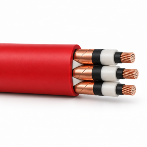
RG7H1OR Three-Core HEPR Insulated MV Cable
A related cable option for a different application or duty profile.
View productRequest a cable recommendation and quotation
Send the required services, cable length, mechanical duty, environment, termination and quantity. Our team will review the application before quoting.
- Include the product name or SKU plus the required cable length and quantity.
- Attach a specification, drawing or data sheet when available.