


2XSLCYK-J 0.6/1 kV XLPE VFD Motor Cable
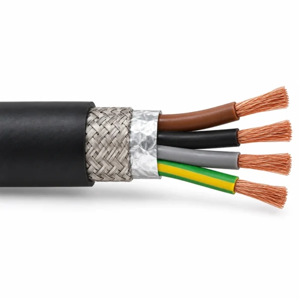
2XSLCYK-J 0.6/1 kV VFD motor cable with Class 5 copper conductors, XLPE insulation, aluminium/PETP foil and tinned copper braid screening, and a black PVC sheath. Available in 4G and 3+3 configurations from 1.5 to 300 mm² for fixed routes and occasional movement under medium mechanical stress.
- Rated voltage: 0.6/1 kV; test voltage: 4 kV.
- Flexible class 5 bare copper conductors.
- XLPE insulation; maximum operating conductor temperature 90 °C.
- Aluminium/polyester foil and tinned-copper braid screens.
- Black PVC sheath; 4G and 3+3 size tables.
- Fixed routes and occasional movement; diameter-dependent bend limits.
Send the full core configuration, route length, drive rating and installation conditions for a technical quotation.
2XSLCYK-J XLPE cable for inverter-fed motors
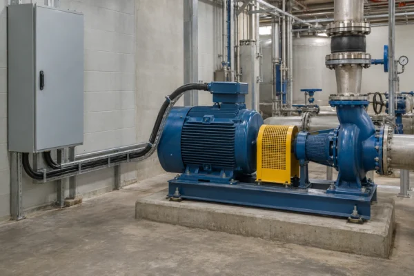
2XSLCYK-J is a 0.6/1 kV VFD motor cable with XLPE insulation, an aluminium/PETP foil screen, tinned copper braid and a black PVC sheath. It connects a frequency converter to a motor where the power circuit requires electromagnetic screening. Typical installations include industrial pumps, fans, conveyors and air-conditioning equipment.
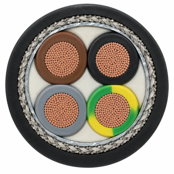
This family offers two earth-conductor arrangements across a 1.5–300 mm² phase-conductor range. The 4G version combines three phase conductors with one full-size protective-earth conductor. The 3+3 version places three smaller green/yellow earth conductors in the spaces between the phase cores. Select the arrangement required by the drive and motor installation, then use the matching dimension table to check gland space, routing clearance and cable weight.
Flexible Class 5 copper supports handling and occasional movement under medium mechanical stress. XLPE permits a maximum conductor temperature of 90 °C; the stated fixed-laying temperature range is −40 to +70 °C. These are different limits: the conductor rating does not replace the ambient-temperature requirement or establish a current rating by itself.
The foil-and-braid screen forms part of the complete EMC installation, including its terminations and earthing. For selection alongside other industrial cables, specify the complete model and core configuration, route length, installation method and operating conditions. The tables below separate the electrical limits, bending requirements and both size families so the quotation can follow the required construction.
2XSLCYK-J construction
The XLPE-insulated cores sit within an overall foil-and-braid screen beneath the black PVC outer sheath. Both 4G and 3+3 configurations use the same principal insulation and screening materials.
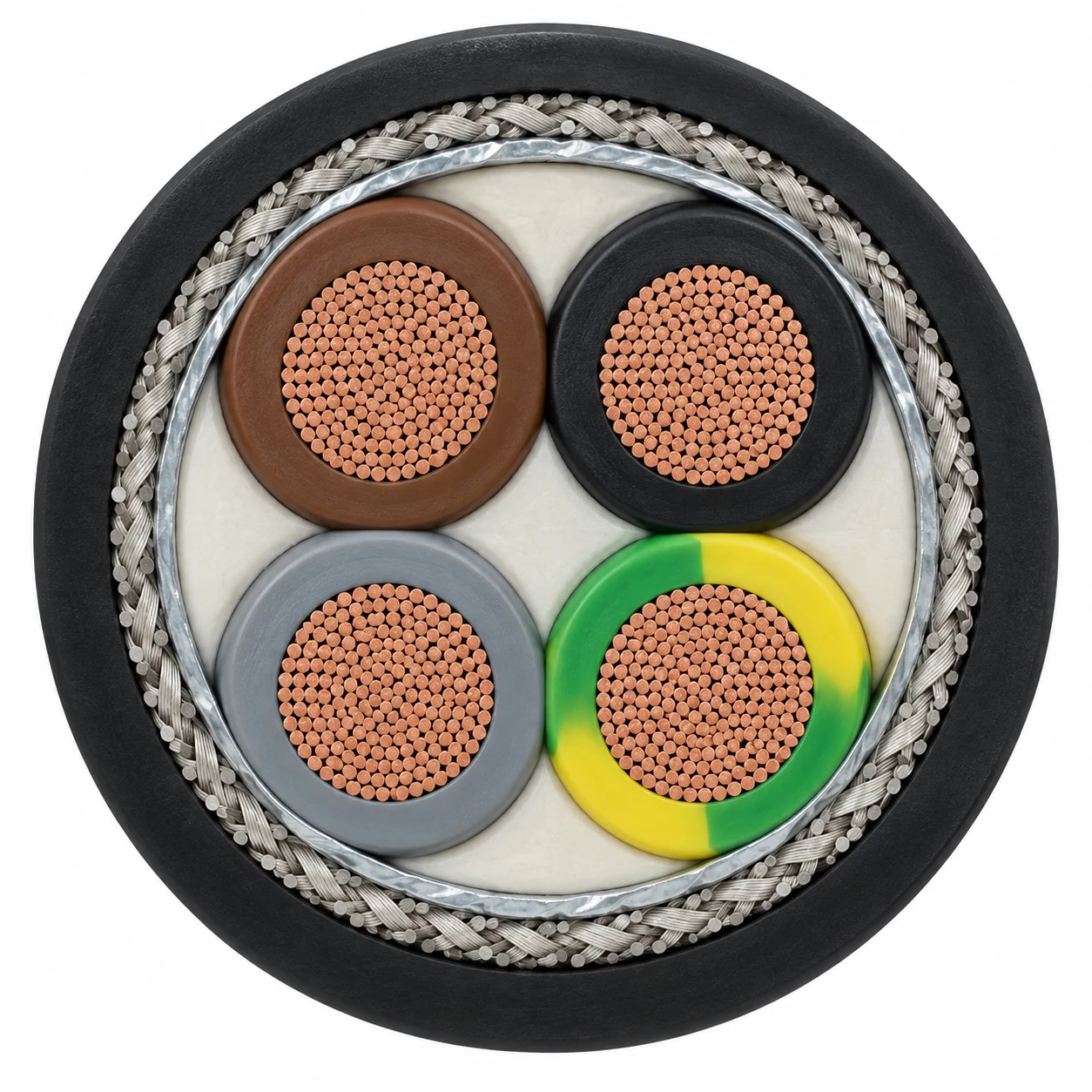
| Conductor | Class 5 flexible bare copper, with IEC 60228 and DIN VDE 0295 conductor references. |
|---|---|
| Insulation | Special cross-linked polyethylene (XLPE) compound. |
| First screen | Aluminium tape with PETP polyester foil. |
| Second screen | Overall tinned copper braid. |
| Outer sheath | Special PVC compound, black. |
| 4G core arrangement | Three phase cores and one full-size protective-earth core. |
| 3+3 core arrangement | Three phase cores and three reduced protective-earth cores distributed in the interstices. |
| Core identification | Brown, black and grey phase cores; green/yellow protective-earth cores. |
The copper braid is an electromagnetic screen. The construction contains no steel armour or separate reinforcement layer. For 3+3 orders, state both the phase and earth cross-sections; the phase size alone does not identify the complete configuration.
VFD-to-motor applications
2XSLCYK-J supplies motors from frequency converters in installations with medium mechanical stress. Suitable routes include fixed wiring and occasional movement in dry, damp or wet environments, including outdoor applications.
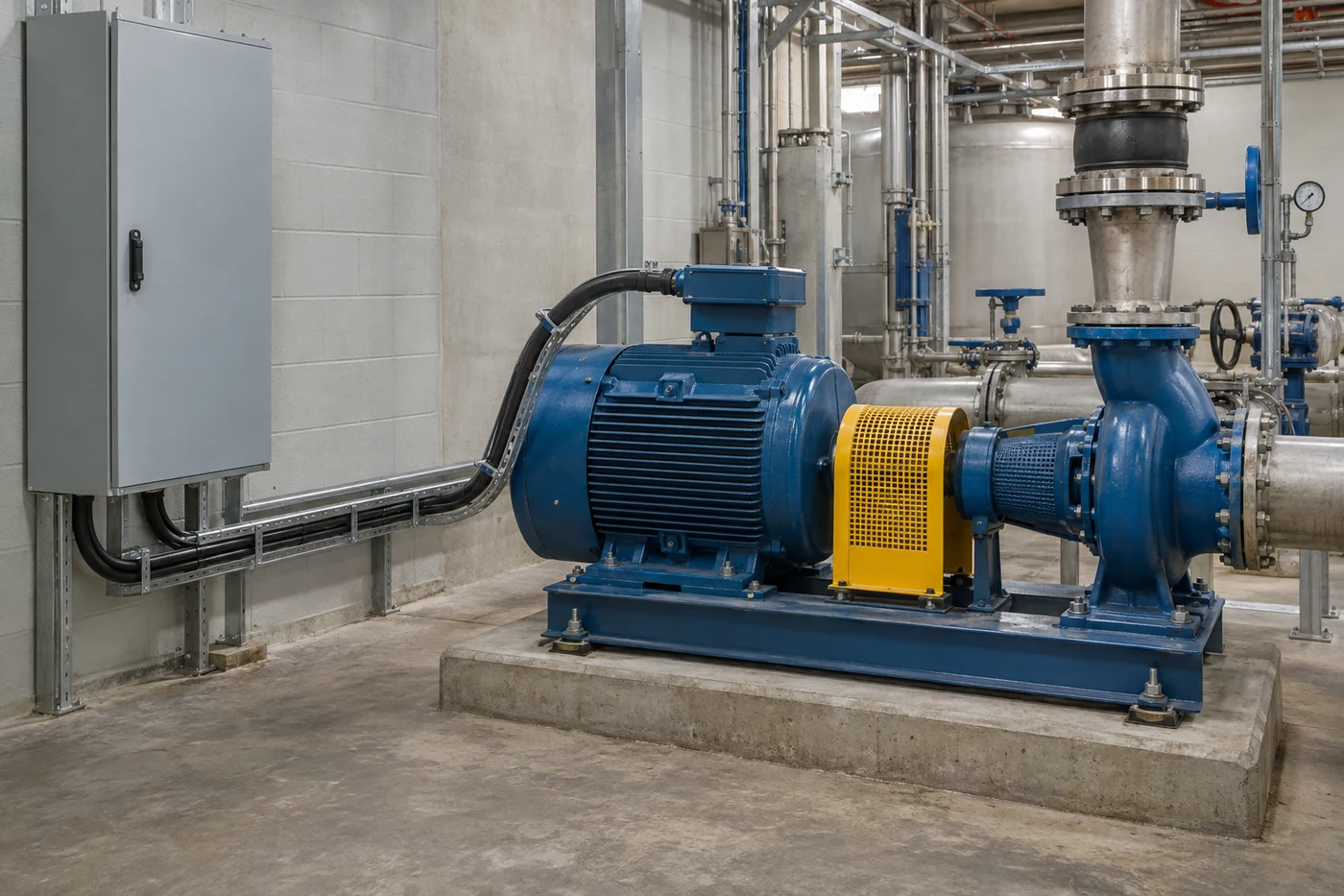
- Pumps and ventilation: screened motor connections for variable-speed industrial pumps and fans.
- Conveyors and process equipment: inverter-fed motor power routes through machinery and production areas.
- Air-conditioning systems: VFD connections where motor speed is adjusted to operating demand.
Match the cable to the complete drive installation
Choose the 4G or 3+3 earth arrangement specified for the equipment. Review the nominal diameter against glands and entry space, and apply the relevant fixed or flexible bend radius throughout the route. The fixed-laying ambient range and conductor-temperature limit must each suit the installation.
Plan large-area, circumferential screen connections at both ends in line with the drive manufacturer's EMC instructions. Our cable shielding guide explains how braid construction differs from a spiral screen.
For continuous drag-chain travel, repeated torsion, reeling, direct burial or submerged service, provide the duty and environment for a separate construction review. Occasional flexibility alone does not establish suitability for those applications.
Choosing between related motor cables
This XLPE-insulated construction has a 90 °C conductor limit. The PE-insulated 2YSLCYK-J and 2YSLCYK-JB constructions shown in the related products have different thermal and dimensional data. Choose the required insulation and earth arrangement before comparing sizes.
2XSLCYK-J electrical and mechanical specifications
The following data apply to the 0.6/1 kV XLPE-insulated, foil-and-braid-screened PVC construction. Temperature limits distinguish the cable's fixed-laying conditions from the temperature of the conductor.
| Rated voltage U₀/U | 0.6/1 kV |
|---|---|
| Test voltage | 4 kV |
| Maximum AC operating voltage | 0.7 kV conductor/earth; 1.2 kV conductor/conductor for three-phase AC. |
| Maximum DC operating voltage | 0.9 kV conductor/earth; 1.8 kV conductor/conductor. |
| Fixed-laying temperature range | −40 to +70 °C |
| Maximum operating conductor temperature | 90 °C |
| Maximum short-circuit conductor temperature | 250 °C |
| Minimum insulation resistance | 200 MΩ·km |
| Maximum coupling resistance | 250 Ω/km, depending on cross-section. |
| Core-to-core capacitance, 4-core version | 70–250 nF/km, depending on cross-section. |
| Core-to-screen capacitance, 4-core version | 110–410 nF/km, depending on cross-section. |
Capacitance values above refer to the four-conductor version. Current-carrying capacity must be selected for the loaded conductors, ambient conditions and installation method; a conductor-temperature limit is not an ampere rating.
Minimum bending radius
D is the finished cable's overall diameter. Values below are radii, not bending diameters; select the row for the actual cable diameter and the installation condition.
| Overall diameter D (mm) | Fixed installation radius | Flexible application radius |
|---|---|---|
| D ≤ 12 | 5 × D | 10 × D |
| 12 < D ≤ 20 | 7.5 × D | 15 × D |
| D > 20 | 10 × D | 20 × D |
4G dimensions and cable weight
Each 4G configuration contains three phase conductors and one green/yellow protective-earth conductor of the same cross-section. Cross-sections are in mm². All rows are rated 0.6/1 kV.
| Model + configuration (mm²) | Nominal overall diameter (mm) | Nominal cable weight (kg/km) |
|---|---|---|
| 2XSLCYK-J 4G1.5 | 11.3 | 230 |
| 2XSLCYK-J 4G2.5 | 12.4 | 300 |
| 2XSLCYK-J 4G4 | 13.6 | 485 |
| 2XSLCYK-J 4G6 | 14.8 | 630 |
| 2XSLCYK-J 4G10 | 17.5 | 860 |
| 2XSLCYK-J 4G16 | 20.2 | 1 290 |
| 2XSLCYK-J 4G25 | 24.8 | 1 860 |
| 2XSLCYK-J 4G35 | 27.4 | 2 610 |
| 2XSLCYK-J 4G50 | 32 | 2 950 |
| 2XSLCYK-J 4G70 | 37.1 | 3 950 |
| 2XSLCYK-J 4G95 | 41.6 | 5 300 |
| 2XSLCYK-J 4G120 | 45.2 | 6 600 |
| 2XSLCYK-J 4G150 | 52 | 7 040 |
| 2XSLCYK-J 4G185 | 58.1 | 8 380 |
| 2XSLCYK-J 4G240 | 66.1 | 11 300 |
| 2XSLCYK-J 4G300 | 71.5 | 13 800 |
3+3 dimensions and cable weight
The notation 3 × A + 3 × B means three phase conductors of A mm² and three green/yellow earth conductors of B mm². All rows are rated 0.6/1 kV; the reduced earth conductors are distributed between the phase cores.
| Model + configuration (mm²) | Nominal overall diameter (mm) | Nominal cable weight (kg/km) |
|---|---|---|
| 2XSLCYK-J 3 × 1.5 + 3 × 0.25 | 12 | 234 |
| 2XSLCYK-J 3 × 2.5 + 3 × 0.5 | 13 | 282 |
| 2XSLCYK-J 3 × 4 + 3 × 0.75 | 14 | 447 |
| 2XSLCYK-J 3 × 6 + 3 × 1 | 16 | 575 |
| 2XSLCYK-J 3 × 10 + 3 × 1.5 | 18 | 650 |
| 2XSLCYK-J 3 × 16 + 3 × 2.5 | 20 | 846 |
| 2XSLCYK-J 3 × 25 + 3 × 4 | 24 | 1 325 |
| 2XSLCYK-J 3 × 35 + 3 × 6 | 26 | 1 840 |
| 2XSLCYK-J 3 × 50 + 3 × 10 | 30 | 2 718 |
| 2XSLCYK-J 3 × 70 + 3 × 10 | 34 | 3 470 |
| 2XSLCYK-J 3 × 95 + 3 × 16 | 37 | 4 540 |
| 2XSLCYK-J 3 × 120 + 3 × 16 | 42 | 5 865 |
| 2XSLCYK-J 3 × 150 + 3 × 25 | 46 | 6 490 |
| 2XSLCYK-J 3 × 185 + 3 × 35 | 51 | 8 595 |
| 2XSLCYK-J 3 × 240 + 3 × 50 | 59 | 11 720 |
| 2XSLCYK-J 3 × 300 + 3 × 50 | 65 | 13 380 |
Dimensions and weights are nominal and may vary with manufacturing tolerances. Use the selected configuration when confirming cable glands, supports, installation space and the final order drawing.
2XSLCYK-J standards and test references
The references below identify the conductor, core identification, EMC, flame and environmental requirements associated with this construction.
| Technical subject | Reference |
|---|---|
| Flexible conductors | IEC 60228; DIN VDE 0295 |
| Core identification | DIN VDE 0293-308; HD 308 S2 |
| Electromagnetic compatibility | EN 55011; DIN VDE 0875 part 1 |
| Single-cable flame test | IEC 60332-1-2; EN 50265-2-1; DIN VDE 0482 part 265-2-1 |
| Fire testing and classification references | EN 50399; EN 13501-6; CEI UNEL 35016 |
| Construction products reference | EN 50575 |
IEC 60228 — Conductors of insulated cables provides the conductor reference used for the Class 5 construction. Include any project-specific fire classification and inspection documentation requirements with the selected size when requesting a quotation.
Related cable options
Compare these cable options by service combination, movement, load, voltage and transmission requirement.

2YSLCYK-J 0.6/1 kV Single-PE VFD Motor Cable
A related cable option for a different application or duty profile.
View product
2YSLCYK-JB 0.6/1 kV Symmetrical VFD Cable
A related cable option for a different application or duty profile.
View product
2YSLCY-JB Servo Motor Cable
A related cable option for a different application or duty profile.
View productRequest a cable recommendation and quotation
Send the required services, cable length, mechanical duty, environment, termination and quantity. Our team will review the application before quoting.
- Include the product name or SKU plus the required cable length and quantity.
- Attach a specification, drawing or data sheet when available.