


2YSLCYK-JB 0.6/1 kV Symmetrical VFD Cable
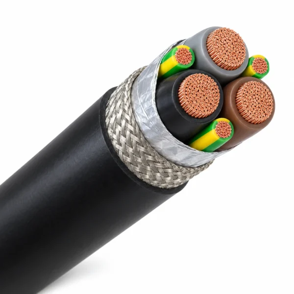
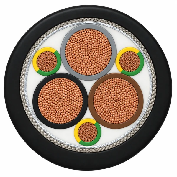
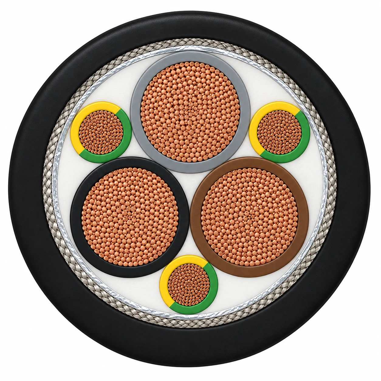
2YSLCYK-JB is a 0.6/1 kV double-screened VFD motor cable. The selected 3+3 version places three smaller green/yellow protective-earth cores symmetrically between three PE-insulated phase cores.
- Fine-stranded bare copper conductors, IEC 60228 class 5.
- Aluminium-coated foil and tinned-copper braid screens.
- Black PVC sheath for indoor and outdoor drive connections.
- 15 reference configurations from 3 X 1.5 + 3 G 0.25 to 3 X 240 + 3 G 50 mm².
- Bending radius: 4 × D fixed; 15 × D for occasional movement.
- Fixed temperature: −40 °C to +70 °C; occasional movement: −15 °C to +70 °C.
Include the complete phase-plus-earth configuration, length and drive duty with your enquiry.
2YSLCYK-JB cable with a symmetrical 3+3 layout
2YSLCYK-JB is a 0.6/1 kV screened motor power cable for frequency-converter-fed three-phase drives. This page covers the black PVC, 3+3 construction: three phase conductors and three smaller protective-earth conductors distributed symmetrically around them. That layout gives the buyer a defined alternative to a conventional four-core motor cable when the equipment design calls for a split protective-earth arrangement.
The symmetrical assembly and overall foil-plus-braid screen support control of common-mode interference in the drive connection. PE insulation provides a low-capacitance design, which is relevant when assessing the electrical loading of longer motor leads. Actual performance depends on the converter, motor, cable length and termination system, so the cable must be selected as part of the complete drive installation.
- Specify the complete configuration: record the phase cross-section and each of the three earth-core cross-sections.
- Check the earthing concept: the selected design considers the protective conductors together with the screening braid.
- Plan for the route: use the size data and installation limits to review glands, bending space and permitted movement.
- Compare like-for-like replacements: match the core layout and sheath construction as well as the model marking.
Model suffix conventions vary between cable families; the 3+3 arrangement specified here is the ordering reference. Browse the industrial cable range for other motor-power and control constructions.
Construction
Three large phase cores and three smaller PE cores form the symmetrical 2YSLCYK-JB assembly. Both EMC screens surround the complete core group.
| Parameter | Value |
|---|---|
| Phase conductors | Bare fine-stranded copper, IEC 60228 class 5. |
| Protective-earth conductors | Three smaller bare-copper conductors, each with green/yellow insulation; positioned between the phase cores. |
| Core insulation | PE compound; phase colours brown, black and grey. |
| Core assembly | Three phase cores plus three PE cores laid up concentrically, with the PE cores occupying the interstices. |
| Inner screen | Aluminium-coated plastic foil, metal side facing outward. |
| Outer screen | Tinned-copper wire braid, nominal minimum coverage 70% for this reference construction. |
| Outer sheath | Black PVC, TM4 reference compound; colour similar to RAL 9005. |
Protective-earth and screen design
The specified earth-core sections and the copper braid form part of the selected earthing concept. Check the complete protective circuit and fault duty when comparing a substitute. The three smaller PE cores must not be treated as three full-size phase conductors, and the braid is an EMC screen rather than a steel armour layer.
Applications
The symmetrical 3+3 construction serves VFD-to-motor power connections where the drive design specifies distributed protective-earth conductors and overall screening.
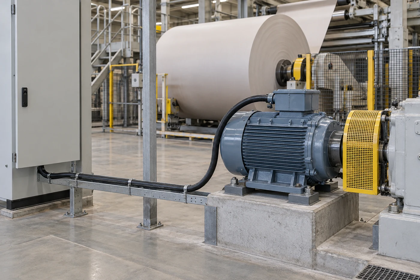
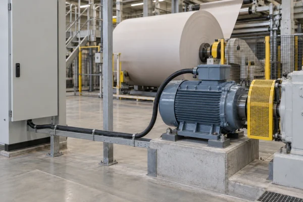
- Motor connections in paper-processing machinery.
- Chemical-process plant and heavy industrial drive systems.
- Fixed routes in dry, damp or wet areas, including outdoor routes using the black-sheath design.
- Occasional non-automated movement within the specified radius and temperature limits.
Drive-system selection
Confirm motor-lead length and the converter manufacturer's limits before choosing the cross-section. The capacitance table helps compare the selected configuration; filters, bonding and motor-bearing protection remain system-design decisions.
Use broad circumferential screen termination according to the drive and motor instructions. Review the braided cable shielding guide when planning the screen connection. This construction is intended for occasional free movement without compulsory guidance; continuous drag-chain cycling or torsion requires a cable documented for that duty.
Choosing between related motor cables
This page specifies the black-sheath 3+3 arrangement. The related 2YSLCYK-J uses four equal-size cores and one PE core, while 2XSLCYK-J uses XLPE insulation. The transparent-sheath 2YSLCY-JB range is a separate construction. Retain the full configuration on the order rather than relying on suffixes alone.
Specifications
| Parameter | Value |
|---|---|
| Rated voltage U₀/U | 600/1000 V (0.6/1 kV). |
| Test voltage | Core/core: 4000 V; core/screen: 4000 V. |
| Fixed-installation temperature | Minimum −40 °C for fixed installation; maximum conductor temperature +70 °C. |
| Occasional-movement temperature | Minimum −15 °C during occasional movement; maximum conductor temperature +70 °C. |
| Minimum bend radius, fixed | 4 × cable outside diameter D. |
| Minimum bend radius, occasional movement | 15 × cable outside diameter D. |
| Maximum tensile stress | 15 N/mm² of conductor cross-section during installation and operation. |
| Specific volume resistivity at 20 °C | >20 GΩ·cm. |
| Transfer impedance | Maximum 250 Ω/km at 30 MHz for this reference design. |
Symmetrical 3+3 size data
Nominal reference-design dimensions and approximate weights are shown below. Confirm finished values for the selected order. Each G value is the cross-section of one of the three green/yellow PE cores, not their combined area.
| Model and configuration (mm²) | Nominal OD (mm) | Copper index (kg/km) | Approx. weight (kg/km) | Reference current at 30 °C (A) |
|---|---|---|---|---|
| 2YSLCYK-JB 3 X 1.5 + 3 G 0.25 | 11.4 | 88 | 140 | 18 |
| 2YSLCYK-JB 3 X 2.5 + 3 G 0.5 | 12.2 | 144 | 230 | 26 |
| 2YSLCYK-JB 3 X 4 + 3 G 0.75 | 14.4 | 224 | 323 | 34 |
| 2YSLCYK-JB 3 X 6 + 3 G 1 | 15.7 | 276 | 420 | 44 |
| 2YSLCYK-JB 3 X 10 + 3 G 1.5 | 18 | 491 | 635 | 61 |
| 2YSLCYK-JB 3 X 16 + 3 G 2.5 | 20.2 | 723 | 930 | 82 |
| 2YSLCYK-JB 3 X 25 + 3 G 4 | 23.8 | 1136 | 1350 | 108 |
| 2YSLCYK-JB 3 X 35 + 3 G 6 | 26.9 | 1535 | 1780 | 135 |
| 2YSLCYK-JB 3 X 50 + 3 G 10 | 32.6 | 2156 | 2530 | 168 |
| 2YSLCYK-JB 3 X 70 + 3 G 10 | 36.4 | 2871 | 3225 | 207 |
| 2YSLCYK-JB 3 X 95 + 3 G 16 | 42 | 3953 | 4511 | 250 |
| 2YSLCYK-JB 3 X 120 + 3 G 16 | 47.8 | 4836 | 5663 | 292 |
| 2YSLCYK-JB 3 X 150 + 3 G 25 | 51.6 | 5412 | 6720 | 335 |
| 2YSLCYK-JB 3 X 185 + 3 G 35 | 56.5 | 7041 | 7855 | 382 |
| 2YSLCYK-JB 3 X 240 + 3 G 50 | 65.1 | 8986 | 9770 | 453 |
Current figures are reference ratings at 30 °C. Verify permissible current against the installation method, grouping, ambient conditions and drive duty. Copper index is a commercial reference quantity and is separate from the finished cable weight.
Electrical characteristics by configuration
Capacitance and inductance are stated at 800 Hz. Transfer impedance is stated at 30 MHz. These reference values support comparison of the selected cable size; they do not define a universal maximum motor-lead length.
| Model and configuration (mm²) | Inductance per core (µH/km) | Capacitance core/core (nF/km) | Capacitance core/screen (nF/km) | Transfer impedance at 30 MHz (Ω/km) |
|---|---|---|---|---|
| 2YSLCYK-JB 3 X 1.5 + 3 G 0.25 | 366 | 70 | 110 | 240 |
| 2YSLCYK-JB 3 X 2.5 + 3 G 0.5 | 340 | 80 | 130 | 210 |
| 2YSLCYK-JB 3 X 4 + 3 G 0.75 | 339 | 90 | 150 | 210 |
| 2YSLCYK-JB 3 X 6 + 3 G 1 | 321 | 90 | 150 | 150 |
| 2YSLCYK-JB 3 X 10 + 3 G 1.5 | 301 | 120 | 200 | 180 |
| 2YSLCYK-JB 3 X 16 + 3 G 2.5 | 285 | 140 | 230 | 190 |
| 2YSLCYK-JB 3 X 25 + 3 G 4 | 280 | 140 | 240 | 95 |
| 2YSLCYK-JB 3 X 35 + 3 G 6 | 271 | 150 | 260 | 85 |
| 2YSLCYK-JB 3 X 50 + 3 G 10 | 270 | 190 | 320 | 40 |
| 2YSLCYK-JB 3 X 70 + 3 G 10 | 262 | 190 | 320 | 45 |
| 2YSLCYK-JB 3 X 95 + 3 G 16 | 261 | 250 | 410 | 45 |
| 2YSLCYK-JB 3 X 120 + 3 G 16 | 256 | 260 | 430 | 45 |
| 2YSLCYK-JB 3 X 150 + 3 G 25 | 256 | 270 | 450 | 45 |
| 2YSLCYK-JB 3 X 185 + 3 G 35 | 255 | 280 | 470 | 45 |
| 2YSLCYK-JB 3 X 240 + 3 G 50 | 254 | 290 | 480 | 45 |
Standards
These references describe the conductor, insulation, sheath and test basis of the specified 3+3 design.
| Parameter | Value |
|---|---|
| Conductor construction | IEC 60228 / EN IEC 60228, class 5. |
| Cable design references | DIN VDE 0276-603 / HD 603 S1 + A3; DIN 57250-1 / VDE 0250-1. |
| PE insulation reference | EN 50290-2-23, table 1, LD/MD compound reference. |
| Core identification | HD 308 S2 / VDE 0293-308. |
| PVC sheath reference | TM4 according to EN 50363-4-1. |
| Flame test | IEC 60332-1-2 / EN 60332-1-2. |
| UV-resistance reference | EN 50525-1 for the black-sheath construction. |
| Material and electrical test references | IEC / EN 60811, EN 50395 and EN 50396. |
| Voltage tests | Core/core: 4 kV; core/screen: 4 kV. |
The official IEC 60228 conductor standard explains conductor classification and resistance requirements. Specify the required inspection records with the final phase-and-earth configuration.
Related cable options
Compare these cable options by service combination, movement, load, voltage and transmission requirement.
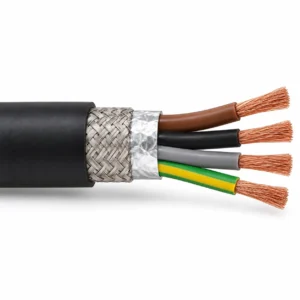
2XSLCYK-J 0.6/1 kV XLPE VFD Motor Cable
A related cable option for a different application or duty profile.
View product
2YSLCYK-J 0.6/1 kV Single-PE VFD Motor Cable
A related cable option for a different application or duty profile.
View product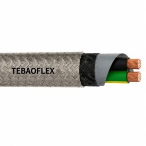
2YSLCY-JB Servo Motor Cable
A related cable option for a different application or duty profile.
View productRequest a cable recommendation and quotation
Send the required services, cable length, mechanical duty, environment, termination and quantity. Our team will review the application before quoting.
- Include the product name or SKU plus the required cable length and quantity.
- Attach a specification, drawing or data sheet when available.