

High Current Silicone High Voltage Wire, 20–60 kV DC
High current silicone high voltage wire for internal equipment leads: 20–60 kV DC, AWG 8 / 6 / 4 / 2 and a 150 °C temperature rating.
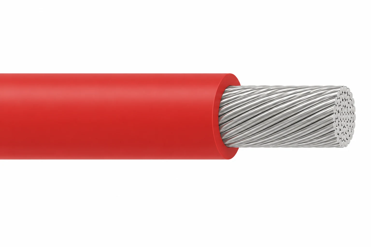
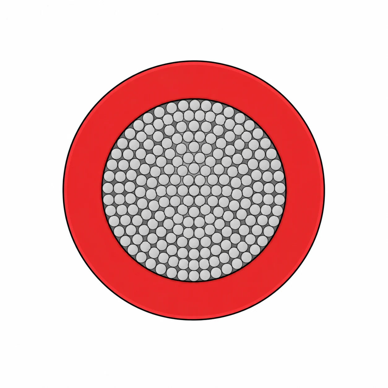
- 133-strand tinned-copper conductor with silicone insulation
- Unshielded, single core, with no separate outer jacket
- Nominal outside diameters from 6.9 to 16.5 mm, depending on voltage and conductor size
- Current, waveform and installation conditions assessed for the application
Large-conductor silicone leads for high-voltage equipment
High current silicone high voltage wire is an unshielded, single-conductor equipment lead with 20–60 kV DC voltage options, AWG 8, 6, 4 and 2 tinned-copper conductors, and a 150 °C temperature rating. Its 133-strand conductor sits inside one silicone insulation layer. The construction has no metallic screen or separate outer jacket.
Conductor size and insulation thickness solve different selection problems. The conductor must suit the circuit current and its thermal conditions; the insulation must suit the specified DC working voltage. At AWG 8, nominal outside diameter increases from 6.9 mm at 20 kV DC to 12.2 mm at 60 kV DC. At AWG 2, the corresponding diameters are 11.2 mm and 16.5 mm. These differences affect terminal selection, cable entry space and routing inside the equipment.
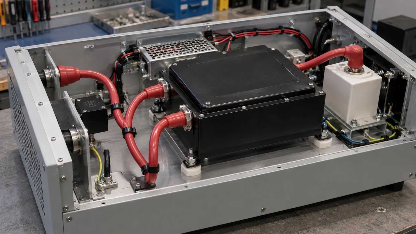
This family addresses larger-conductor internal leads for heaters, ovens, dryers, motors, generators and corona-treatment equipment. For current selection, specify continuous and peak current, duty cycle, ambient temperature and grouping. For AC or repetitive-pulse service, include the waveform and operating duration so the suitable construction can be evaluated.
For smaller lead sizes and the existing UL 3239 / UL 10475 options, compare high voltage silicone wire. The High Voltage DC & Test Cables category and silicone high-voltage cable selection guide explain the adjacent construction choices.
Construction
- Conductor: tinned copper, 133 strands. Conductor sizes are AWG 8, 6, 4 and 2; the strand gauges vary with conductor size.
- Insulation: silicone, with the finished diameter selected for the required 20–60 kV DC class.
Space for copper and space for insulation
Increasing the conductor size changes termination requirements as well as finished diameter. Select a terminal for the conductor area and stranding, then check its entry dimensions against the insulated wire. Use the nominal diameters in Specifications for initial layout and the agreed production drawing for final fit.
Red insulation is shown as one colour option. Specify the identification colour and marking required for your equipment.
Applications
This construction is intended for internal high-voltage equipment wiring where a larger copper conductor is required alongside a thick, flexible silicone dielectric.
- Heaters, furnaces, ovens and dryers: internal leads where the cable temperature must remain within the selected 150 °C limit.
- Motors and generators: equipment connections with a defined voltage waveform, conductor current and thermal duty.
- Corona-treatment equipment: internal high-voltage leads with the working waveform and termination arrangement assessed as part of the equipment design.
Selection boundaries
Route the lead where ambient temperature and conductor self-heating remain within the selected 150 °C cable rating. For moving installations, include the bend pattern and expected cycles in the enquiry.
This unscreened lead does not provide a metallic return or EMC screen. For a screened equipment connection, compare shielded silicone high voltage cable. For a construction with a conductor semiconductive layer, compare semiconductive-layer silicone high voltage wire; that layer is not a metallic shield.
This family is designed for internal equipment leads. For field wiring or completed high-voltage assemblies, include the installation and termination requirements with the enquiry.
Specifications
| Parameter | Value / condition |
|---|---|
| Working-voltage options | 20, 25, 30, 35, 40, 45, 50, 55 and 60 kV DC |
| Temperature rating | 150 °C |
| Conductor | Tinned copper, AWG 8 / 6 / 4 / 2; 133 strands |
| Insulation | Silicone |
| Screen / separate jacket | None |
| Installation | Internal equipment wiring |
| AC or pulse duty | Define waveform, frequency and duty cycle for engineering assessment |
| Current rating | To be established from circuit current, ambient temperature, grouping and installation |
| Minimum bend radius / proof test | To be confirmed for the agreed construction and test procedure |
| Conductor size | Strand construction | Metal area (mm²) | Nominal conductor diameter (mm) |
|---|---|---|---|
| AWG 8 | 133 × AWG 29 | 8.54 | 4.3 |
| AWG 6 | 133 × AWG 27 | 13.6 | 5.4 |
| AWG 4 | 133 × AWG 25 | 21.5 | 6.8 |
| AWG 2 | 133 × AWG 23 | 34.3 | 8.5 |
| DC voltage (kV) | AWG 8 OD (mm) | AWG 6 OD (mm) | AWG 4 OD (mm) | AWG 2 OD (mm) |
|---|---|---|---|---|
| 20 | 6.9 | 8.0 | 9.5 | 11.2 |
| 25 | 7.5 | 8.6 | 10.0 | 11.8 |
| 30 | 8.1 | 9.3 | 10.7 | 12.4 |
| 35 | 8.6 | 9.8 | 11.2 | 12.9 |
| 40 | 9.2 | 10.4 | 11.8 | 13.5 |
| 45 | 10.5 | 11.6 | 13.0 | 14.7 |
| 50 | 11.5 | 12.6 | 14.0 | 15.7 |
| 55 | 11.9 | 13.0 | 14.4 | 16.1 |
| 60 | 12.2 | 13.3 | 14.8 | 16.5 |
The table lists nominal diameters for this 133-strand, 150 °C family. Provide cable-entry and termination tolerances so the finished diameter can be agreed on the production drawing.
Choosing conductor size without inventing an ampere rating
For current selection, provide continuous and peak current, duty cycle, ambient temperature, run length, grouping and termination details. The cable and terminations can then be assessed together for thermal suitability.
DC working voltage, an AC proof test and a repetitive pulse rating describe different conditions. Include voltage waveform and duration in the enquiry; no AC or pulse rating is inferred from this DC table.
Standards
| Reference | Scope |
|---|---|
| UL 758 / AWM Style 3616 | Appliance wiring material; single conductor with extruded insulation for internal wiring. The configuration on this page is specified at 150 °C. |
| VW-1 | Vertical flame-test reference for this construction. |
| RoHS | Material-compliance reference; identify the required declaration in the purchase specification. |
Define the required style, voltage class, conductor size, temperature rating and acceptance tests together. An AWM style describes component-wire construction and use; the equipment assessment also determines how that wire is installed.
UL Solutions explains the distinction between component wiring and field-installation wire in its Wire and Cable Application Guide. Use the agreed cable drawing and equipment requirements to define the finished lead.
Related cable options
Compare these cable options by service combination, movement, load, voltage and transmission requirement.
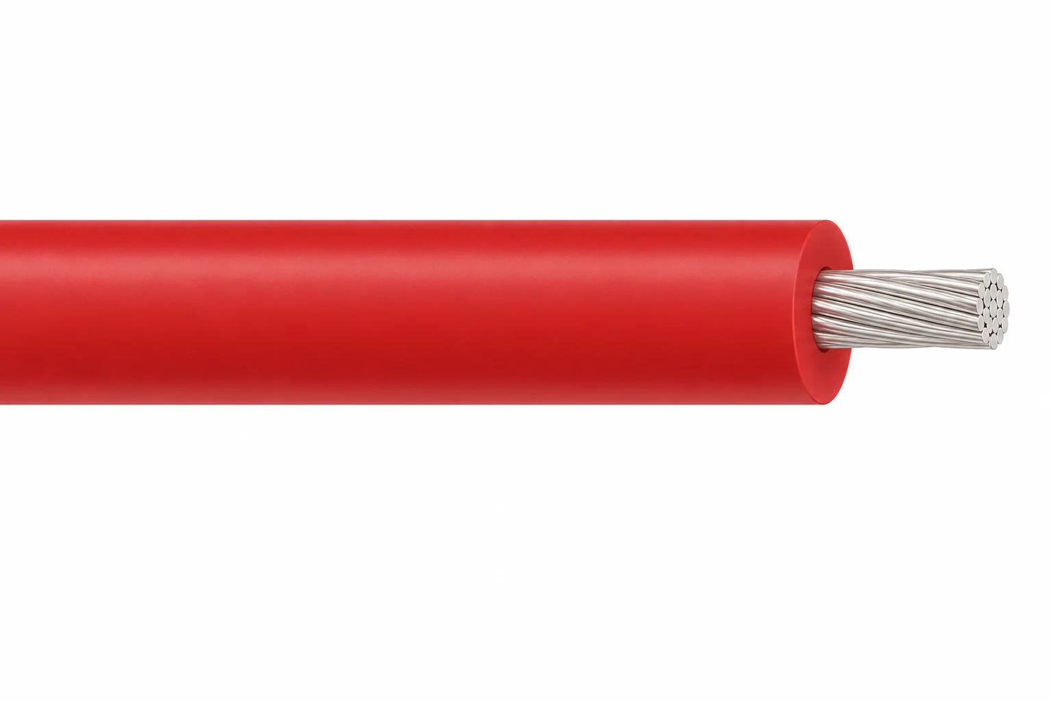
High Voltage Silicone Wire, 3–60 kV DC
A related cable option for a different application or duty profile.
View product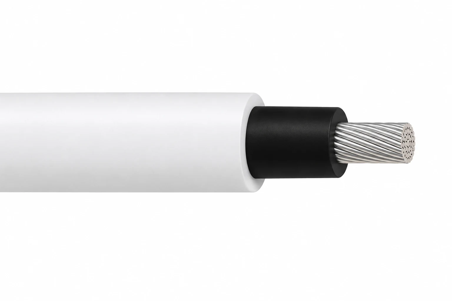
Semiconductive-Layer Silicone High Voltage Wire, 15–100 kV DC
A related cable option for a different application or duty profile.
View product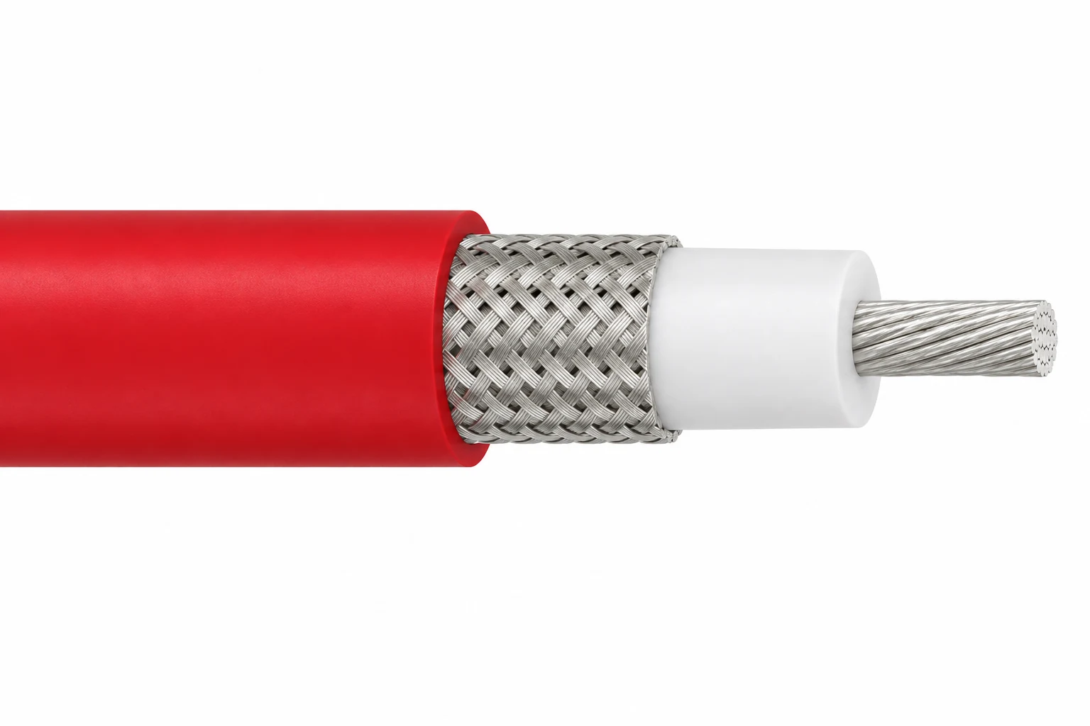
Shielded Silicone High Voltage Cable, 8–15 kV DC
A related cable option for a different application or duty profile.
View productRequest a cable recommendation and quotation
Send the required services, cable length, mechanical duty, environment, termination and quantity. Our team will review the application before quoting.
- Include the product name or SKU plus the required cable length and quantity.
- Attach a specification, drawing or data sheet when available.