

FEP High Voltage Wire, 18–30 kV DC
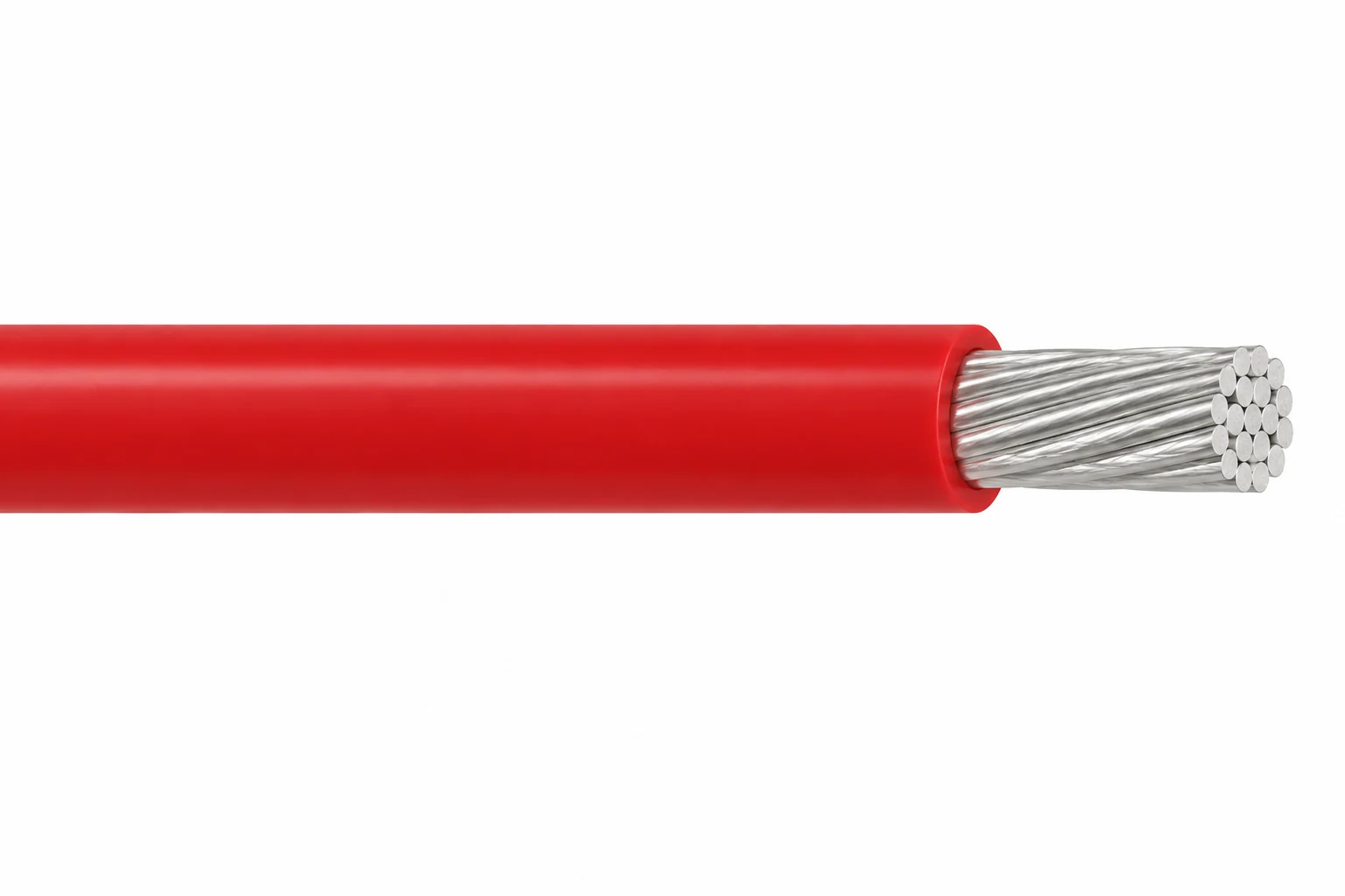
FEP high voltage wire combines silver-plated stranded copper with FEP insulation for compact internal equipment leads rated 18–30 kV DC. Choose the surface treatment to suit the potting material.
- Conductor sizes: 28–18 AWG; rating depends on the exact size and construction.
- Operating temperature: −55 to +200°C.
- Surfaces: plain FEP, pre-etched FEP for epoxy, or silicone-coated FEP for RTV/silicone.
- Construction: single conductor, unshielded.
- Minimum bend radius: 6 × finished diameter when fixed; 12 × when moving.
- Nominal finished diameter: 1.02–3.30 mm across the tabulated configurations.
For a quotation, specify the voltage, AWG size, surface treatment, potting system and required length.
FEP high voltage wire for compact equipment leads
FEP high voltage wire is an unshielded, single-conductor wire for internal connections in high-voltage equipment. This family covers 18–30 kV DC configurations with silver-plated stranded copper and a −55 to +200°C operating temperature range. Its distinguishing choice is the insulation surface: plain FEP, pre-etched FEP for epoxy potting, or a silicone coating for RTV and silicone-based potting systems.
Choose the electrical configuration and bonding surface together. A wire that fits a feedthrough may still require a different outer surface at an encapsulated joint. The configuration tables keep voltage, conductor stranding and diameter together, and distinguish the FEP dielectric diameter from the finished diameter of a coated wire.
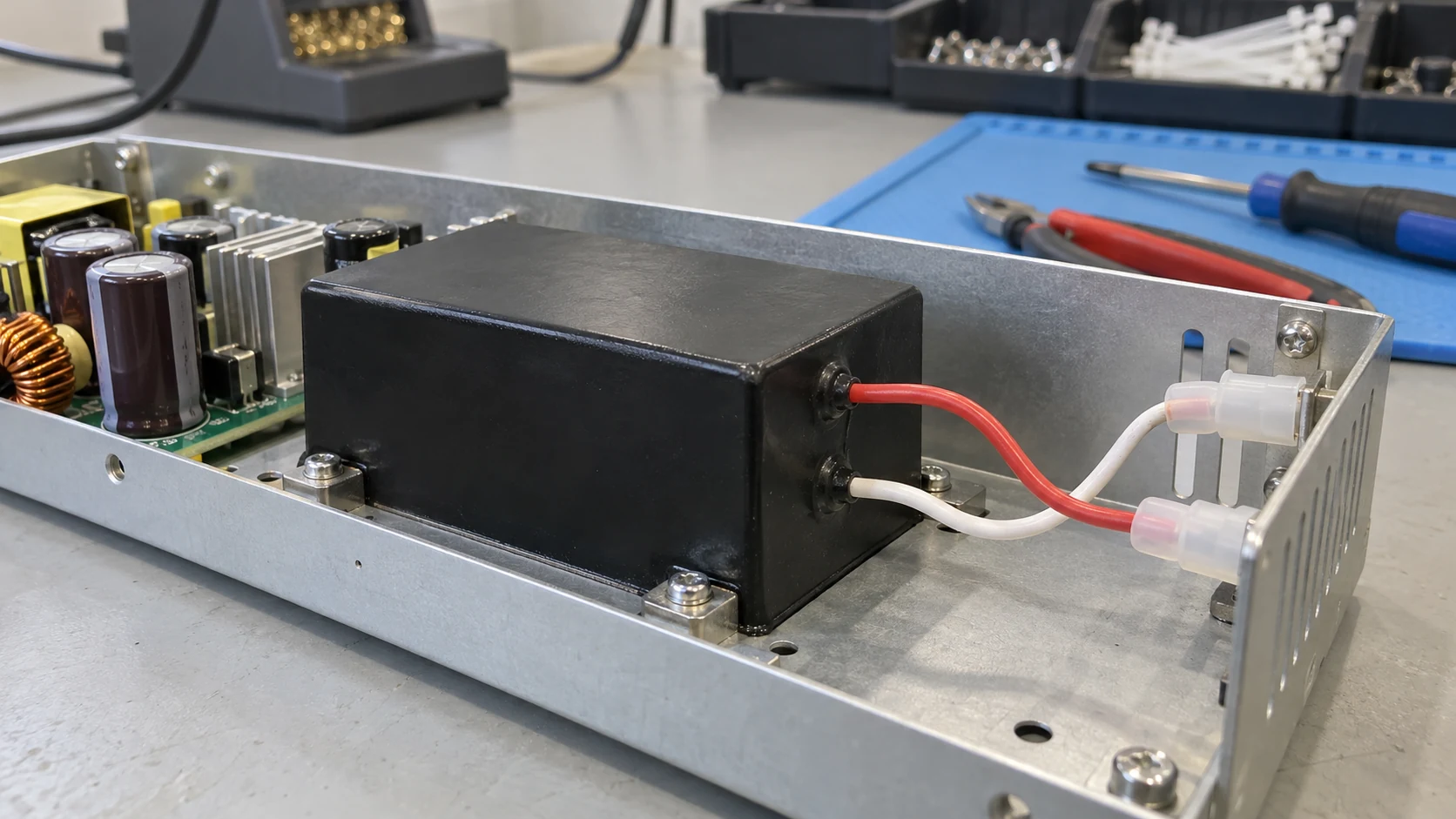
- Equipment fit: compact leads for power supplies, transformers and laser equipment where the connection remains inside a controlled enclosure.
- Assembly decision: identify the actual potting compound and cure process before selecting an etched or coated surface.
- Routing decision: check the finished diameter at feedthroughs, strain reliefs and bends, especially when adding a coating.
For AC or repetitive-pulse duty, send the waveform, operating duration and termination arrangement so the complete circuit can be assessed. Compare other constructions in High Voltage DC & Test Cables; the wire insulation temperature guide explains how material and complete-wire limits differ.
Construction
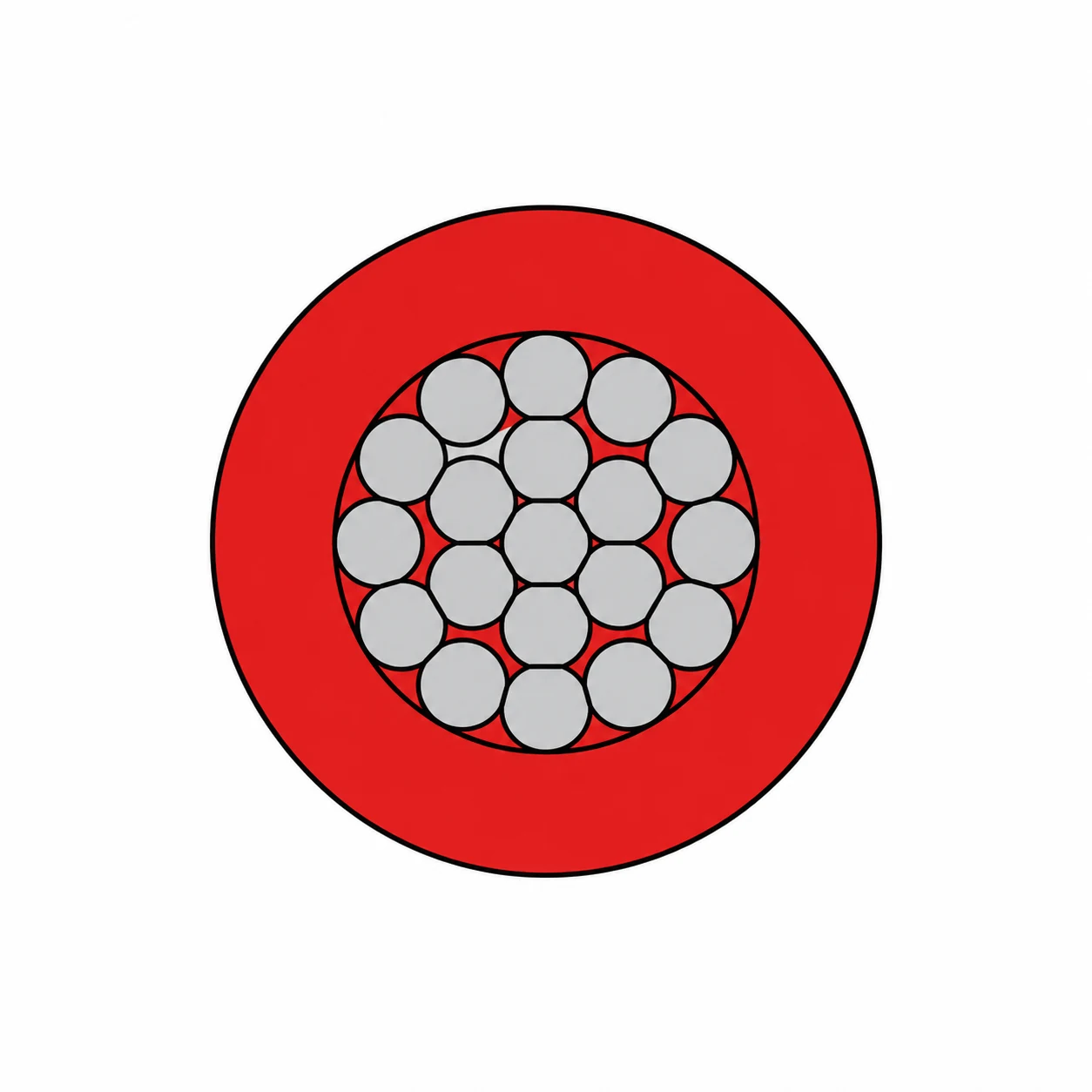
Every configuration uses one silver-plated stranded copper conductor with FEP as the electrical insulation. The surface option determines how the wire interfaces with an encapsulant.
| Element or option | Construction | Selection implication |
|---|---|---|
| Conductor | Silver-plated copper, 19 strands | Choose the AWG and strand size from the configuration table. |
| Plain insulation | FEP dielectric without an added coating | Use where the assembly does not require a pretreated bonding surface. |
| Pre-etched surface | Surface-treated FEP; no separate coating layer | Intended for bonding to epoxy-based potting materials. |
| Silicone coating | FEP dielectric with a silicone outer coating | Intended for RTV/silicone-based potting materials and adhesives. |
| Screening | No metallic screen | The equipment enclosure and circuit design must address screening needs. |
Control the bonding surface during assembly
For pre-etched wire, protect the treated surface from ultraviolet light during storage. The stated normal etching shelf life is six months or longer under that protection; check treatment age, handling and bond performance with the intended potting process. A silicone coating changes the finished diameter, so check the coated value before selecting feedthroughs or strain reliefs.
Applications
Use this compact FEP lead family for internal high-voltage connections in equipment where temperature, available space and potting compatibility determine wire selection.
- High-voltage power supplies: internal DC leads between insulated modules and equipment interfaces.
- Transformers: leads requiring a surface compatible with the selected encapsulation compound.
- Laser equipment: compact internal leads where the complete circuit waveform and insulation coordination are reviewed.
- Industrial and medical equipment: internal wiring selected against the end equipment requirements.
Match the potting process and duty
Specify epoxy or RTV/silicone chemistry, cure conditions and the required adhesive bond when choosing plain, etched or silicone-coated FEP. Assess the cable, potting, feedthrough and termination as one insulation system. Include the waveform and operating duration for AC or repetitive-pulse applications.
This family is for equipment and test connections. Include operating duration, continuous-duty requirements and any repetitive-motion conditions with the enquiry, together with the proposed routing radius.
Specifications
FEP high voltage wire is specified by voltage, conductor size and surface option. Dimensions below are nominal. The plain/pre-etched table represents eight plain and six pre-etched configurations; the coated table adds five configurations.
| Property | Value or condition |
|---|---|
| Rated DC voltage | 18, 20, 25 or 30 kV DC, as specified per row |
| Conductor size range | 28–18 AWG |
| Operating temperature | −55 to +200°C |
| Minimum bend radius, fixed | 6 × finished wire diameter |
| Minimum bend radius, moving | 12 × finished wire diameter |
| Nominal diameter, plain/pre-etched | 1.02–3.30 mm |
| Nominal finished diameter, silicone-coated | 1.32–2.79 mm |
| Colour selection | Black, brown, red, orange, yellow, green, blue, violet, grey, white or natural; specify with the construction enquiry |
Plain and pre-etched FEP configurations
| Configuration | Conductor strands (number/AWG) | Plain FEP | Pre-etched FEP | Nominal outer diameter (mm) |
|---|---|---|---|---|
| FEP wire 18 kV DC / 28 AWG | 19/40 | Yes | Yes | 1.02 |
| FEP wire 18 kV DC / 26 AWG | 19/38 | Yes | Yes | 1.14 |
| FEP wire 20 kV DC / 26 AWG | 19/38 | Yes | No tabulated configuration | 1.27 |
| FEP wire 18 kV DC / 24 AWG | 19/36 | Yes | Yes | 1.27 |
| FEP wire 20 kV DC / 22 AWG | 19/34 | Yes | Yes | 1.52 |
| FEP wire 25 kV DC / 20 AWG | 19/32 | Yes | Yes | 2.03 |
| FEP wire 30 kV DC / 20 AWG | 19/32 | Yes | Yes | 2.54 |
| FEP wire 30 kV DC / 18 AWG | 19/30 | Yes | No tabulated configuration | 3.30 |
Silicone-coated FEP configurations
| Configuration | Conductor strands (number/AWG) | FEP dielectric diameter (mm) | Finished outer diameter (mm) |
|---|---|---|---|
| Silicone-coated FEP wire 18 kV DC / 28 AWG | 19/40 | 1.02 | 1.32 |
| Silicone-coated FEP wire 18 kV DC / 24 AWG | 19/36 | 1.27 | 1.52 |
| Silicone-coated FEP wire 20 kV DC / 22 AWG | 19/34 | 1.52 | 1.78 |
| Silicone-coated FEP wire 25 kV DC / 20 AWG | 19/32 | 2.03 | 2.29 |
| Silicone-coated FEP wire 30 kV DC / 20 AWG | 19/32 | 2.54 | 2.79 |
Specify the complete configuration
An enquiry such as “FEP wire, 30 kV DC, 20 AWG, 19/32 stranding, pre-etched surface” identifies the construction more clearly than voltage alone. Add colour, length, operating duration, route and termination details. Include current and ambient conditions for conductor sizing.
Standards
| Reference | Stated scope |
|---|---|
| MIL-W-22759 | Wire specification reference. |
| UL 94 V-0 | FEP resin flammability requirement. |
| RoHS | Compliant. |
The UL 94 statement concerns the FEP resin. UL explains the scope of UL 94 material flammability ratings; use the equipment specification to establish the required finished-wire and assembly tests.
Include the required inspection documents, dielectric test method, acceptance limits and operating waveform with the technical enquiry. The project test conditions should be agreed for the selected configuration and terminations.
Related cable options
Compare these cable options by service combination, movement, load, voltage and transmission requirement.
PFA High Voltage Wire, 2 kV DC
A related cable option for a different application or duty profile.
View product
High Voltage Silicone Wire, 3–60 kV DC
A related cable option for a different application or duty profile.
View product
Semiconductive-Layer Silicone High Voltage Wire, 15–100 kV DC
A related cable option for a different application or duty profile.
View productRequest a cable recommendation and quotation
Send the required services, cable length, mechanical duty, environment, termination and quantity. Our team will review the application before quoting.
- Include the product name or SKU plus the required cable length and quantity.
- Attach a specification, drawing or data sheet when available.