

Semiconductive-Layer Silicone High Voltage Wire, 15–100 kV DC
Unshielded silicone high voltage wire with silver-plated copper and a conductor-facing semiconductive layer. Six configurations cover 15–100 kV DC, 0.97–8.5 mm² and operating temperatures up to +200°C. White insulation; configuration-specific fixed bends and conditional short-term AC limits.
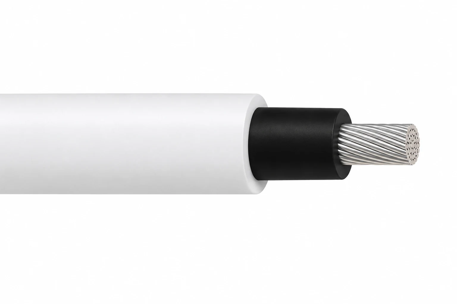
Semiconductive-layer silicone high voltage wire is an unshielded, single-conductor lead for internal high voltage equipment and test connections. The configurations on this page cover 15–100 kV DC, with silver-plated copper strands, a black semiconductive silicone layer around the conductor, and white silicone insulation. All six configurations have an upper operating temperature of +200°C; the lower limit is −65°C for the 15–80 kV versions and −51°C for the 100 kV version.
The conductor-facing semiconductive layer creates a smoother electrical interface around the strand bundle. It is a different construction from insulation-only silicone high voltage wire. Selection therefore needs the complete layer arrangement as well as the voltage and conductor area. The semiconductive layer is not a metallic screen or a protective-earth conductor.
Use the configuration tables to compare conductor size, diameter, temperature and fixed bending radius together. Two wires with the same outside diameter can have different conductor areas and voltage limits. For short-term 50 Hz AC duty, send the expected operating duration and partial-discharge control requirements with the selected configuration.
For a quotation, provide the operating waveform, energization time, conductor area, routing space and termination drawing. Final operating duty and the selected dimensions are confirmed for the equipment. Compare other high voltage DC and test cable constructions, or use the high voltage silicone cable selection guide for the wider application context.
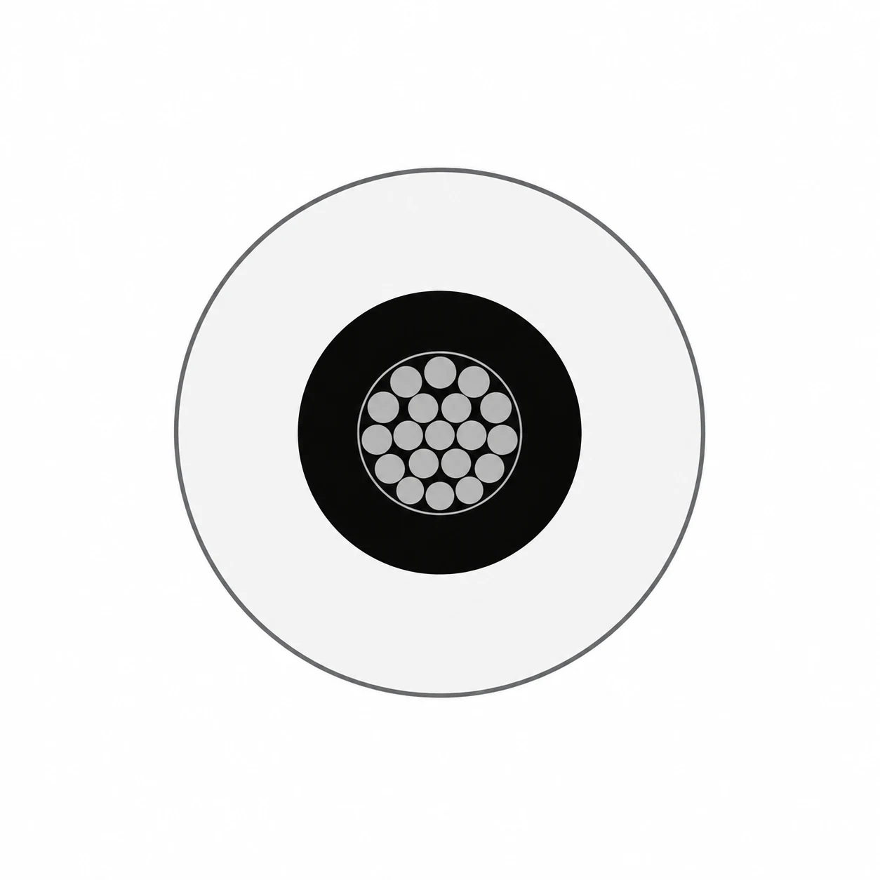
Three-layer unshielded construction
- Conductor: stranded silver-plated copper. The documented configurations use 19-strand constructions or, for 100 kV DC, 133 strands.
- Conductor-facing semiconductive layer: black semiconductive silicone around the conductor bundle.
- Dielectric: white silicone insulation forming the outside of the wire.
There is no metallic braid, armour or separate outer jacket in these configurations. The black layer remains part of the electrical insulation design; its termination length and handling must follow the equipment drawing.
The semiconductive layer smooths the conductor interface. Specify partial-discharge controls, clearances and terminations for the complete equipment layout.
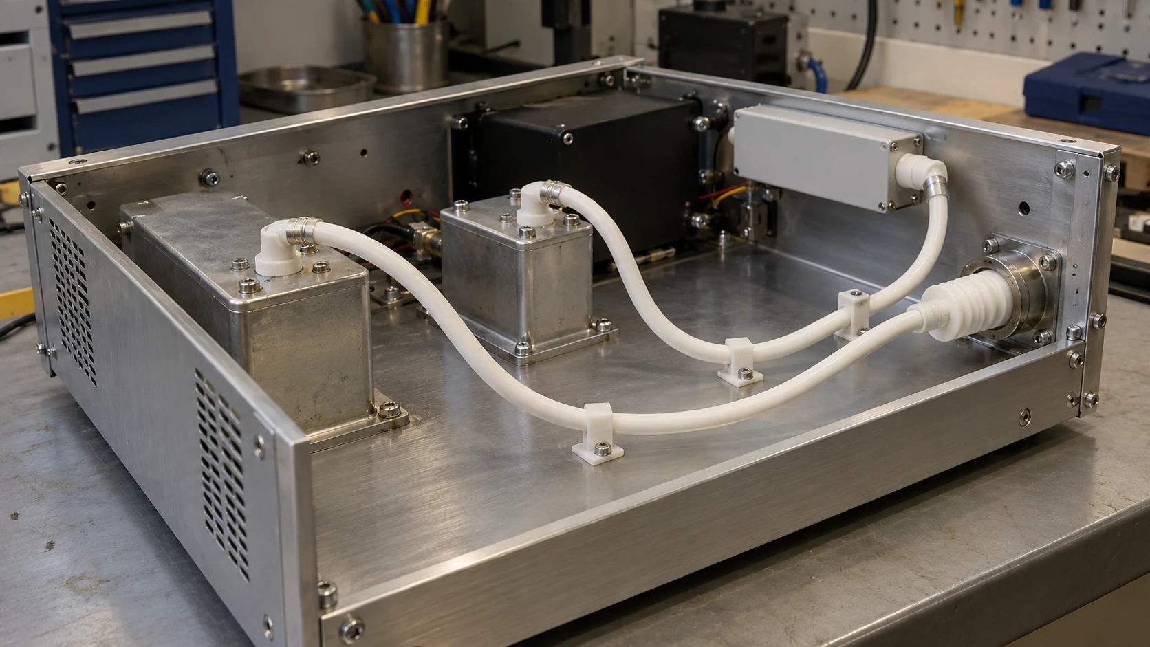
Internal high voltage equipment and test connections
These wires are intended for insulated connections within high voltage equipment, laboratory apparatus and test or measurement systems. Their construction is useful where a semiconductive conductor interface is specified and the wire must operate within the stated thermal range.
- Equipment wiring: select by conductor area and the complete insulation geometry, allowing space for the specified fixed bend and termination.
- Test connections: define DC, AC or pulsed operation, duration and repetition before selecting a voltage configuration.
- Heated enclosures: compare the complete temperature range, including the different −51°C lower limit of the 100 kV configuration.
Installation and operating boundaries
The published bends are fixed-installation values. Repeated flexing, cable-chain, reeling and torsion duty require a separate assessment. Route the unshielded lead away from conductive edges and specify the required supports, clearance and termination geometry in the equipment design.
The catalogue scope is high voltage equipment and test work. Select a purpose-designed power cable for permanent utility transmission or distribution. For continuous energization, AC operation or pulse duty, agree the application-specific operating voltage and partial-discharge criteria before ordering.
Configuration dimensions
Each row identifies a complete semiconductive silicone wire configuration. Diameter and weight are nominal or approximate selection values; final order dimensions are confirmed with the quotation. Conductor areas below preserve the documented values rather than substituting an AWG conversion.
| Configuration | Conductor size | Silver-plated copper stranding | Conductor Ø (mm) | Over semiconductive layer Ø (mm) | Wire outside Ø (mm) |
|---|---|---|---|---|---|
| 15 kV DC / 3.1 mm² | AWG12 / 3.1 mm² | 19 × AWG25 | 2.4 | 3.6 | 6.0 |
| 40 kV DC / 0.97 mm² | AWG18 / 0.97 mm² | 19 × AWG30 | 1.24 | 2.3 | 6.0 |
| 50 kV DC / 1.2 mm² | AWG16 / 1.2 mm² | 19 × AWG29 | 1.5 | 2.8 | 7.5 |
| 60 kV DC / 3.1 mm² | AWG12 / 3.1 mm² | 19 × AWG25 | 2.4 | 3.8 | 9.1 |
| 80 kV DC / 3.1 mm² | AWG12 / 3.1 mm² | 19 × AWG25 | 2.4 | 3.6 | 10.7 |
| 100 kV DC / 8.5 mm² | AWG8 / 8.5 mm² | 133 × AWG29 | 4.2 | 5.6 | 16.5 |
| Configuration | Rated DC voltage (kV) | Operating temperature (°C) | Minimum fixed bend radius (mm) | Approx. weight (kg/m) |
|---|---|---|---|---|
| 15 kV DC / 3.1 mm² | 15 | −65 to +200 | 13 | 0.046 |
| 40 kV DC / 0.97 mm² | 40 | −65 to +200 | 10 | 0.045 |
| 50 kV DC / 1.2 mm² | 50 | −65 to +200 | 13 | 0.064 |
| 60 kV DC / 3.1 mm² | 60 | −65 to +200 | 13 | 0.112 |
| 80 kV DC / 3.1 mm² | 80 | −65 to +200 | 25 | 0.149 |
| 100 kV DC / 8.5 mm² | 100 | −51 to +200 | 64 | 0.373 |
Short-term AC operation
The table lists short-term 50 Hz AC operating limits with suitable partial-discharge control. Specify the permitted duration and installed cable-and-termination arrangement to determine the operating voltage for the equipment.
| DC configuration | Short-term AC limit (kV RMS) | Conditions |
|---|---|---|
| 15 kV DC / 3.1 mm² | 5 | 50 Hz; application-specific partial-discharge control and operating duration |
| 40 kV DC / 0.97 mm² | 15 | 50 Hz; application-specific partial-discharge control and operating duration |
| 50 kV DC / 1.2 mm² | 15 | 50 Hz; application-specific partial-discharge control and operating duration |
| 60 kV DC / 3.1 mm² | 20 | 50 Hz; application-specific partial-discharge control and operating duration |
| 80 kV DC / 3.1 mm² | Not specified | AC duty requires separate confirmation |
| 100 kV DC / 8.5 mm² | 30 | 50 Hz; application-specific partial-discharge control and operating duration |
Rated DC values identify the listed configurations. Continuous DC operation, voltage ripple, pulses and energization time must be specified for the equipment. No moving bend radius, current rating or quantitative partial-discharge limit is assigned to this family.
Material requirement and application qualification
- RoHS: RoHS compliance is specified for the six configurations. The European Commission RoHS overview explains the restriction of hazardous substances in electrical and electronic equipment.
- AC use: the short-term, 50 Hz limits in Specifications require suitable partial-discharge control and an application-specific operating voltage.
- Partial-discharge test planning: IEC 60270:2025 describes charge-based partial-discharge measurement under AC and DC test conditions. Specify the waveform, test voltage, duration and acceptance level when that assessment is required.
IEC 60270 is a measurement-method reference here. A project test schedule must define its acceptance criteria and the complete cable-and-termination arrangement.
Related cable options
Compare these cable options by service combination, movement, load, voltage and transmission requirement.
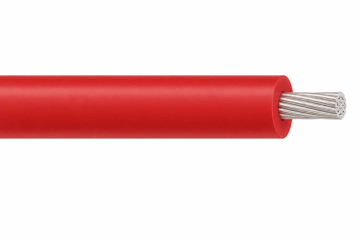
High Voltage Silicone Wire, 3–60 kV DC
A related cable option for a different application or duty profile.
View product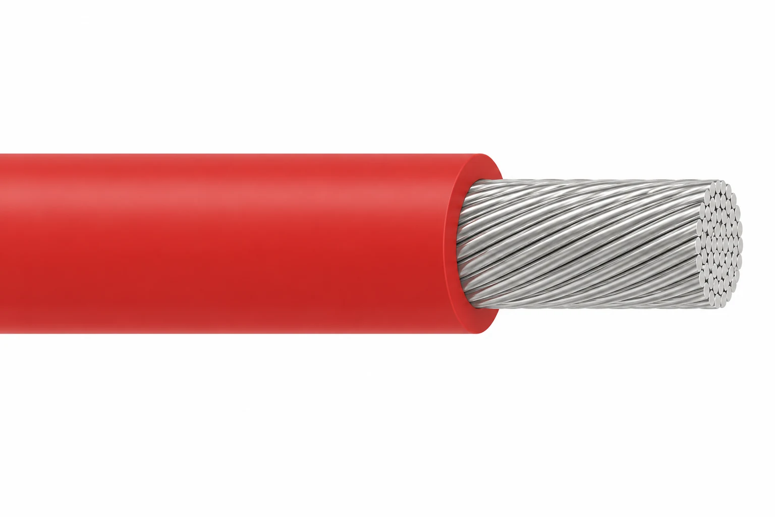
High Current Silicone High Voltage Wire, 20–60 kV DC
A related cable option for a different application or duty profile.
View product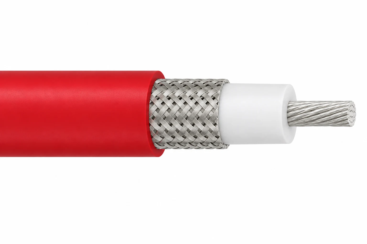
Shielded Silicone High Voltage Cable, 8–15 kV DC
A related cable option for a different application or duty profile.
View productRequest a cable recommendation and quotation
Send the required services, cable length, mechanical duty, environment, termination and quantity. Our team will review the application before quoting.
- Include the product name or SKU plus the required cable length and quantity.
- Attach a specification, drawing or data sheet when available.