












Mode 4 DC EV Charging Cable, 1.5 kV
Flexible 1.5 kV DC EV charging cable for the station-to-vehicle lead. Compare class 6 Mode 4 and class 5 S1BZ5-F / Type 126 constructions, keeping conductor counts, insulation, sheath, temperature and bend limits together.
DC EV charging cable carries power, protective earth and the specified control or pilot circuits between a charging station and the vehicle connection. This range covers a class 6 flexible Mode 4 construction and separate class 5 S1BZ5-F and Type 126 constructions. The DC voltage class is 1.5 kV; the additional AC rating is stated only for the relevant construction.
Start with the required circuit arrangement. A class 6 reference combines two DC power conductors, one protective-earth conductor and a six-core control/pilot group. Other tables use paired auxiliary circuits or a different power-core arrangement. Match the count and cross-section to the charger, vehicle connector and termination drawing before checking the outside diameter.
Select the complete material and operating envelope. The class 6 construction uses rubber insulation and a halogen-free polyurethane sheath. S1BZ5-F uses HEPR type EVI-2 insulation and an EVM-1 TPU sheath, while the Type 126 construction lists EVI-2 insulation and an EVM-1 sheath compound. Their conductor classes, bending rules, short-circuit conditions and installation temperatures are separate parameters.
Provide the DC voltage, current duty, ambient temperature, cut length and connector interface with the enquiry. Check the installed bend, pulling load and movement conditions together with the equipment design. The class 6 current table retains its 30°C basis and temperature correction factors. Terminate every power, earth and auxiliary core for its assigned circuit and provide mechanical strain relief at the lead ends.
Explore the industrial cable range for related configurations.
For lower-voltage AC charging leads and hybrid power-plus-signal dispenser assemblies, compare these EV charging cable constructions: EV Charging Power and Data Composite Cable, 0.6/1 kV (for 0.6/1 kV composite AC/DC charging cables combining main power cores with shielded data and control pairs); H05BZ5-F / H07BZ5-F EV Charging Cable (for 300/500 V and 450/750 V Mode 1–3 AC charging leads with halogen-free EVI-2 / PUR sheaths). Verify maximum DC bus voltage, thermal sensor pair count, and outdoor driveway abrasion resistance before ordering.
Construction
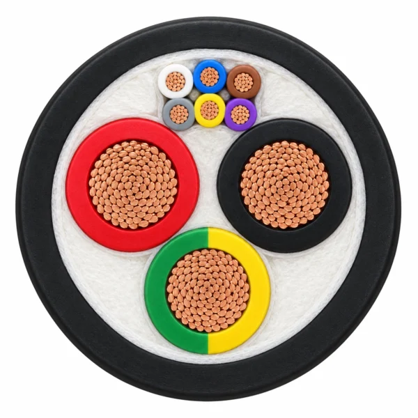
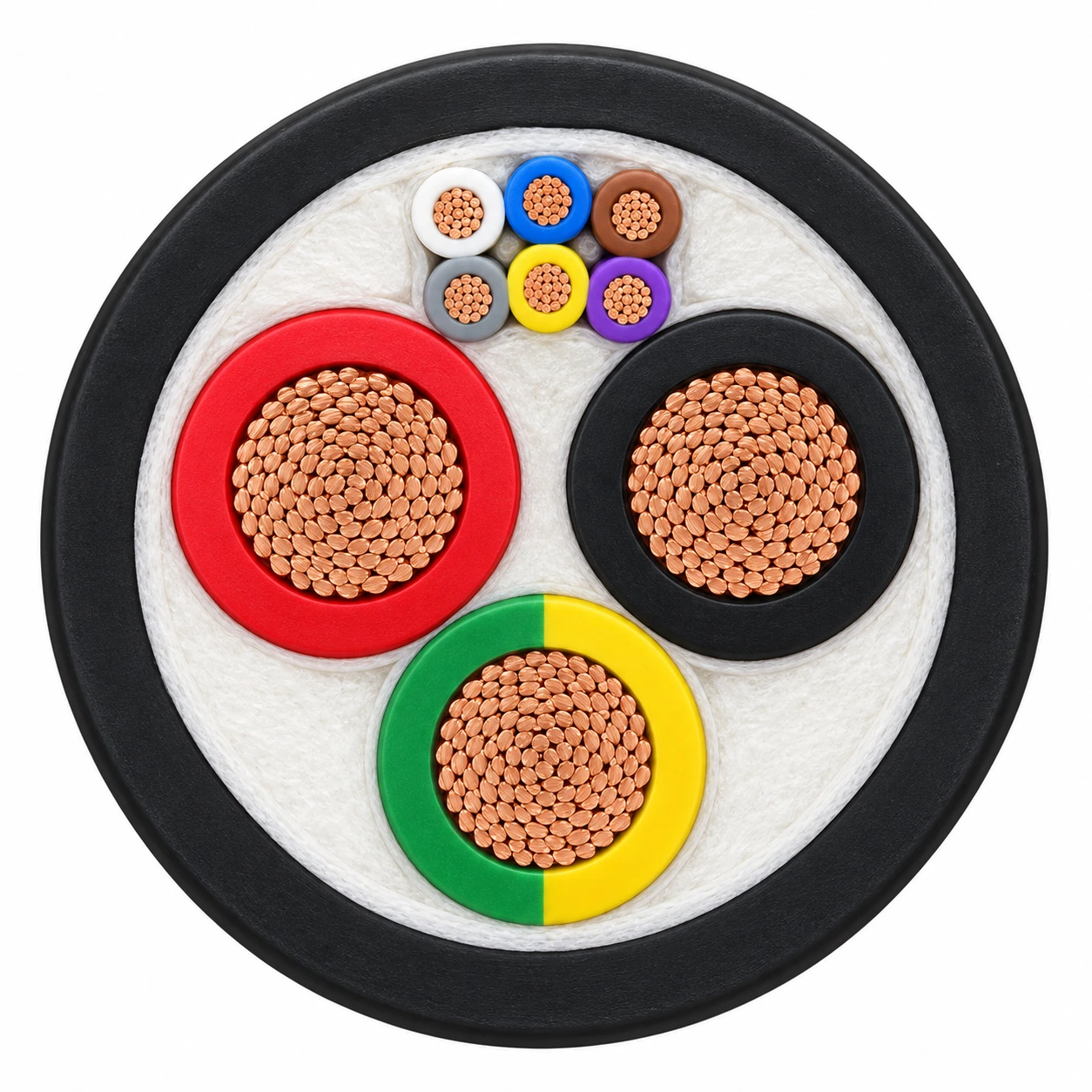
The representative class 6 Mode 4 cable is 2 × 16 + 1G16 mm² with 1 × (6 × 1 mm²) control/pilot conductors. It has three equal large insulated copper conductors in a compact triangular arrangement and six smaller auxiliary cores grouped above them, within a black PUR-HF sheath.
| Component | Material and construction |
|---|---|
| Class 6 Mode 4 power and earth | Two fine flexible copper DC power conductors and one protective-earth conductor; cross-sections are listed by configuration. |
| Class 6 Mode 4 auxiliary group | Six 1 mm² class 5 flexible copper control/pilot conductors with rubber insulation. |
| Class 6 Mode 4 insulation and sheath | Rubber insulation and halogen-free polyurethane outer sheath; black or orange sheath options. |
| S1BZ5-F conductors and insulation | Bare copper class 5 to EN / IEC 60228; HEPR type EVI-2 insulation, including the listed CC/CP circuits. |
| S1BZ5-F sheath | Special TPU type EVM-1, black. |
| Type 126 conductors | Annealed class 5 stranded bare copper to IEC 60228; tinned copper is a separately requested construction. |
| Type 126 insulation and sheath | Special EVI-2 insulation and EVM-1 outer-sheath compound according to IEC 62893-1; black sheath in the listed reference. |
| Circuit arrangement | Power, protective earth and auxiliary counts follow each row. No liquid-cooling channel or metallic armour is included in these reference constructions. |
Applications
Select a flexible Mode 4 lead for the charging-station-to-vehicle connection. Match the required power, protective-earth and control/pilot circuits to the connector system and charger design.
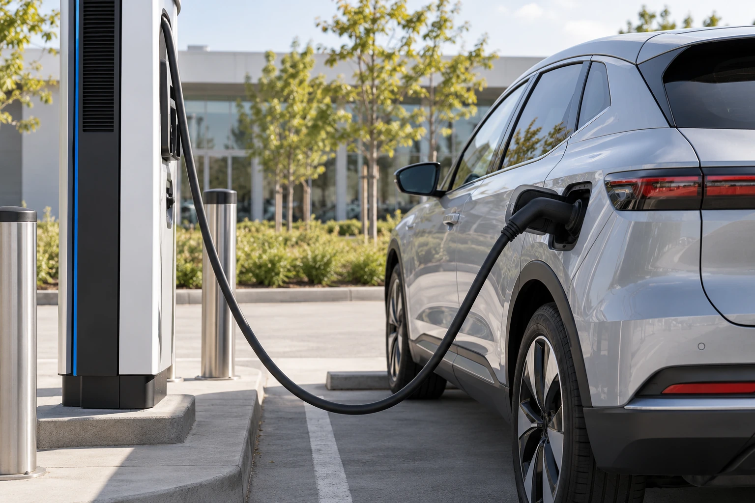
- Mode 4 DC vehicle charging leads for public and commercial charging stations.
- Trailing plug connections to the vehicle with cable movement controlled by the charger layout, bend limits and end supports.
- Class 6 flexible leads using the six-core auxiliary group or class 5 S1BZ5-F / Type 126 leads with the specified auxiliary configuration.
- The class 6 Mode 4 construction includes an AD7 temporary-immersion reference; define the actual water-exposure conditions with the equipment requirements.
- Select environmental, oil, UV, ozone and mechanical test requirements for the exact construction; retain its own standard references.
- Arrange strain relief, protective-earth termination and preparation of all auxiliary cores at the lead ends.
For jacket oil-resistance classifications on forecourt dispensers and shielded onboard EV battery cables, consult these references: Oil Resistant Cable: PR I vs PR II (comparing hydrocarbon, diesel, and hydraulic fluid immersion ratings for industrial elastomer and PUR jackets); FHLR2GCB2G Shielded EV Cable 0.6/1 kV (for 0.6/1 kV EMC-screened vehicle internal high-voltage traction interconnects). Confirm cooling mode, minimum cold-bend temperature, and gland sealing class.
Specifications
| Parameter | Value |
|---|---|
| Rated voltage, DC operation | 1.5 kV DC for the listed Mode 4, S1BZ5-F and Type 126 design families. |
| Additional voltage reference | Type 126: 0.6/1 kV AC. The S1BZ5-F reference also lists 600/1000 V. |
| Power conductor classes | Class 6 for the first Mode 4 reference; class 5 for S1BZ5-F and Type 126. |
| Conductor operating temperature | 90°C maximum for the listed design references. |
| Operating and movement temperature | Class 6 Mode 4 and Type 126: −40°C to +90°C operating range. S1BZ5-F: −40°C to +60°C ambient during fully flexible operation. |
| Tensile-load reference | 15 N/mm² on the conductors for the class 6 Mode 4 and S1BZ5-F constructions. |
| Minimum bend rules | Class 6 Mode 4: 5D. S1BZ5-F: VDE 0298-3. Type 126: 5D for D ≤ 12 mm and 6D for D > 12 mm in free movement. |
| Type 126 installation and storage | Minimum installation temperature −25°C; maximum storage temperature +45°C. |
| Reference power and earth configuration | Control/pilot configuration (mm²) | Nominal overall diameter (mm) | Nominal mass (kg/km) | Maximum DC current at 30°C (A) | Charging mode |
|---|---|---|---|---|---|
| Mode 4 class 6 2 × 16 + 1G16 mm² | 1 × (6 × 1) | 19.3 | 700 | 99 | 4 |
| Mode 4 class 6 2 × 25 + 1G16 mm² | 1 × (6 × 1) | 22.1 | 950 | 131 | 4 |
| Mode 4 class 6 2 × 35 + 1G16 mm² | 1 × (6 × 1) | 23.8 | 1150 | 162 | 4 |
| Mode 4 class 6 2 × 50 + 1G25 mm² | 1 × (6 × 1) | 27.7 | 1650 | 202 | 4 |
| Mode 4 class 6 2 × 70 + 1G35 mm² | 1 × (6 × 1) | 32.3 | 2250 | 250 | 4 |
| Mode 4 class 6 2 × 95 + 1G50 mm² | 1 × (6 × 1) | 37.3 | 3000 | 301 | 4 |
| Ambient temperature (°C) | Current correction factor |
|---|---|
| 30 | 1.0 |
| 35 | 0.91 |
| 40 | 0.82 |
| 45 | 0.71 |
| 50 | 0.58 |
| 55 | 0.41 |
| Model and conductor configuration (mm²) | Nominal insulation thickness (mm) | Approx. outer-sheath thickness (mm) | Overall diameter (mm) | Approx. mass (kg/km) |
|---|---|---|---|---|
| S1BZ5-F 3G16 + 3 × (2 × 0.75) | 0.8 | 1.5 | 20.6 | 680 |
| S1BZ5-F 2 × 35 + 1G16 + 3 × (2 × 0.75) | 1 | 1.9 | 24.8 | 1205 |
| S1BZ5-F 2 × 35 + 1G16 + 1 × (4 × 0.75) + 2 × (2 × 0.75) | 1 | 1.9 | 25.8 | 1350 |
| S1BZ5-F 2 × 35 + 1G25 + 3 × (2 × 0.75) | 1 | 1.9 | 26 | 1275 |
| S1BZ5-F 2 × 50 + 1G25 + 3 × (2 × 0.75) | 1.1 | 2.2 | 27.9 | 1600 |
| S1BZ5-F 2 × 70 + 1G35 + 3 × (2 × 0.75) | 1.2 | 2.5 | 32.7 | 2150 |
| S1BZ5-F 2 × 70 + 1G35 + 6 × 0.75 | 1.2 | 2.5 | 32.7 | 2150 |
| S1BZ5-F 2 × 95 + 1G50 + 3 × (2 × 0.75) | 1.2 | 2.7 | 41 | 2400 |
| S1BZ5-F 5G50 + 6 × 1.5 | 1.1 | 2.2 | 36.4 | 3065 |
| Model and conductor configuration (mm²) | Nominal insulation thicknesses (mm) | Nominal sheath thickness (mm) | Min. overall diameter (mm) | Max. overall diameter (mm) | Approx. mass (kg/km) | Free-movement bend radius (mm) |
|---|---|---|---|---|---|---|
| Type 126 DC 2 × 50 + 1G25 + 4 × (2 × 0.75) | 1.1 / 1 / 0.4 | 2.2 | 27.9 | 34.8 | 1595 | 209 |
| Type 126 DC 2 × 70 + 1G35 + 4 × (2 × 0.75) | 1.2 / 1 / 0.4 | 2.5 | 32.6 | 40.7 | 2220 | 244 |
| Type 126 DC 4 × 50 + 1G25 + 4 × (2 × 0.75) | 1.1 / 1 / 0.4 | 2.7 | 36 | 41 | 2845 | 246 |
| Construction | Operating or movement condition | Conductor maximum | Bend-radius rule |
|---|---|---|---|
| Class 6 Mode 4 | Operating range −40°C to +90°C | 90°C | 5D |
| S1BZ5-F | Fully flexible ambient −40°C to +60°C | 90°C | VDE 0298-3 |
| Type 126 | Operating range −40°C to +90°C; installation minimum −25°C | 90°C | Free movement: 5D at D ≤ 12 mm; 6D at D > 12 mm |
| Construction | Electrical or thermal condition | Reference value |
|---|---|---|
| Class 6 Mode 4 | Power-core electrical test | 3500 V DC |
| Class 6 Mode 4 | Control/pilot electrical test | 2000 V |
| Class 6 Mode 4 | Maximum short-circuit conductor temperature | 160°C |
| Type 126 bare copper | Maximum short-circuit conductor temperature | 250°C, maximum 5 s |
| Type 126 tinned copper option | Maximum short-circuit conductor temperature | 200°C, maximum 5 s |
The class 6 current values apply at 30°C ambient. Apply the listed ambient-temperature correction factor and coordinate the installed current with routing, loading and equipment conditions.
Each dimension row retains its conductor count and auxiliary grouping. Three pairs, four pairs, six individual auxiliary cores and a six-core grouped unit are different configurations.
The class 6 Mode 4 electrical test lists 3500 V DC for power cores and a separate 2000 V reference for control/pilot cores. These are test conditions, not additional operating ratings.
The Type 126 250°C and 200°C short-circuit limits apply to bare and tinned conductor constructions respectively, for a maximum of 5 s. Do not apply them to the class 6 160°C reference.
Select connector compatibility, circuit assignment, cut length, water-exposure conditions and installation support with the charger and vehicle-interface requirements.
Standards
| Standard or specification | Application |
|---|---|
| IEC 62893-4-1, type 62893 IEC 126 | Construction reference for the S1BZ5-F / Type 126 DC charging designs. |
| IEC 62893-1 / IEC 62821-1 | EVI-2 insulation, EVM-1 sheath and general or halogen-assessment references for the corresponding class 5 designs. |
| IEC / EN 61851-1 | Mode 4 charging-system reference; coordinate the cable and vehicle connection with the equipment system. |
| IEC / EN 60228 | Class 6 copper for the first reference; class 5 copper for the S1BZ5-F / Type 126 references. |
| IEC 62893 / EN 50620 | Cable-design references listed for the class 6 Mode 4 construction. |
| IEC 60332-1-2 / IEC 60811-404 | Flame-propagation and oil-resistance test references for the named charging-cable constructions. |
| DIN EN 50525-1 Annex B / DIN EN 50396 part 8.1.3 | S1BZ5-F combustion-gas and ozone references. |
| IEC 62893-2 / IEC 60245-2 / IEC 60227-2 | Electrical-test references for Type 126; IEC 62893-2 also supplies its weathering, water, tear and chemical-resistance test references. |
| IEC 62440 / EN 50565-1 table 3 | Use and bend-radius references for Type 126. |
| IEC 60364-5-52 | Type 126 current-carrying-capacity calculation reference for the actual installation. |
Related cable options
Compare these cable options by service combination, movement, load, voltage and transmission requirement.
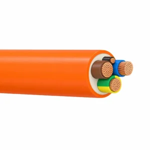
H05BZ5-F / H07BZ5-F EV Charging Cable
A related cable option for a different application or duty profile.
View product
EV Charging Power and Data Composite Cable, 0.6/1 kV
A related cable option for a different application or duty profile.
View product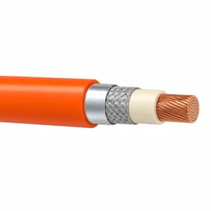
FHLR2GCB2G Shielded EV Cable 0.6/1 kV
A related cable option for a different application or duty profile.
View productRequest a cable recommendation and quotation
Send the required services, cable length, mechanical duty, environment, termination and quantity. Our team will review the application before quoting.
- Include the product name or SKU plus the required cable length and quantity.
- Attach a specification, drawing or data sheet when available.