








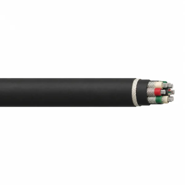
O2nGcekż-G2 0.6/1 kV Double-Sheath Mining Cable
O2nGcekż-G2 is a 0.6/1 kV trailing cable with six individually screened EPR power cores around a screened pilot group. Its black double polychloroprene sheath contains nonmetallic braid reinforcement. Match both power sets, the pilot arrangement and the protective-conductor connection when specifying a replacement. MOQ: 50 m; manufacturing lead time: 7–45 working days.
O2nGcekż-G2 mining cable supplies mobile mining equipment at 0.6/1 kV where two sets of three screened power cores are required in one flexible cable. The six power cores surround a screened group of pilot cores. A reinforced double rubber sheath distinguishes this construction from the single-sheath OnGcekż-G2 version.
Start with the complete equipment cable marking. Equal-size power sets and mixed-size sets have different circuit requirements, even when the finished cable diameter is similar. The pilot count, pilot area and protective-conductor connection also belong in the selection. A six-power-core G2 cable should not be chosen from the conductor area alone or replaced by a three-power-core mining cable simply because both carry a 0.6/1 kV rating.
The double sheath combines two polychloroprene rubber layers with textile reinforcement between them. Individual power-core screens and the screened central pilot assembly remain separate parts of the construction. Match their termination and earthing arrangements to the equipment drawing, along with the cable route and mechanical load. The tabulated configurations provide a starting point for checking cable entries, handling equipment and replacement dimensions.
Send the complete marking, both power-circuit sizes, pilot arrangement, required length and operating conditions for a quotation. TEBAOFLEX supplies this family from a 50 m minimum order quantity with a manufacturing lead time of 7–45 working days. The quotation can identify the required sheath version, colour coding, dimensional schedule and acceptance documents for the intended mine.
Explore the mining and tunneling cable range for related configurations.
Construction
This G2 construction uses six screened power cores around one common pilot assembly. The double ON4 sheath incorporates an open polyamide braid. The representative image shows the 6×35+25+6×2.5 mm² reference configuration.
| Component | Material and construction |
|---|---|
| Power conductors | Six flexible tinned-copper conductors in the dimensional profile shown here; PN-EN 60228 is the conductor reference. |
| Separator and insulation | Polyester separator tape and heat-resistant IEP ethylene-propylene rubber (EPR); listed power insulation thickness 2.0 mm. |
| Power-core identification | Two red, two green and two natural cores; the Czech identification option uses two black, two grey and two brown. |
| Individual power screens | Semiconducting tape and composite tinned-copper/fibre braid; 75% coverage in this reference construction. |
| Pilot assembly | Insulated tinned-copper pilot conductors grouped under a common covering and screen. Six-power-core lay-up surrounds this central assembly. |
| Protective-conductor arrangement | Tinned-copper protective connection associated with the screened central assembly. The protective braid surrounds the common pilot covering; the termination drawing must identify its connection with the power-core screens. |
| Double sheath and reinforcement | Two layers of ON4 polychloroprene rubber with an open nonmetallic polyamide braid between them. |
| Outer colour | Black. |
Applications
Select O2nGcekż-G2 for a mobile-machine supply that specifically requires the six-power-core G2 circuit arrangement and reinforced double rubber sheath.
- Trailing supplies to mobile mining and industrial machines with substantial mechanical loading.
- Replacement of an identified O2nGcekż-G2 cable after matching both three-core power sets, the pilot group, protective connection and equipment terminals.
- Routes where the cable-management system is selected for the cable diameter, bending requirement and recommended tension of the chosen configuration.
- Mine projects requiring the documented double-sheath construction; the single-sheath OnGcekż-G2 version has a different sheath arrangement.
For route and construction selection, see mining and tunnelling cable selection.
For a 0.6/1 kV supply with three power cores and separate control and monitoring functions, compare 1-CBEH mining control and monitoring cable. Its circuit arrangement differs from the six-power-core G2 layout.
Where the machine requires three power cores, one earth and two pilots, review NTSKCGWÖU mining loader cable and match the full voltage designation, screening and cable-management duty.
Specifications
| Parameter | Value |
|---|---|
| Rated voltage U₀/U | 0.6/1 kV |
| Power-core arrangement | Six screened cores, arranged as two sets of three |
| Insulation | IEP EPR |
| Sheath | Black reinforced double ON4 polychloroprene rubber |
| Installation | Trailing mobile-machine supply |
| Ambient temperature | −35°C to +55°C |
| Maximum conductor temperature | 90°C |
| Minimum reference bending radius | 8 × cable overall diameter |
| Power-screen coverage | 75% in the listed reference construction |
| Minimum order quantity | 50 m |
| Manufacturing lead time | 7–45 working days |
| Model / arrangement | Sheath construction | Selection requirement |
|---|---|---|
| O2nGcekż-G2, six power cores | Reinforced double ON4 polychloroprene sheath | Match both power sets, pilot count/area and protective connection. |
| OnGcekż-G2, six power cores | Single ON4 sheath | A different sheath version; identify it explicitly in a replacement enquiry. |
| Three-power-core mining cable | Construction-specific | Check the circuit arrangement before considering it for a G2 replacement. |
| Model and configuration | Power insulation (mm) | Listed jacket thickness (mm) | Listed maximum OD (mm) | Approx. mass (kg/km) |
|---|---|---|---|---|
| O2nGcekż-G2 6×35+25+6×2.5 mm² | 2.0 | 5.0 | 65.0 | 5250 |
| O2nGcekż-G2 6×50+25+6×2.5 mm² | 2.0 | 5.0 | 65.0 | 6100 |
| O2nGcekż-G2 6×70+25+6×2.5 mm² | 2.0 | 5.0 | 65.0 | 8070 |
| O2nGcekż-G2 6×95+25+7×4 mm² | 2.0 | 5.0 | 75.0 | 9300 |
| Model and configuration | Ampacity at 25°C (A) | Maximum recommended tension (N) |
|---|---|---|
| O2nGcekż-G2 6×35+25+6×2.5 mm² | 150 | 3150 |
| O2nGcekż-G2 6×50+25+6×2.5 mm² | 188 | 4500 |
| O2nGcekż-G2 6×70+25+6×2.5 mm² | 230 | 6300 |
| O2nGcekż-G2 6×95+25+7×4 mm² | 276 | 8550 |
| Model and printed configuration | Power insulation (mm) | Listed jacket thickness (mm) | Min. / approx. / max. OD (mm) | Approx. mass (kg/km) |
|---|---|---|---|---|
| O2nGcekż-G2 3×70+3×16+25+4 mm² | 2.0 | 5.0 | 57.0/60.1/63.0 | 6470 |
| O2nGcekż-G2 3×70+3×25+25+4 mm² | 2.0 | 5.0 | 57.0/60.1/64.0 | 6875 |
| O2nGcekż-G2 3×70+3×35+25+4 mm² | 2.0 | 5.0 | 57.0/60.1/64.0 | 7015 |
| Model and printed configuration | Power-set ampacity at 25°C (A) | Maximum recommended tension (N) |
|---|---|---|
| O2nGcekż-G2 3×70+3×16+25+4 mm² | 190+117 | 3870 |
| O2nGcekż-G2 3×70+3×25+25+4 mm² | 190+149 | 4275 |
| O2nGcekż-G2 3×70+3×35+25+4 mm² | 190+180 | 4725 |
The mixed-power entries reproduce the printed “+4” suffix. That notation does not establish a complete pilot count; supply the equipment drawing before specifying any of these three combinations. Do not expand it to an assumed three- or six-pilot arrangement.
The reference dimensional table is shared by the single- and double-sheath G2 versions. Identify the O2nGcekż-G2 double-sheath build in the quotation and confirm its final diameter and mass; do not treat the 5.0 mm jacket entry as the thickness of each individual sheath layer.
The first four OD values are listed under the source maximum-OD heading. Mixed-size rows provide minimum/approximate/maximum values in that order. Use the complete selected row for cable-entry and handling checks.
Current values are referenced to 25°C. Route, grouping, duty cycle and thermal conditions must be assessed for the installation. Paired current entries for unequal power sets remain separate; do not add them to rate a single circuit.
The tension values are maximum recommended references for the listed configurations. Confirm the load path, cable grip and moving duty when selecting the cable-management system.
Use the 8 × diameter bending reference with the actual route and movement conditions. Water resistance does not specify an immersion pressure or duration; provide those conditions where relevant.
Standards
| Standard or specification | Application |
|---|---|
| WT-96/K-346 | G2 mining-cable construction reference. |
| PN-EN 60228 | Conductor construction reference; specify the applicable edition. |
| PN-89/E-29100 | IEP insulation and ON4 sheath compound references. |
| Flame and oil resistance | Outer-sheath characteristics of the referenced construction; specify the required test method and acceptance documents in the enquiry. |
Official standards and approval references
The legacy construction references PN-EN 60228. PKN lists PN-EN IEC 60228:2025-02 as the replacement for PN-EN 60228:2007; specify the edition required for the ordered construction.
- PKN — PN-EN 60228 standard replacement notice — Official PKN information listing PN-EN IEC 60228:2025-02 as the replacement for PN-EN 60228:2007; confirm the edition specified for the order.
- WUG — product admission for Polish mining installations — Official process and scope information for products requiring mining admission in Poland.
Certifications and document support
Review our company certificates and document scopes when identifying the documentation required for the quoted construction.
Provide the destination mine, exact cable designation, conductor and auxiliary-core arrangement, specification edition and required acceptance documents. Where the project requires a product approval or admission, identify the applicable product and conditions of use in the enquiry.
Related cable options
Compare these cable options by service combination, movement, load, voltage and transmission requirement.
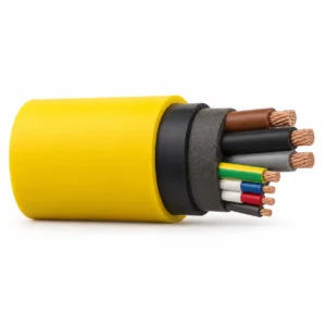
1-CBEH 0.6/1kV Gassy Mine Cable with Control and Monitoring Cores
A related cable option for a different application or duty profile.
View product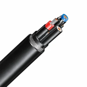
NTSKCGWÖU 0.6/1 (1.2) kV Mining Loader Cable
A related cable option for a different application or duty profile.
View product
MCP & MCPTJ Coal Cutter and Shearer Screened Flexible Cable (0.66/1.14–1.9/3.3 kV)
A related cable option for a different application or duty profile.
View productRequest a cable recommendation and quotation
Send the required services, cable length, mechanical duty, environment, termination and quantity. Our team will review the application before quoting.
- Include the product name or SKU plus the required cable length and quantity.
- Attach a specification, drawing or data sheet when available.