











8Y13 / 8Y26 Multilayer Insulated Transformer Wire
8Y13 / 8Y26 multilayer insulated transformer wire combines silver-plated copper with overlapping polyimide and FEP insulation for compact wound components. Choose the solid or stranded build, insulation system, AC duty and termination process for the transformer design.
8Y13 / 8Y26 multilayer insulated transformer wire is a thin-wall PI/FEP winding-wire family for transformers and other wound components. Silver-plated conductors and overlapping polyimide insulation provide compact electrical separation where winding space and a controlled insulation build are important. The two constructions retain separate conductor, voltage and bending data in the tables.
Choose 8Y13 when the winding specification calls for a solid conductor: the listed range extends from AWG 34/1 to AWG 11/1. Choose the 8Y26 stranded construction when the assembly needs a seven-wire or nineteen-wire conductor with two individually applied polyimide tape systems and a thin FEP finish. Conductor diameter and finished-wire diameter serve different design checks, so compare both against the winding window, bobbin and lead-out passage.
The insulation system must be selected with the complete transformer. A winding wire used for basic, supplementary or reinforced separation needs the matching winding arrangement, end preparation, creepage and clearance design. Thermal limits also depend on operating mode: the 8Y26 fixed-installation reference reaches 200 °C, while its fully flexible operating reference reaches 180 °C. The AC test voltage is a separate verification value from the operating voltage.
For a technical quotation, specify the exact designation and AWG construction, winding duty, required insulation system, finished diameter, colour, length and termination method. Include the transformer drawing and required component documentation so that the conductor build and insulation sequence can be matched to the assembly.
Explore the industrial cable range for related configurations.
For background on insulation systems and conductor finishes, read the high-temperature wire insulation guide alongside the separate winding-wire data above.
Construction
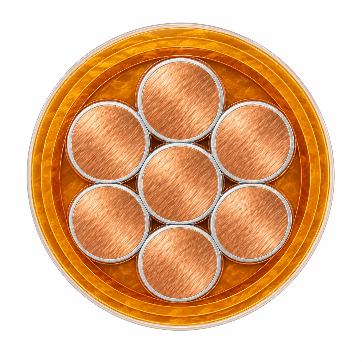
The representative 8Y26 AWG 22/7 construction is a single seven-wire silver-plated copper conductor with two polyimide tape systems, each shown with two layers, and a thin FEP top coat. The 8Y13 solid-wire construction is listed separately below.
| Component | Material and construction |
|---|---|
| 8Y13 conductor | Silver-coated high-strength copper alloy for AWG 34–28; silver-coated copper wire or strand for AWG 27–11. The size table on this page covers the listed solid /1 constructions. Silver coating is at least 1 µm. |
| 8Y13 multilayer insulation | 25.4 µm polyimide foil, coated on one side with 12.7 µm FEP and applied with at least 67% overlap. |
| 8Y26 conductor | Silver-plated Cu-ETP A021 or A022 to EN 13602, with silver coating of at least 1.02 µm according to ASTM B298. Seven-wire and nineteen-wire arrangements are listed by size. |
| 8Y26 first tape system | 0.031 mm polyimide HR616 foil with at least 52% overlap; two layers in the listed configurations. |
| 8Y26 second tape system | A separate 0.031 mm polyimide HR616 foil tape with at least 52% overlap; two layers in the listed configurations. |
| 8Y26 surface finish | Coloured FEP top coat with nominal thickness 0.02 mm. The thin insulation finish is part of the winding-wire build, rather than a separate heavy cable sheath. |
Applications
Select the wire with the transformer insulation system and winding process. The insulation build, conductor flexibility and lead-out routing all affect the final wound assembly.
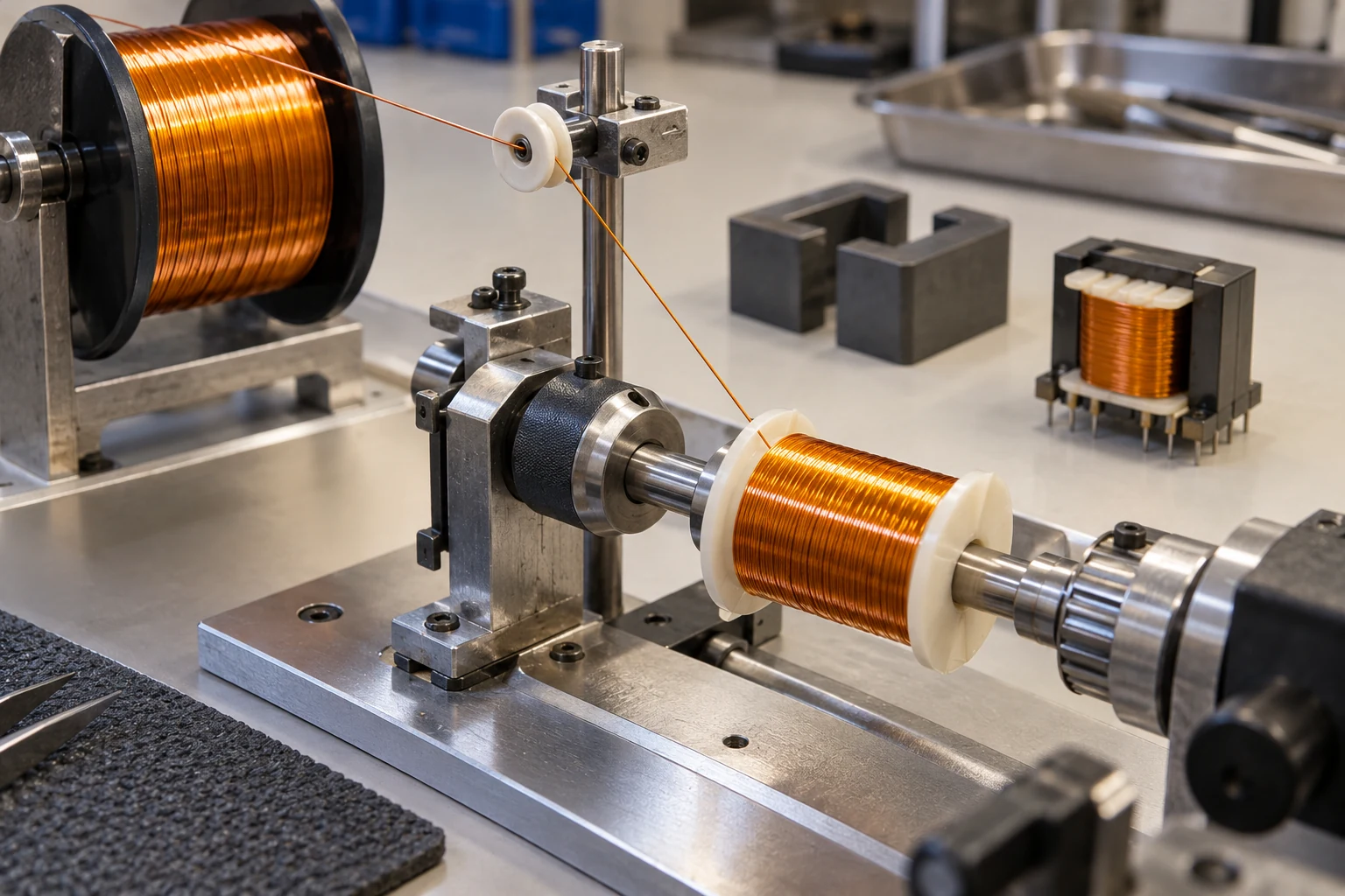
- Transformer windings requiring a multilayer-insulated conductor and a defined basic, supplementary or reinforced insulation arrangement.
- Compact wound components where finished-wire diameter must fit a limited bobbin window or winding space.
- 8Y13 solid-wire windings where the specified /1 conductor geometry and configuration-specific minimum bend radius can be maintained.
- 8Y26 stranded winding leads and assemblies requiring the documented seven-wire or nineteen-wire conductor build.
- Keep the overlapping insulation intact during winding, clamping and lead-out preparation; match stripping and termination methods to the PI/FEP system.
- Confirm the winding insulation system, end clearances, thermal duty and required component documentation before releasing the production drawing.
Specifications
| Parameter | Value |
|---|---|
| Construction family | Single-conductor multilayer PI/FEP insulated winding wire. |
| 8Y13 AC operating voltage | 0.6 kV. |
| 8Y26 AC operating voltage | 0.9 kV; 1 kV under the listed UL design conditions. |
| AC test voltage | 6 kV for both listed constructions. |
| Fixed-installation temperature | −55 °C to +200 °C. |
| 8Y26 fully flexible temperature | −55 °C to +180 °C. |
| 8Y13 bending | Configuration-specific minimum radii from 2 mm to 10.4 mm in the solid-wire table. |
| 8Y26 minimum bend radius | 2 × D, where D is the finished-wire outside diameter. |
| Size range | 8Y13: AWG 34/1–11/1; 8Y26: AWG 18/7–26/7 and AWG 26/19. |
| Model and conductor configuration | Nom. conductor diameter (mm) | Nom. cross-section (mm²) | Min. OD (mm) | Max. OD (mm) | Min. bend radius (mm) | Approx. mass (kg/km) |
|---|---|---|---|---|---|---|
| 8Y13 1 × AWG 34/1 | 0.16 | 0.02 | 0.4 | 0.5 | 2 | 0.36 |
| 8Y13 1 × AWG 33/1 | 0.18 | 0.026 | 0.39 | 0.49 | 2 | 0.37 |
| 8Y13 1 × AWG 32/1 | 0.203 | 0.032 | 0.42 | 0.52 | 2.1 | 0.5 |
| 8Y13 1 × AWG 31/1 | 0.226 | 0.04 | 0.46 | 0.55 | 2.2 | 0.59 |
| 8Y13 1 × AWG 30/1 | 0.254 | 0.051 | 0.45 | 0.55 | 2.2 | 0.75 |
| 8Y13 1 × AWG 29/1 | 0.287 | 0.065 | 0.49 | 0.59 | 2.4 | 0.85 |
| 8Y13 1 × AWG 28/1 | 0.32 | 0.08 | 0.53 | 0.63 | 2.5 | 1.05 |
| 8Y13 1 × AWG 27/1 | 0.361 | 0.102 | 0.57 | 0.67 | 2.7 | 1.24 |
| 8Y13 1 × AWG 26/1 | 0.404 | 0.128 | 0.6 | 0.7 | 2.8 | 1.5 |
| 8Y13 1 × AWG 25/1 | 0.455 | 0.162 | 0.68 | 0.78 | 3.1 | 1.85 |
| 8Y13 1 × AWG 24/1 | 0.511 | 0.205 | 0.7 | 0.8 | 3.2 | 2.25 |
| 8Y13 1 × AWG 23/1 | 0.574 | 0.259 | 0.81 | 0.91 | 3.6 | 2.8 |
| 8Y13 1 × AWG 22/1 | 0.643 | 0.332 | 0.87 | 0.97 | 3.9 | 3.5 |
| 8Y13 1 × AWG 21/1 | 0.724 | 0.412 | 0.93 | 1.03 | 4.1 | 4.23 |
| 8Y13 1 × AWG 20/1 | 0.813 | 0.519 | 1.02 | 1.12 | 4.5 | 5.25 |
| 8Y13 1 × AWG 19/1 | 0.912 | 0.653 | 1.11 | 1.21 | 4.8 | 6.51 |
| 8Y13 1 × AWG 18/1 | 1.03 | 0.823 | 1.22 | 1.32 | 5.3 | 8.1 |
| 8Y13 1 × AWG 17/1 | 1.15 | 1.04 | 1.28 | 1.48 | 5.9 | 10 |
| 8Y13 1 × AWG 16/1 | 1.29 | 1.31 | 1.42 | 1.62 | 6.5 | 12.5 |
| 8Y13 1 × AWG 15/1 | 1.45 | 1.65 | 1.6 | 1.8 | 7.2 | 15.75 |
| 8Y13 1 × AWG 14/1 | 1.628 | 2.08 | 1.76 | 1.96 | 7.8 | 19.7 |
| 8Y13 1 × AWG 13/1 | 1.83 | 2.63 | 1.95 | 2.15 | 8.6 | 24.5 |
| 8Y13 1 × AWG 12/1 | 2.05 | 3.3 | 2.2 | 2.35 | 9.4 | 30.8 |
| 8Y13 1 × AWG 11/1 | 2.3 | 4.15 | 2.4 | 2.6 | 10.4 | 38.1 |
| Gauge condition | Positive tolerance | Negative tolerance |
|---|---|---|
| > AWG 30 | +3% | −1% |
| < AWG 30 | +7.5 µm | −2.5 µm |
| Model and conductor configuration | Max. conductor diameter (mm) | Min. OD (mm) | Max. OD (mm) | Single-wire diameter (mm) | Number of wires | First tape layers | Second tape layers |
|---|---|---|---|---|---|---|---|
| 8Y26 1 × AWG 18/7 | 1.18 | 1.35 | 1.45 | 0.404 | 7 | 2 | 2 |
| 8Y26 1 × AWG 20/7 | 0.96 | 1.2 | 1.3 | 0.32 | 7 | 2 | 2 |
| 8Y26 1 × AWG 22/7 | 0.76 | 0.95 | 1.15 | 0.254 | 7 | 2 | 2 |
| 8Y26 1 × AWG 24/7 | 0.61 | 0.8 | 1 | 0.203 | 7 | 2 | 2 |
| 8Y26 1 × AWG 26/7 | 0.48 | 0.7 | 0.9 | 0.16 | 7 | 2 | 2 |
| 8Y26 1 × AWG 26/19 | 0.51 | 0.87 | 0.97 | 0.102 | 19 | 2 | 2 |
| Model and conductor configuration | Nom. cross-section (mm²) |
|---|---|
| 8Y26 1 × AWG 18/7 | 0.823 |
| 8Y26 1 × AWG 20/7 | 0.519 |
| 8Y26 1 × AWG 22/7 | 0.332 |
| 8Y26 1 × AWG 24/7 | 0.205 |
| 8Y26 1 × AWG 26/7 | 0.128 |
| Model and conductor configuration | Approx. mass (kg/km) |
|---|---|
| 8Y26 1 × AWG 22/7 | 4.2 |
| 8Y26 1 × AWG 24/7 | 2.7 |
| 8Y26 1 × AWG 26/7 | 2.1 |
OD means finished-wire outside diameter. Keep the conductor diameter, finished diameter and nominal copper cross-section as distinct ordering values.
The /1, /7 and /19 suffixes identify the listed solid, seven-wire and nineteen-wire conductor constructions. The same AWG number does not give the same finished diameter for every construction.
Apply the specified minimum bend radius to winding and lead-out details. The 8Y13 table gives absolute radii; the 8Y26 reference uses a multiple of finished diameter.
Specify the required operating voltage and insulation-system documentation with the transformer drawing. The 6 kV AC test reference is not an operating-voltage rating.
Standards
| Standard or specification | Application |
|---|---|
| EN 13602 | Cu-ETP A021/A022 conductor material reference for 8Y26. |
| ASTM B298 | Silver-coated copper conductor reference for the 8Y26 plating system. |
| EN 61558 / IEC 61558 | Transformer and wound-component safety reference for insulation-system selection. |
| IEC 60950-1 / EN 60950-1 | Legacy equipment-insulation design reference associated with the listed multilayer winding-wire constructions. |
| UL AWM Style 1950 / Style 5466 | Construction references for 8Y13 and 8Y26 respectively; specify the required AWM construction and documentation in the order. |
| UL 1446 | Electrical insulation-system reference named for the 8Y13 winding-wire design. |
Related cable options
Compare these cable options by service combination, movement, load, voltage and transmission requirement.
PTFE Hook Up Wire up to 250°C, 150–1000 V UL AWM Styles
A related cable option for a different application or duty profile.
View product
FEP Hook Up Wire 150–200°C, 300/600 V UL AWM Styles
A related cable option for a different application or duty profile.
View product
UL XLPE & XLPO Hook-Up Wire, 90°C to 150°C, 300–600 V
A related cable option for a different application or duty profile.
View productRequest a cable recommendation and quotation
Send the required services, cable length, mechanical duty, environment, termination and quantity. Our team will review the application before quoting.
- Include the product name or SKU plus the required cable length and quantity.
- Attach a specification, drawing or data sheet when available.