

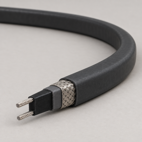
6 W/ft Self-Regulating Roof and Gutter Heating Cable, 120 V or 208–277 V
Self-regulating roof and gutter heat-trace construction with nominal 6 W/ft output at 40°F, available in 120 V and 208–277 V supply configurations.
This 6 W/ft self-regulating roof and gutter heating cable is intended to keep a drainage path open where ice can interrupt water movement from a roof edge through a gutter and downspout. The published output is 6 W/ft at 40°F (approximately 4.4°C); it is a measurement point, not a fixed heat output at every ambient temperature. Its conductive core adjusts local heat generation as conditions change. The same construction can be considered for freeze protection of water and drain pipes where the installation and control design allow it.
Two supply configurations serve different electrical layouts: 120 V, and 208–277 V AC. The latter is a voltage range, so circuit design must use the chosen supply voltage rather than assuming that all lengths or outputs are identical at 208 V, 240 V and 277 V. The reference data lists a 65°C maximum continuous maintenance temperature and an 85°C maximum intermittent exposure temperature. These are cable limits, not a promise that an uninsulated gutter or pipe will reach those temperatures.
For a useful quotation, identify the roof edge, gutter and downspout lengths, minimum design temperature, supply voltage, available breaker, controls and termination locations. Route the heat trace so meltwater can leave the building before it refreezes. This product serves de-icing and freeze protection; it should be specified separately from a constant-wattage silicone heater or a power-supply cable for a heating circuit.
Compare related constructions: high-temperature cable range. For a resistive heating element instead of self-regulating roof heat trace, compare the UL 3590 silicone heating wire.
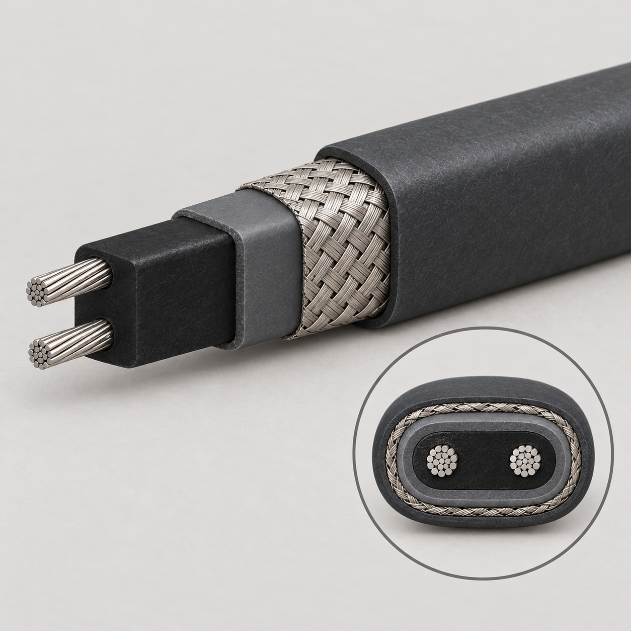
The reference construction has two 16 AWG nickel-coated copper bus wires embedded in an irradiation-crosslinked self-regulating conductive core. A modified-polyolefin inner jacket separates the core from a tinned-copper metallic braid; a modified-polyolefin outer jacket protects the assembly. This layered construction provides a continuous heating path along the installed length and a metallic overshield for the electrical design.
- Bus wires: 16 AWG nickel-coated copper.
- Heating element: irradiation-crosslinked self-regulating conductive core.
- Inner and outer jackets: modified polyolefin.
- Metallic overshield: tinned-copper braid.
Outer dimensions, jacket thickness, bus-wire spacing and minimum bend radius are not stated in the source sheet.
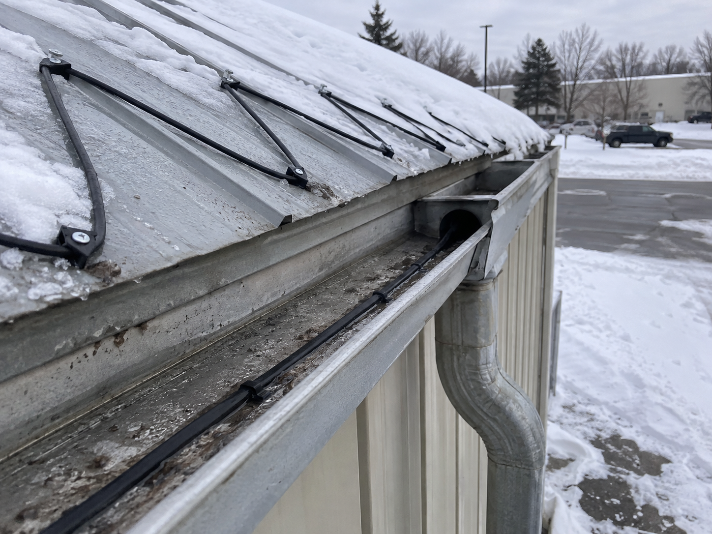
Use this roof and gutter heat trace to provide a meltwater path through roof edges, gutters and downspouts, and evaluate it for suitable water-pipe or drain-pipe freeze protection. A roof circuit must include the full drainage route: warming only the eave while leaving a cold downspout can still allow ice to block discharge.
- Residential or commercial roof and gutter de-icing.
- Freeze protection of water and drain piping where the installation design permits.
- Temperature maintenance within the documented cable exposure limits.
Specify the supply voltage, minimum design temperature, circuit length, control method and connection/termination components as one system.
Output is measured at the stated reference temperature. The temperature limits describe different operating conditions and are not interchangeable.
| Configuration | Output | Supply | Minimum installation temperature | Maximum powered temperature | Maximum unpowered exposure | Minimum bend radius |
|---|---|---|---|---|---|---|
| 6 W/ft self-regulating roof and gutter heating cable, 120 V AC | 6 W/ft at 40°F | 120 V AC | Not stated | 65°C | 85°C intermittent | Not stated |
| 6 W/ft self-regulating roof and gutter heating cable, 208–277 V AC | 6 W/ft at 40°F nominal; voltage-adjusted | 208–277 V AC | Not stated | 65°C | 85°C intermittent | Not stated |
The source gives 208 V and 277 V power-adjustment factors of 0.86 and 1.16, respectively, relative to its nominal high-voltage configuration. Confirm the selected voltage and circuit design before ordering. Maximum circuit length depends on the ordered voltage configuration, starting temperature and protective-device rating. Request the model-specific circuit-length schedule when planning the installation.
| Parameter | Source specification |
|---|---|
| Bus wires | 16 AWG nickel-coated copper |
| Self-regulating core | Irradiation-crosslinked conductive core |
| Inner jacket | Modified polyolefin |
| Metallic overshield | Tinned copper braid |
| Outer jacket | Modified polyolefin |
| 208 V output adjustment factor | 0.86 relative to nominal high-voltage configuration |
| 277 V output adjustment factor | 1.16 relative to nominal high-voltage configuration |
The selected cable, connection kit, protection device and controller must be documented for the destination installation. Specify the jurisdiction and roof/gutter or pipe application with the quotation so the final model marking and installation instructions can be supplied. The reference material describes an ordinary-location configuration; it does not provide a UL AWM Style number for this heating-cable family.
Related cable options
Compare these cable options by service combination, movement, load, voltage and transmission requirement.
230 V Self-Regulating Pipe and Tank Heat Trace Cable, 10–40 W/m
A related cable option for a different application or duty profile.
View product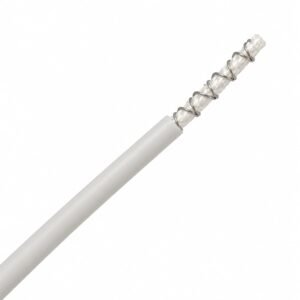
Silicone Rubber Heating Wire UL 3590, 200°C 300V
A related cable option for a different application or duty profile.
View productRequest a cable recommendation and quotation
Send the required services, cable length, mechanical duty, environment, termination and quantity. Our team will review the application before quoting.
- Include the product name or SKU plus the required cable length and quantity.
- Attach a specification, drawing or data sheet when available.