










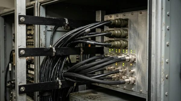


VG 95218 Naval Data, Bus, Coax & Hook-Up Cable
Complete naval shipboard high-speed data, fieldbus, RF coaxial, thermocouple compensating and switchboard hook-up cable portfolio built to German military standard VG 95218. Covers Part 31D Cat 7 S/FTP Ethernet, Part 31F/31X PROFIBUS DP, Part 31H CAN-Bus, Part 101 RG coaxial (50 Ω / 75 Ω), Part 7 Type D NiCr-Ni compensating cables, Part 20E/20P/21F hook-up wires and VG 95218-8 / -9 custom hybrid harnesses.
Naval combat management systems, bridge radar consoles, propulsion automation racks and weapon control cabinets require a unified, military-grade interconnection ecosystem where Ethernet backbones, real-time fieldbuses, RF coaxial feeds, thermocouple temperature loops and internal cabinet hook-up wires all comply with the German defence standard VG 95218 series.
For high-speed digital networks and machinery buses (−33 °C to +85 °C, 125 V), VG 95218 Part 31 provides four dedicated constructions: Part 31D Category 7 S/FTP 4-pair data cables (4 × 2 × 0.27 mm² and 4 × 2 × 0.355 mm² with aluminised pair foils and tinned copper braid, Zt ≤ 15–30 mΩ/m); Part 31F PROFIBUS DP cables (2 × 0.35 mm² white/brown cores); Part 31X hybrid PROFIBUS + 600/900 V power cables for mobile power units; and Part 31H CAN-Bus cables (2 × 0.34 mm² and 2 × 0.50 mm² red/green cores).
For RF communication, radar and navigation antennas (−40 °C to +105 °C), VG 95218 Part 101 covers halogen-free cross-linked coaxial cables across 50 ± 2 Ω (RG 58, RG 213, RG 214, RG 223) and 75 ± 2/3 Ω (RG 11, RG 59, RG 216). Exhaust gas and propulsion bearing monitoring use VG 95218-7 Type D screened NiCr-Ni (Type K) thermo-compensating cables (2 × 0.34 to 2 × 1.5 mm², 450 V, −40 °C to +90 °C).
Inside naval switchboards and electronics racks, VG 95218 Part 20E (0.15–10 mm²), Part 20P (0.15–150 mm²) and Part 21F open twisted hook-up wires operate from −55 °C to +105 °C at 600 V AC / 900 V DC with ≥ 75% smoke light transmittance. All elements can also be combined into custom hybrid cables under VG 95218-8 and VG 95218-9.
Explore the marine and offshore cable range for related configurations.
Construction
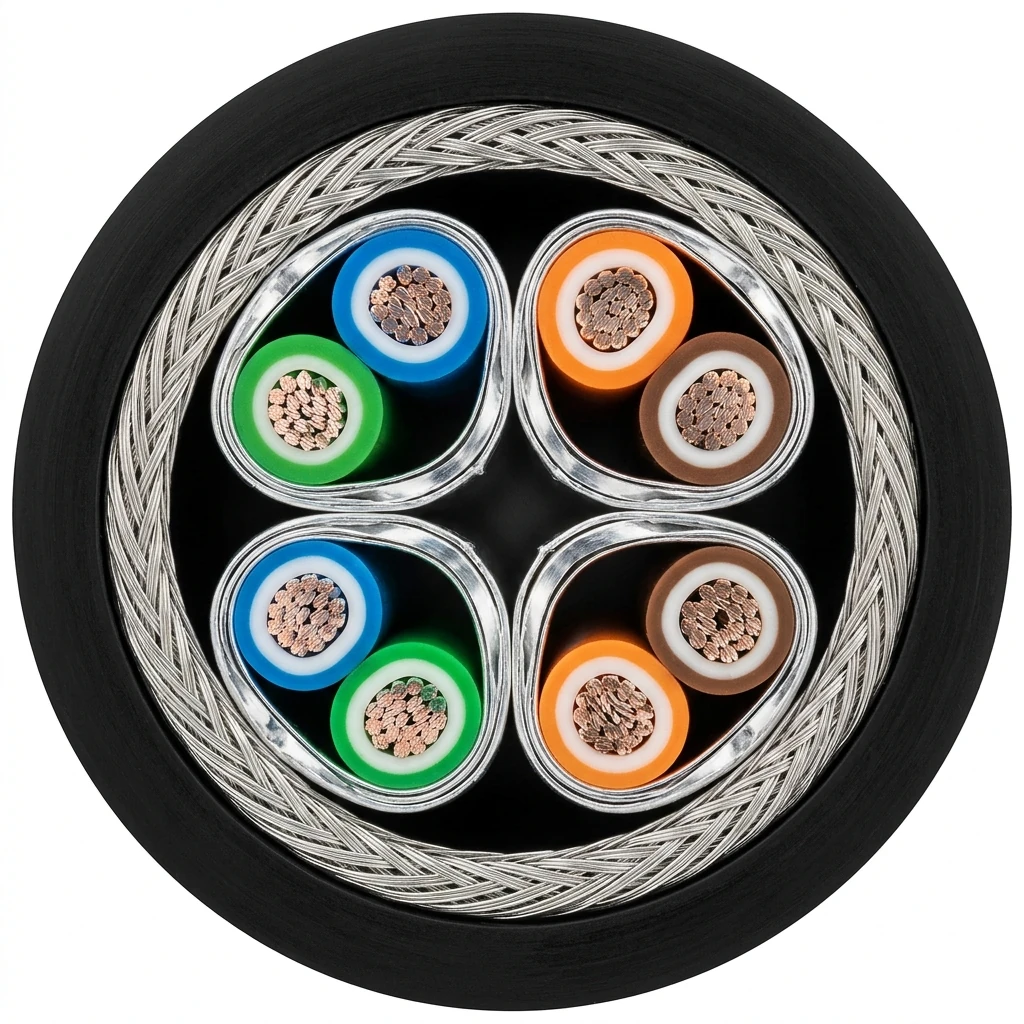
The representative cutaway showcases the VG 95218 naval data, fieldbus and RF coaxial family side by side: a 4-pair VG 95218-31D Cat 7 S/FTP data cable with individually foil-shielded pairs and tinned copper braid, a 1-pair VG 95218-31F/31H fieldbus cable, and a double-braided VG 95218-101 RG-214 coaxial cable.
| Component | Material and construction |
|---|---|
| Conductors | Fine-stranded tinned copper on Part 31 data/fieldbus and Part 20E/20P/21F hook-up wires; solid/stranded silvered or tinned copper on Part 101 coaxial cores; stranded NiCr-Ni thermocouple alloy on Part 7 Type D compensating cables. |
| Dielectric & Core Insulation | Special cross-linked halogen-free elastomer on Part 31D Cat 7 (WH/BU, WH/BN, WH/GN, WH/OR), Part 31F PROFIBUS (WH, BN), Part 31H CAN-Bus (RD, GN) and Part 20E/20P oil/chemical-resistant hook-up wires (11 colour codes 0–9 and G). |
| Pair & Element Shielding | Individual aluminised foil shield over each twisted pair on Part 31D Cat 7; plastic foil + tinned copper braid on Part 31F/31H; dual screen + inner covering on Part 31X hybrid PROFIBUS cable. |
| Overall EMC Braid Screen | Tinned copper wire braid screen achieving surface transfer impedance of 15–30 mΩ/m across Part 31 data/bus and Part 7D compensating cables, and precision 50 Ω / 75 Ω shielding on Part 101 RG coaxial cables. |
| Outer Sheath (VG 95218-8) | Black cross-linked, flame-retardant, halogen-free elastomer compliant with IEC 60332-1-2, IEC 60332-3-22 Cat. C, IEC 60754-1/-2 and IEC 61034 (≥ 75% light transparency on Part 20E/20P). |
Applications
Specify VG 95218-31, -101, -7D and -20/21 cables for fixed naval shipboard cabinets, combat system racks, mobile power units and custom VG 95218-9 harnesses.
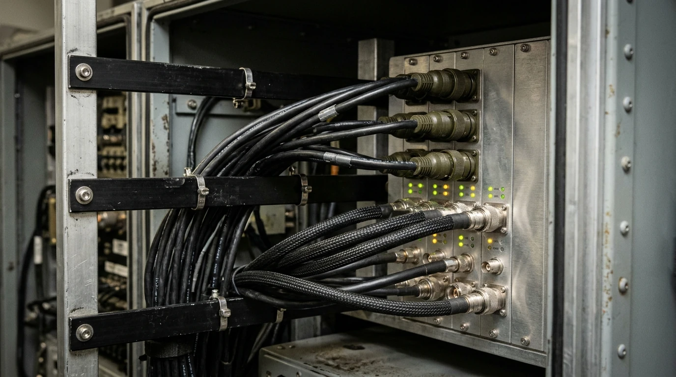
- 10GBASE-T combat management system (CMS), bridge radar and tactical LAN backbones using VG 95218 Part 31D Cat 7 S/FTP cables.
- Propulsion control, automated power management and mobile power unit interconnections using VG 95218 Part 31F/31X PROFIBUS DP and Part 31H CAN-Bus cables.
- Naval HF/VHF/UHF communications, GPS, AIS, radar and video distribution using VG 95218 Part 101 50 Ω (RG 58/213/214/223) and 75 Ω (RG 11/59/216) coaxial cables.
- Diesel engine exhaust, gas turbine and shaft-bearing Type K thermocouple extension circuits using VG 95218-7 Type D NiCr-Ni compensating cables.
- Internal rack, console and power distribution cabinet wiring from 0.15 mm² (AWG 26) up to 150 mm² using VG 95218 Part 20E, Part 20P and Part 21F hook-up wires, or bespoke multi-element harnesses built to VG 95218-8 / VG 95218-9.
Specifications
| Parameter | Value |
|---|---|
| Construction standards | Designed and manufactured to VG 95218 Part 31 (31D, 31F, 31H, 31X), Part 101, Part 7 Type D, Part 20 (20E, 20P), Part 21 (21F), Part 8 and Part 9. |
| Operating voltage ratings | Part 31D / 31F / 31H data and bus pairs: 125 V AC/DC; Part 31X hybrid power cores: 600/900 V; Part 7 Type D compensating cable: 450 V AC/DC; Part 20E / 20P / 21F hook-up wires: 600 V AC / 900 V DC. |
| Operating temperature ranges | Part 31D / 31F / 31H / 31X data and fieldbus: −33 °C to +85 °C; Part 7 Type D thermo-compensating: −40 °C to +90 °C; Part 101 RG coaxial: −40 °C to +105 °C; Part 20E / 20P / 21F hook-up wires: −55 °C to +105 °C. |
| EMC transfer impedance and RF impedance | Part 31D / 31F / 31H / 31X and Part 7D transfer impedance: max. 15–30 mΩ/m; Part 101 coaxial characteristic impedance: 50 ± 2 Ω (RG 58, 213, 214, 223) and 75 ± 2/3 Ω (RG 11, 59, 216). |
| Fire, smoke and halogen performance | Flame-retardant to IEC 60332-1-2 and IEC 60332-3-22 Cat. C; halogen-free and non-corrosive to IEC 60754-1 and IEC 60754-2; low smoke density to IEC 61034 (at least 75% light transparency on Part 20E/20P). |
| Hook-up wire colour code system | Standard VG 95218-20 colour suffixes: 0 = black, 1 = brown, 2 = red, 3 = orange, 4 = yellow, 5 = green, 6 = blue, 7 = violet, 8 = grey, 9 = white, G = yellow/green. |
| Custom hybrid capability (VG 95218-9) | Combines approved VG single cores (20L/20M/20P), twisted pairs (21F), screened elements (22G/23C/23G), fibre optics (30A/30B), Cat 7 (31D), PROFIBUS (31F), CAN (31H) and RG coax (101) under VG 95218-8 sheaths B, D, E, F, G or H. |
| VG standard & cable family | Type & formation | Max. core Ø (mm) | Min. sheath wall (mm) | Overall cable Ø min – max (mm) | Max. weight (kg/km) | Max. Zt (mΩ/m) | Operating voltage (V) | Temp. range | Standard VG part designation |
|---|---|---|---|---|---|---|---|---|---|
| VG 95218 Part 31D (Cat 7 Ethernet) | Cat 7 4 × 2 × 0.27 | 0.7 | 0.8 | 8.3 – 8.8 | 120 | 15 | 125 | −33 to +85 °C | VG 95218 T031D001 |
| VG 95218 Part 31D (Cat 7 Ethernet) | Cat 7 4 × 2 × 0.355 | 0.8 | 1.3 | 10.6 – 11.0 | 150 | 30 | 125 | −33 to +85 °C | VG 95218 T031D002 |
| VG 95218 Part 31X (PROFIBUS Hybrid) | Hybrid data + power cable | 2.25 (data) / 2.15 (power) | 1.5 | 15.4 – 16.2 | 396 | 30 | 125 (data) / 600/900 (power) | −33 to +85 °C | VG 95218T031X001 |
| VG 95218 Part 31F (PROFIBUS DP) | PROFIBUS 2 × 0.35 (3.1 mm core) | 3.1 | 1.3 | 9.6 – 10.0 | 110 | 15 | 125 | −33 to +85 °C | VG 95218 T031F001 |
| VG 95218 Part 31F (PROFIBUS DP) | PROFIBUS 2 × 0.35 (2.8 mm core) | 2.8 | 1.3 | 9.0 – 9.4 | 110 | 20 | 125 | −33 to +85 °C | VG 95218 T031F002 |
| VG 95218 Part 31H (CAN-Bus) | CAN-Bus 2 × 0.34 (2.18 mm core) | 2.18 | 1.3 | 7.6 – 8.0 | 90 | 15 | 125 | −33 to +85 °C | VG 95218 T031H001 |
| VG 95218 Part 31H (CAN-Bus) | CAN-Bus 2 × 0.34 (2.15 mm core) | 2.15 | 1.3 | 7.6 – 8.0 | 90 | 15 | 125 | −33 to +85 °C | VG 95218 T031H002 |
| VG 95218 Part 31H (CAN-Bus) | CAN-Bus 2 × 0.50 | 2.35 | 1.08 | 7.6 – 8.2 | 83 | 25 | 125 | −33 to +85 °C | VG 95218 T031H003 |
| VG 95218-7 Type D (NiCr-Ni Type K) | Thermo-compensating 2 × 0.34 | 0.8 | 0.8 | 4.9 – 5.3 | 42 | 30 | 450 | −40 to +90 °C | VG95218T007D001 |
| VG 95218-7 Type D (NiCr-Ni Type K) | Thermo-compensating 2 × 0.50 | 1.0 | 0.9 | 5.5 – 5.9 | 52 | 30 | 450 | −40 to +90 °C | VG95218T007D002 |
| VG 95218-7 Type D (NiCr-Ni Type K) | Thermo-compensating 2 × 0.75 | 1.2 | 1.0 | 5.9 – 6.3 | 62 | 30 | 450 | −40 to +90 °C | VG95218T007D003 |
| VG 95218-7 Type D (NiCr-Ni Type K) | Thermo-compensating 2 × 1.0 | 1.4 | 1.0 | 6.6 – 7.0 | 77 | 30 | 450 | −40 to +90 °C | VG95218T007D004 |
| VG 95218-7 Type D (NiCr-Ni Type K) | Thermo-compensating 2 × 1.5 | 1.7 | 1.1 | 7.2 – 7.6 | 93 | 30 | 450 | −40 to +90 °C | VG95218T007D005 |
| Coaxial type | Central conductor Ø (mm) | Min. sheath wall (mm) | Overall cable Ø min – max (mm) | Characteristic impedance | Max. weight (kg/km) | Operating temperature | Standard VG part designation |
|---|---|---|---|---|---|---|---|
| RG 11 | 1.2 | 1.1 | 10.1 – 10.5 | 75 ± 3 Ω | 180 | −40 to +105 °C | VG95218T101F001 |
| RG 58 | 0.9 | 0.7 | 4.8 – 5.1 | 50 ± 2 Ω | 50 | −40 to +105 °C | VG95218T101B001 |
| RG 59 | 0.6 | 0.8 | 6.0 – 6.3 | 75 ± 2 Ω | 80 | −40 to +105 °C | VG95218T101D001 |
| RG 213 | 2.25 | 1.1 | 10.1 – 10.5 | 50 ± 2 Ω | 175 | −40 to +105 °C | VG95218T101A002 |
| RG 214 | 2.25 | 1.0 | 10.6 – 11.0 | 50 ± 2 Ω | 220 | −40 to +105 °C | VG95218T101C002 |
| RG 216 | 1.2 | 1.0 | 10.6 – 11.0 | 75 ± 3 Ω | 210 | −40 to +105 °C | VG95218T101E001 |
| RG 223 | 0.9 | 0.6 | 5.25 – 5.55 | 50 ± 2 Ω | 66 | −40 to +105 °C | VG95218T101C001 |
| Nominal cross-section | Approx. AWG | VG 95218 Part 20E part no. range | VG 95218 Part 20P part no. range | Max. operating voltage | Operating temperature | Standard VG colour suffix codes |
|---|---|---|---|---|---|---|
| 0.15 mm² | AWG 26 | E120 … E129, E12G | P120 … P129, P12G | 600 V AC / 900 V DC | −55 to +105 °C | 0=BK, 1=BN, 2=RD, 3=OG, 4=YE, 5=GN, 6=BU, 7=VT, 8=GY, 9=WH, G=YE/GN |
| 0.25 mm² | AWG 24 | E010 … E019, E01G | P010 … P019, P01G | 600 V AC / 900 V DC | −55 to +105 °C | 0=BK, 1=BN, 2=RD, 3=OG, 4=YE, 5=GN, 6=BU, 7=VT, 8=GY, 9=WH, G=YE/GN |
| 0.40 mm² | AWG 22 | E020 … E029, E02G | P020 … P029, P02G | 600 V AC / 900 V DC | −55 to +105 °C | 0=BK, 1=BN, 2=RD, 3=OG, 4=YE, 5=GN, 6=BU, 7=VT, 8=GY, 9=WH, G=YE/GN |
| 0.50 mm² | AWG 21 | E030 … E039, E03G | P030 … P039, P03G | 600 V AC / 900 V DC | −55 to +105 °C | 0=BK, 1=BN, 2=RD, 3=OG, 4=YE, 5=GN, 6=BU, 7=VT, 8=GY, 9=WH, G=YE/GN |
| 0.60 mm² | AWG 20 | E040 … E049, E04G | P040 … P049, P04G | 600 V AC / 900 V DC | −55 to +105 °C | 0=BK, 1=BN, 2=RD, 3=OG, 4=YE, 5=GN, 6=BU, 7=VT, 8=GY, 9=WH, G=YE/GN |
| 0.75 mm² | AWG 19 | E050 … E059, E05G | P050 … P059, P05G | 600 V AC / 900 V DC | −55 to +105 °C | 0=BK, 1=BN, 2=RD, 3=OG, 4=YE, 5=GN, 6=BU, 7=VT, 8=GY, 9=WH, G=YE/GN |
| 1.0 mm² | AWG 18 | E060 … E069, E06G | P060 … P069, P06G | 600 V AC / 900 V DC | −55 to +105 °C | 0=BK, 1=BN, 2=RD, 3=OG, 4=YE, 5=GN, 6=BU, 7=VT, 8=GY, 9=WH, G=YE/GN |
| 1.2 mm² | AWG 16 | E070 … E079, E07G | P070 … P079, P07G | 600 V AC / 900 V DC | −55 to +105 °C | 0=BK, 1=BN, 2=RD, 3=OG, 4=YE, 5=GN, 6=BU, 7=VT, 8=GY, 9=WH, G=YE/GN |
| 1.5 mm² | AWG 15 | E080 … E089, E08G | P080 … P089, P08G | 600 V AC / 900 V DC | −55 to +105 °C | 0=BK, 1=BN, 2=RD, 3=OG, 4=YE, 5=GN, 6=BU, 7=VT, 8=GY, 9=WH, G=YE/GN |
| 2.0 mm² | AWG 14 | E090 … E099, E09G | P090 … P099, P09G | 600 V AC / 900 V DC | −55 to +105 °C | 0=BK, 1=BN, 2=RD, 3=OG, 4=YE, 5=GN, 6=BU, 7=VT, 8=GY, 9=WH, G=YE/GN |
| 2.5 mm² | AWG 13 | E100 … E109, E10G | P100 … P109, P10G | 600 V AC / 900 V DC | −55 to +105 °C | 0=BK, 1=BN, 2=RD, 3=OG, 4=YE, 5=GN, 6=BU, 7=VT, 8=GY, 9=WH, G=YE/GN |
| 3.0 mm² | AWG 12 | E110 … E119, E11G | P110 … P119, P11G | 600 V AC / 900 V DC | −55 to +105 °C | 0=BK, 1=BN, 2=RD, 3=OG, 4=YE, 5=GN, 6=BU, 7=VT, 8=GY, 9=WH, G=YE/GN |
| 4.0 mm² | AWG 12 | E130 … E139, E13G | P130 … P139, P13G | 600 V AC / 900 V DC | −55 to +105 °C | 0=BK, 1=BN, 2=RD, 3=OG, 4=YE, 5=GN, 6=BU, 7=VT, 8=GY, 9=WH, G=YE/GN |
| 6.0 mm² | AWG 10 | E140 … E149, E14G | P140 … P149, P14G | 600 V AC / 900 V DC | −55 to +105 °C | 0=BK, 1=BN, 2=RD, 3=OG, 4=YE, 5=GN, 6=BU, 7=VT, 8=GY, 9=WH, G=YE/GN |
| 10 mm² | AWG 8 | E150 … E159, E15G | P150 … P159, P15G | 600 V AC / 900 V DC | −55 to +105 °C | 0=BK, 1=BN, 2=RD, 3=OG, 4=YE, 5=GN, 6=BU, 7=VT, 8=GY, 9=WH, G=YE/GN |
| 16 mm² | AWG 6 | – | P160 … P169, P16G | 600 V AC / 900 V DC | −55 to +105 °C | 0=BK, 1=BN, 2=RD, 3=OG, 4=YE, 5=GN, 6=BU, 7=VT, 8=GY, 9=WH, G=YE/GN |
| 25 / 35 / 50 / 70 / 95 / 120 / 150 mm² | AWG 4 / 2 / – | – | P170…P17G (25), P180…P18G (35), P190…P19G (50), P200…P20G (70), P210…P21G (95), P220…P22G (120), P230…P23G (150) | 600 V AC / 900 V DC | −55 to +105 °C | Standard 0–9 and G colour suffixes (Part 21F open twisted wires also available) |
| VG 95218-8 sheath type | Permitted installation zone | Sheath material & fire properties | Base VG cable standard reference | Approved VG 95218-9 internal construction elements (*with or without element jacket) |
|---|---|---|---|---|
| Sheath Type B | All military applications except underwater | Cross-linked halogen-free, non-toxic, non-corrosive, flame-retardant | VG 95218-28 Types C and E | VG95218T020P, T021F, T022G, T023C, T023G, T030B*, T031D*, T031F*, T031H*, T101* |
| Sheath Type D | Inboard naval vessels | Cross-linked halogen-free, non-toxic, non-corrosive, flame-retardant | VG 95218-31 Types D, F and H | VG95218T020P, T021F, T022G, T023C, T023G, T030B*, T031D*, T031F*, T031H*, T101* |
| Sheath Type E | Inboard and outboard submarine/vessel applications | Cross-linked halogen-free, non-toxic, non-corrosive, flame-retardant | VG 95218-29 Types B to F | VG95218T020L (single core), T020M (water-blocked single core), T020P, T021F, T022G, T023C, T023G, T030B*, T031D*, T031F*, T031H*, T101* |
| Sheath Type F | Outboard submarine / underwater vessels | Flame-retardant, halogen-free polyurethane (PUR) | VG 95218-29 Types G to M | VG95218T020L (single core) and VG95218T020M (water-blocked single core) |
| Sheath Type G | All military applications except underwater | Cross-linked halogen-free, non-toxic, non-corrosive, flame-retardant | VG 95218-30 Types A and B (fibre-optic) | VG95218T030A (breakout fibre optic) and VG95218T030B (bundle fibre optic) |
| Sheath Type H | Fixed and portable military installation | Cross-linked halogen-free, non-toxic, non-corrosive, flame-retardant | VG 95218-31 Type L | VG95218T030H (CAN-Bus element) |
Cables and hook-up wires are designed and manufactured to VG 95218 Parts 31, 101, 7D, 20E, 20P, 21F, 8 and 9 construction specifications; confirm project-specific BAAINBw / QSTAG release requirements during RFQ.
Note on Catalog p. 10 table header: the printed table sub-header above the VG 95218-7 Type D thermo-compensating rows reads "acc. to VG 95218 Part 31D" due to a source catalog typesetting carry-over from p. 9, whereas the page title and part numbers (VG95218T007D001 to T007D005) belong to VG 95218-7 Type D.
Beyond standard VG 95218-9 elements, custom non-VG naval hybrid cables can integrate single wires up to 1.5 kV AC, twisted pairs up to 1.0 kV AC, Cat 7 Ethernet, fieldbus, fibre-optic elements, fluid/gas hoses, magnetic screens, armour and 100 bar water-blocking.
Standards
| Standard or specification | Application |
|---|---|
| VG 95218 Part 31 (31D, 31F, 31H, 31X) | German defence standard for naval Category 7 Ethernet data cables, PROFIBUS DP fieldbus cables (including hybrid power/bus) and CAN-Bus cables. |
| VG 95218 Part 101 | German defence standard for halogen-free naval 50 Ω and 75 Ω RF coaxial cables (RG 11, 58, 59, 213, 214, 216, 223). |
| VG 95218 Part 7 Type D | Screened NiCr-Ni (Type K) thermocouple compensating cables (0.34–1.5 mm², 450 V) for naval propulsion and exhaust temperature instrumentation. |
| VG 95218 Parts 20E, 20P & 21F | Halogen-free, oil- and chemical-resistant single-core and open-twisted naval cabinet hook-up wires (600 V AC / 900 V DC, −55 °C to +105 °C). |
| VG 95218 Parts 8 & 9 | Sheath material classification (Types B, D, E, F, G, H) and modular element rules for custom-designed naval hybrid installation cables. |
DIN Media — VG 95218 Parts 7, 8, 9, 20, 21, 31 & 101 military cable standards
Related cable options
Compare these cable options by service combination, movement, load, voltage and transmission requirement.

VG 95218-28 Lightweight Naval Shipboard Cable
A related cable option for a different application or duty profile.
View product
Halogen-Free Cat5e–Cat7 Marine Ethernet Cable
A related cable option for a different application or duty profile.
View product
Halogen-Free Shipboard Marine Fieldbus Cable
A related cable option for a different application or duty profile.
View productRequest a cable recommendation and quotation
Send the required services, cable length, mechanical duty, environment, termination and quantity. Our team will review the application before quoting.
- Include the product name or SKU plus the required cable length and quantity.
- Attach a specification, drawing or data sheet when available.