

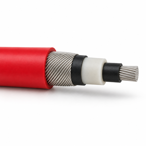
(N)TMCGC11Y Screened Single-Core MV Switchgear Cable
(N)TMCGC11Y screened single-core MV cable for short switchgear and transformer links: Class 5 tinned copper, EPR insulation, tinned-copper wire screen and red PUR sheath. Source rating family 3.6/6–18/30 kV; detailed 6/10 and 12/20 kV tables below.
(N)TMCGC11Y is a screened single-core medium-voltage cable for short connections in switchgear or transformer rooms where terminal space and the route’s bend radius need close attention. The supplied construction uses a finely stranded Class 5 tinned-copper main conductor, EPR insulation between semiconductive stress-control layers, spirally applied tinned-copper protective wires and a red PUR outer sheath. Its source catalogue lists a 3.6/6 to 18/30 kV voltage family and gives complete size data specifically for 6/10 and 12/20 kV.
Start selection with the circuit voltage and conductor/protective-wire size, then check the available enclosure space against the listed outer-diameter band. The source distinguishes a fixed route from free movement: their bending radii and ambient limits differ. The quoted current table has its own free-air reference arrangement, so the circuit rating must be recalculated for the real installation. Confirm the screen and earthing arrangement, termination dimensions and project standard before ordering.
The similar-looking (N)TMCGCW11Y crane cable has a different published construction and movement application; choose by the exact designation and drawing. Browse the industrial cable range for adjacent power designs. See the Specifications tab for the source-backed size matrix.
Construction
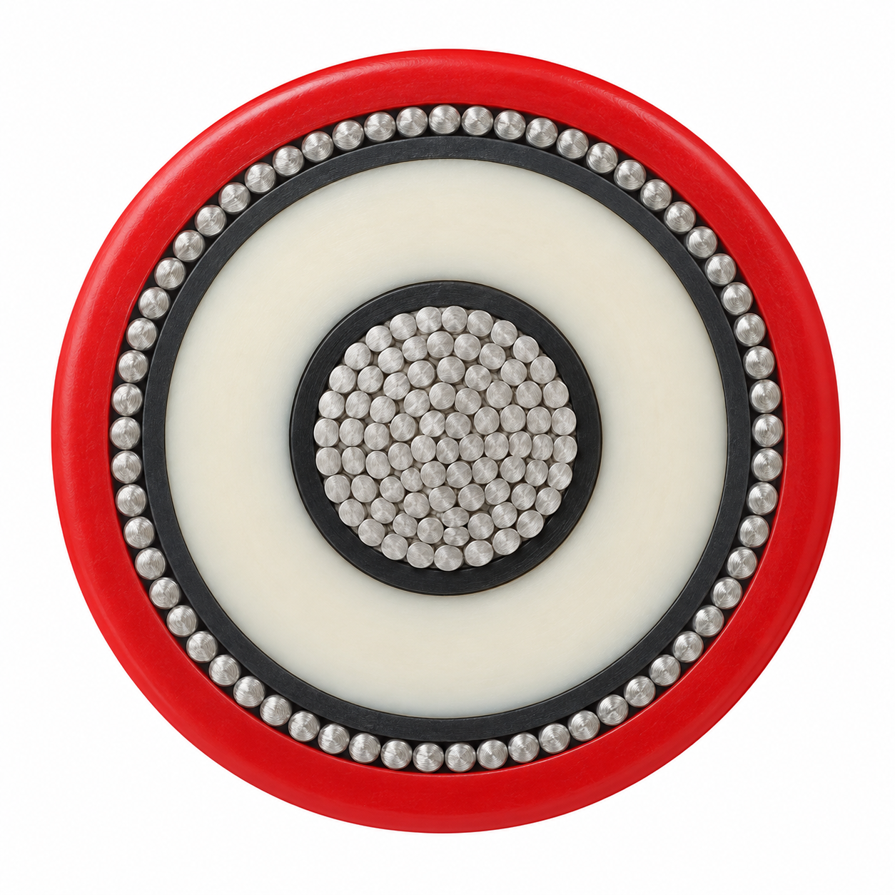
The (N)TMCGC11Y construction combines a tinned-copper conductor, semiconductive field-control layers, EPR insulation and protective copper wires. The tinned-copper protective wires are a separate specified layer; confirm the required protective-conductor and screen termination design on the project drawing.
| Layer | Source construction |
|---|---|
| Main conductor | Finely stranded Class 5 tinned copper, DIN EN/IEC 60228 reference |
| Inner stress-control layer | Extruded semiconductive layer |
| Insulation | EPR compound, DIN VDE 0207-20-based source description |
| Outer insulation screen | Semiconductive insulation-shield layer |
| Protective conductor | Spirally applied tinned-copper wires |
| Outer sheath | Red PUR compound; source lists oil, ozone, UV and moisture resistance |
Applications
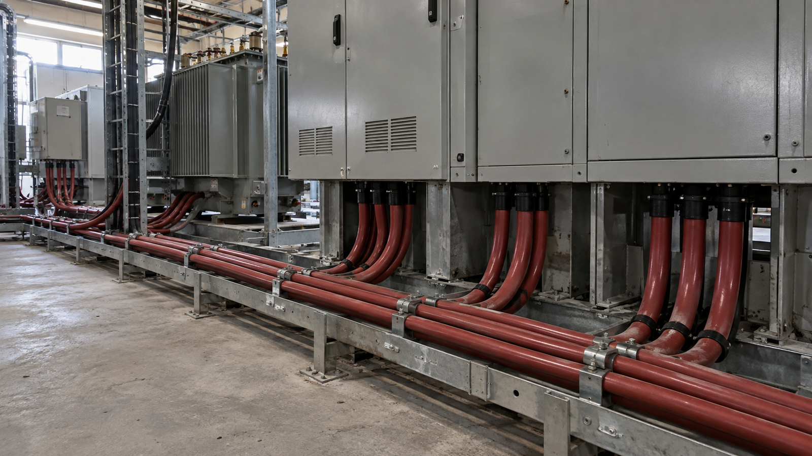
Use the (N)TMCGC11Y construction as a candidate for short MV links between switchgear and transformers, especially where the connection route has constrained bending space. Check whether the installed route is fixed or experiences movement; the source gives different temperature and bend values for those duties.
- Switchgear bay and transformer-house links after voltage, current and screen-bonding review.
- Industrial indoor or outdoor routes where the specified red PUR sheath and environmental requirements match the actual duty.
- Compare the (N)TMCGCW11Y cable where the application is a crane or other moving-equipment connection.
For a quote, specify U₀/U, main conductor/protective-wire section, length, movement duty, installation layout and termination arrangement.
Specifications
(N)TMCGC11Y catalogue reference ratings cover 3.6/6–18/30 kV. The supplied size tables cover 6/10 and 12/20 kV only. Do not assume that a size in those two tables is available at every other voltage.
| U₀/U kV | Max AC operating U₀/U kV | Max DC operating U₀/U kV | AC test kV |
|---|---|---|---|
| 3.6/6 | 4.2/7.2 | 5.4/10.8 | 11 |
| 6/10 | 6.9/12 | 9/18 | 17 |
| 8.7/15 | 10.4/18 | 13.5/27 | 24 |
| 12/20 | 13.9/24 | 18/36 | 29 |
| 14/25 | 17.3/30 | 22.5/45 | 36 |
| 18/30 | 20.8/36 | 27/54 | 43 |
| Parameter | Source value |
|---|---|
| Fixed ambient | −40 to +90 °C |
| Flexible operation ambient | −35 to +80 °C |
| Max conductor | 90 °C |
| Short circuit conductor | 250 °C |
| Tensile load | 15 N/mm² of conductor |
| Fixed bend | ≥6 × OD |
| Free-moving bend | ≥10 × OD |
(N)TMCGC11Y 6/10 kV catalogue size reference
| Model + size | Max conductor Ω/km | Nominal insulation OD mm | Cable OD mm | Approx. kg/km | Reference ampacity A |
|---|---|---|---|---|---|
| (N)TMCGC11Y 1 × 25/16 mm² 6/10 kV | 0.795 | 14.5 | 21–23 | 730 | 135 |
| (N)TMCGC11Y 1 × 35/16 mm² 6/10 kV | 0.565 | 16.0 | 22–24 | 860 | 169 |
| (N)TMCGC11Y 1 × 50/16 mm² 6/10 kV | 0.393 | 17.0 | 24–26 | 1045 | 207 |
| (N)TMCGC11Y 1 × 70/16 mm² 6/10 kV | 0.277 | 19.0 | 26–28 | 1290 | 268 |
| (N)TMCGC11Y 1 × 95/16 mm² 6/10 kV | 0.210 | 20.5 | 27–29 | 1545 | 328 |
| (N)TMCGC11Y 1 × 120/16 mm² 6/10 kV | 0.164 | 22.0 | 29–31 | 1820 | 383 |
| (N)TMCGC11Y 1 × 150/25 mm² 6/10 kV | 0.132 | 24.0 | 31–33 | 2170 | 444 |
| (N)TMCGC11Y 1 × 185/25 mm² 6/10 kV | 0.108 | 26.0 | 33–35 | 2515 | 510 |
| (N)TMCGC11Y 1 × 240/25 mm² 6/10 kV | 0.0817 | 28.0 | 36–38 | 3085 | 607 |
(N)TMCGC11Y 12/20 kV catalogue size reference
| Model + size | Max conductor Ω/km | Nominal insulation OD mm | Cable OD mm | Approx. kg/km | Reference ampacity A |
|---|---|---|---|---|---|
| (N)TMCGC11Y 1 × 25/16 mm² 12/20 kV | 0.795 | 18.0 | 25–27 | 925 | 135 |
| (N)TMCGC11Y 1 × 35/16 mm² 12/20 kV | 0.565 | 19.0 | 26–28 | 1065 | 169 |
| (N)TMCGC11Y 1 × 50/16 mm² 12/20 kV | 0.393 | 20.5 | 27–29 | 1250 | 207 |
| (N)TMCGC11Y 1 × 70/16 mm² 12/20 kV | 0.277 | 22.0 | 29–31 | 1520 | 268 |
| (N)TMCGC11Y 1 × 95/16 mm² 12/20 kV | 0.210 | 24.0 | 31–33 | 1790 | 328 |
| (N)TMCGC11Y 1 × 120/16 mm² 12/20 kV | 0.164 | 25.5 | 33–35 | 2075 | 383 |
| (N)TMCGC11Y 1 × 150/25 mm² 12/20 kV | 0.132 | 27.5 | 35–37 | 2455 | 444 |
| (N)TMCGC11Y 1 × 185/25 mm² 12/20 kV | 0.108 | 29.5 | 37–39 | 2815 | 510 |
| (N)TMCGC11Y 1 × 240/25 mm² 12/20 kV | 0.0817 | 31.5 | 39–41 | 3350 | 607 |
Reference current figures use conductor 90 °C, ambient 30 °C, free air, IEC 60364-5-52 installation method F, three loaded conductors in trefoil. Confirm derating, bonding and earth-fault duty for the actual circuit. Conductor resistance is shown in Ω/km at 20 °C.
Standards
Design references for (N)TMCGC11Y include DIN VDE 0250-813 and DIN EN/IEC 60228 for the Class 5 copper conductor, DIN VDE 0207-20 for the EPR compound, DIN VDE 0298-4 for derating, DIN EN/IEC 60811-404 for oil-resistance testing and DIN EN/IEC 60332-1-2 for single-cable flame behaviour. AC test voltages for each rated-voltage grade appear in Specifications.
Specify the applicable project edition, acceptance tests, terminal system and delivered documentation with the final construction drawing.
Related cable options
Compare these cable options by service combination, movement, load, voltage and transmission requirement.
(N)TMCGCW11Y Cable – Screened MV Crane Cable
A related cable option for a different application or duty profile.
View product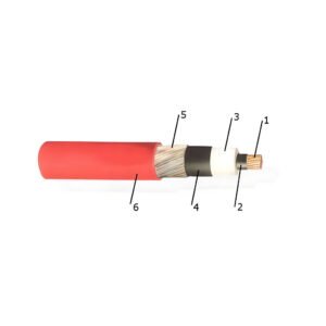
NTMCWOEU 26/45 kV Flexible Switchgear Cable
A related cable option for a different application or duty profile.
View productRequest a cable recommendation and quotation
Send the required services, cable length, mechanical duty, environment, termination and quantity. Our team will review the application before quoting.
- Include the product name or SKU plus the required cable length and quantity.
- Attach a specification, drawing or data sheet when available.