










(N)3GRDGC5G 0.6/1 kV EMC-Screened Round Rubber Crane Festoon Cable
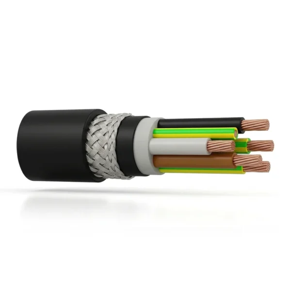
(N)3GRDGC5G (also specified as N3GRDGC5G and (N)3GRDGC5G-J/O) is a heavy-duty 0.6/1 kV EMC-screened round rubber festoon and crane power cable engineered in accordance with DIN VDE 0250-812 / DIN VDE 0250-813. Combining Class 5 flexible copper conductors, +90 °C EPR/HEPR core insulation (3GI3), a pressure-extruded inner elastomer sheath, an overall tinned-copper braided EMC screen (≥ 80%–85% optical coverage), and a wear-resistant black polychloroprene outer sheath (5GM5 / EM7), it delivers low-transfer-impedance power and control transmission on motorized crane festoon systems running at travel speeds up to 240–250 m/min.
- Rated Voltage: 0.6/1 kV (max. permitted operating voltage 0.7/1.2 kV AC, 0.9/1.8 kV DC; 2.5 kV AC test voltage)
- Conductor: Flexible Class 5 bare or tinned electrolytic copper per IEC 60228 / DIN VDE 0295
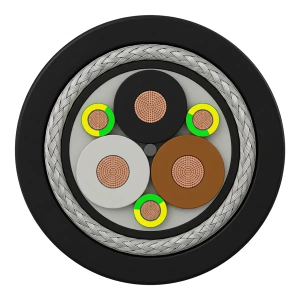
- Core Insulation & Earth Layout: Heat-resistant EPR / HEPR rubber compound (3GI3, +90 °C continuous / +250 °C short-circuit); 4-core/5-core up to 10 mm² and 3-phase + 3 symmetrical split earth cores from 16 mm²
- Inner Sheath: Pressure-extruded synthetic rubber compound (EM6) stabilizing core lay geometry under rapid cyclic bending
- EMC Shielding: Overall braided screen of tinned copper wires and synthetic threads (≥ 80% to 85% coverage) for VFD / inverter motor drives
- Outer Sheath: Heavy-duty black polychloroprene (PCP / CR) compound 5GM5 / EM7 — oil-resistant, UV/ozone-resistant, silicone-free, and flame-retardant
- Temperature Range: -35 °C to +80 °C dynamic flexing (-25 °C to +80 °C standard mobile); -40 °C to +80 °C (-50 °C fixed structural installation)
- Dynamic Festoon Duty & Standards: Travel speeds up to 240–250 m/min; tensile load 15 N/mm² static / up to 30 N/mm² dynamic per DIN VDE 0250-812/813 and DIN VDE 0298-3
Send your core configuration (e.g., 4 G 6C, 3 × 35 + 3 × 16/3, or 3 × 50 + 3G10C), festoon loop depth, trolley speed, and required length to receive a factory engineering quotation.
(N)3GRDGC5G 0.6/1 kV EMC-Screened Round Rubber Festoon Cable Overview
(N)3GRDGC5G (also specified as N3GRDGC5G or (N)3GRDGC5G-J/O) is a 0.6/1 kV EMC-screened round rubber cable engineered for high-speed motorized festoon systems, ship-to-shore (STS) and RMG container cranes, steelworks cranes, and carrier chains. In the DIN VDE 0250-812 / 0250-813 designation, (N) marks standard alignment, 3G specifies +90 °C EPR/HEPR insulation, RD denotes round festoon stranding, G is the pressure-extruded inner rubber sheath, C is the tinned-copper braided EMC screen, and 5G is the black 5GM5/EM7 polychloroprene outer sheath.
To reduce outer diameter and common-mode shaft currents on VFD crane drives, power sizes from 16 mm² upward use three main phase cores plus three symmetrical green/yellow split earth cores in the outer interstices (such as 3 × 35 + 3 × 16/3 or 3 × 35 + 3G6C), while smaller sizes use 4-core or 5-core layer stranding.
- Suitable for: Motorized I-beam and girder festoon trolleys at 210–250 m/min, VFD hoist/trolley motor feeders, and outdoor marine or steelworks festoons down to -35 °C.
- Confirm before ordering: Core and split-earth layout, outer diameter for festoon saddles and 360° EMC glands, travel speed, and tensile load (15 N/mm² static; 30 N/mm² dynamic).
- Choose another construction when: You need flat festoon stacking ((N)GFLCGÖU-J/O), high-tension monospiral drum reeling ((N)SHTÖU-J / (N)12YRDC11Y), or medium-voltage 3.6/6–20 kV crane feeders ((N)TSCGEWÖU).
For related VDE-standard crane festoon cables in our Port & Festoon Cables range, compare these screened constructions: (N)GRDGCGOEU-J 0.6/1 kV Screened Festoon Cable (for standard 0.6/1 kV EPR/PCP braided-screen round festoon loops up to 95 mm²); (N)GFLCGÖU-J/O 0.6/1 kV Screened Rubber Flat Festoon & Reeling Cable (for flat-stacked C-rail and I-beam festoon packs with individually or overall screened cores). Confirm trolley saddle profile, split-earth cross-section, and VFD gland bonding before ordering.
The (N)3GRDGC5G cable construction is engineered to prevent core corkscrewing, sheath delamination, and electromagnetic radiation during continuous high-speed festoon cycling. By extruding a pressure-filled inner synthetic rubber sheath directly over the short-pitch laid-up cores and interlinking it with the outer 5GM5 polychloroprene sheath across the tinned-copper EMC braid, the cable achieves high axial stability while remaining supple through tight catenary loops.
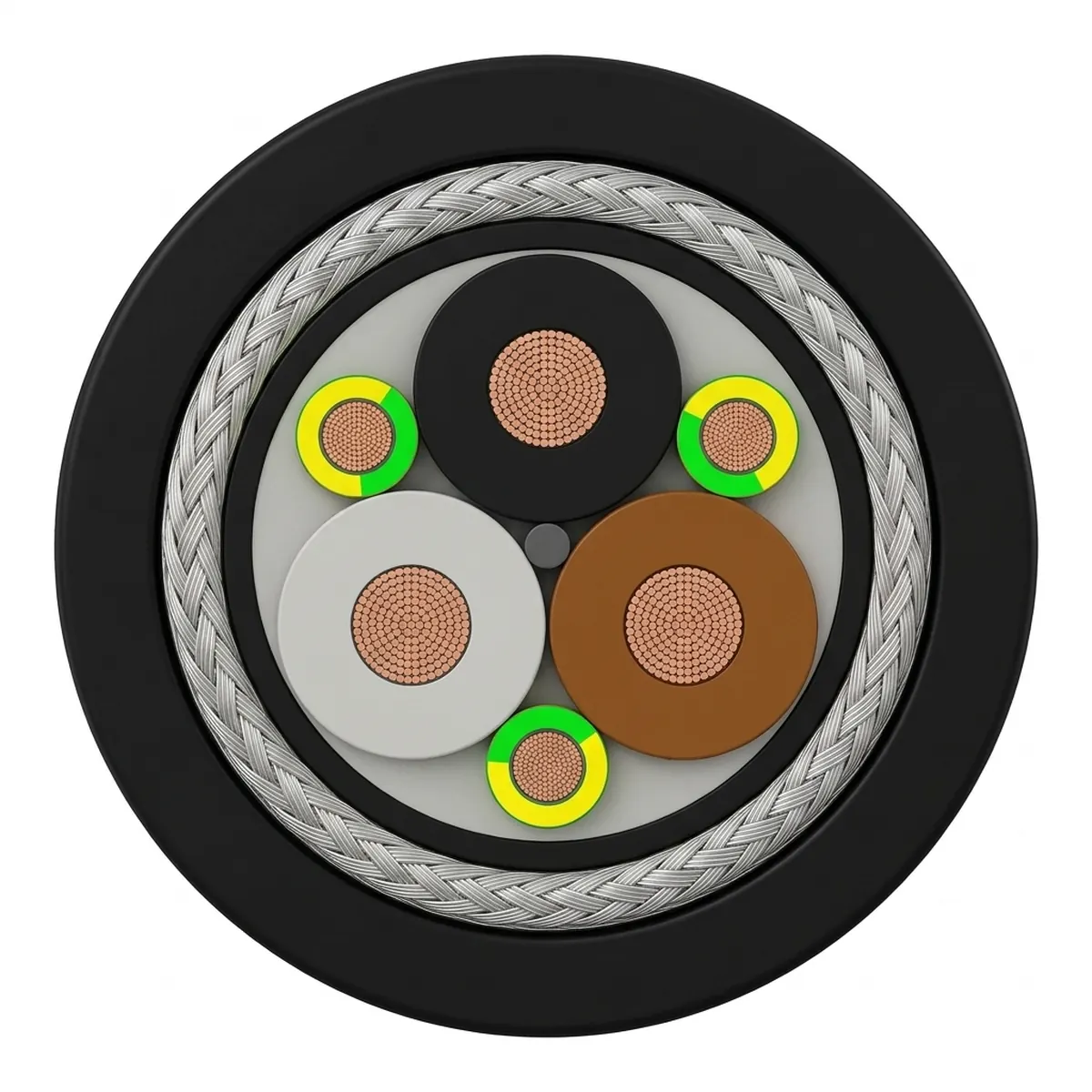
| Layer / Element | VDE Code | Material & Technical Specification | Engineering Function in Festoon Duty |
|---|---|---|---|
| 1. Flexible Conductor | — | Fine-stranded bare or tinned electrolytic copper, Class 5 (or finer FSC stranding) per IEC 60228 / DIN VDE 0295 | Absorbs millions of alternating bending cycles in festoon catenary loops and motorized trolley saddles without strand fatigue |
| 2. Core Insulation | 3G | High-grade Ethylene Propylene Rubber (EPR / HEPR compound 3GI3 per VDE 0207 / EN 50363-1), rated +90 °C continuous and +250 °C short-circuit | Provides high dielectric strength (0.6/1 kV, up to 0.7/1.2 kV AC), low dielectric loss under VFD pulse-width modulation (PWM) spikes, and flexibility down to -35 °C |
| 3. Core Identification & Symmetrical Split Earth | RD / -J / -O | Up to 10 mm²: 4 or 5 cores laid up in short-pitch concentric layers. From 16 mm² upward: 3 main phase cores plus 3 symmetrical green/yellow split protective-earth (PE) cores in the outer interstices (3 × Phase + 3 × PE/3 or 3 × Phase + 3G...C) | Reduces overall cable diameter by 10%–15% compared with 4-equal-core geometry, balances phase-to-earth capacitance on VFD motor drives, and maintains a circular core profile |
| 4. Inner Sheath / Pressure Bedding | G | Pressure-extruded synthetic rubber compound (EM6 per EN 50363-2-1), filling all core interstices | Locks the stranded core bundle against internal core migration, longitudinal shifting, and torsional corkscrewing at travel speeds up to 240–250 m/min |
| 5. Overall EMC Braided Screen | C | Concentric braid of tinned copper wires (or composite tinned-copper wire and synthetic-thread braid) with ≥ 80% to 85% optical coverage | Provides low transfer impedance and 360° electromagnetic shielding to contain VFD harmonic emissions and protect adjacent crane encoders, bus lines, and control circuits |
| 6. Heavy-Duty Outer Sheath | 5G | Wear-resistant black polychloroprene (PCP / CR) elastomer compound 5GM5 / EM7, silicone-free (LBS-free) | Resists oil (DIN EN 60811-2-1), UV radiation, coastal ozone, salt mist, sulfur, and mechanical abrasion in outdoor port and steelworks environments; flame-retardant per IEC 60332-1-2 |
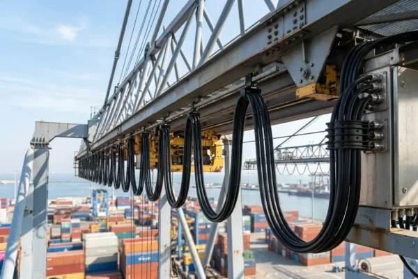
(N)3GRDGC5G 0.6/1 kV cables are built for continuous heavy-duty dynamic operation where high trolley travel speeds, rapid horizontal acceleration, outdoor atmospheric exposure, and strict electromagnetic compatibility (EMC) requirements coincide. Their pressure-filled round rubber profile resists wind-induced loop twisting on coastal container cranes while isolating sensitive crane control networks from high-power AC frequency-converter motor feeders.
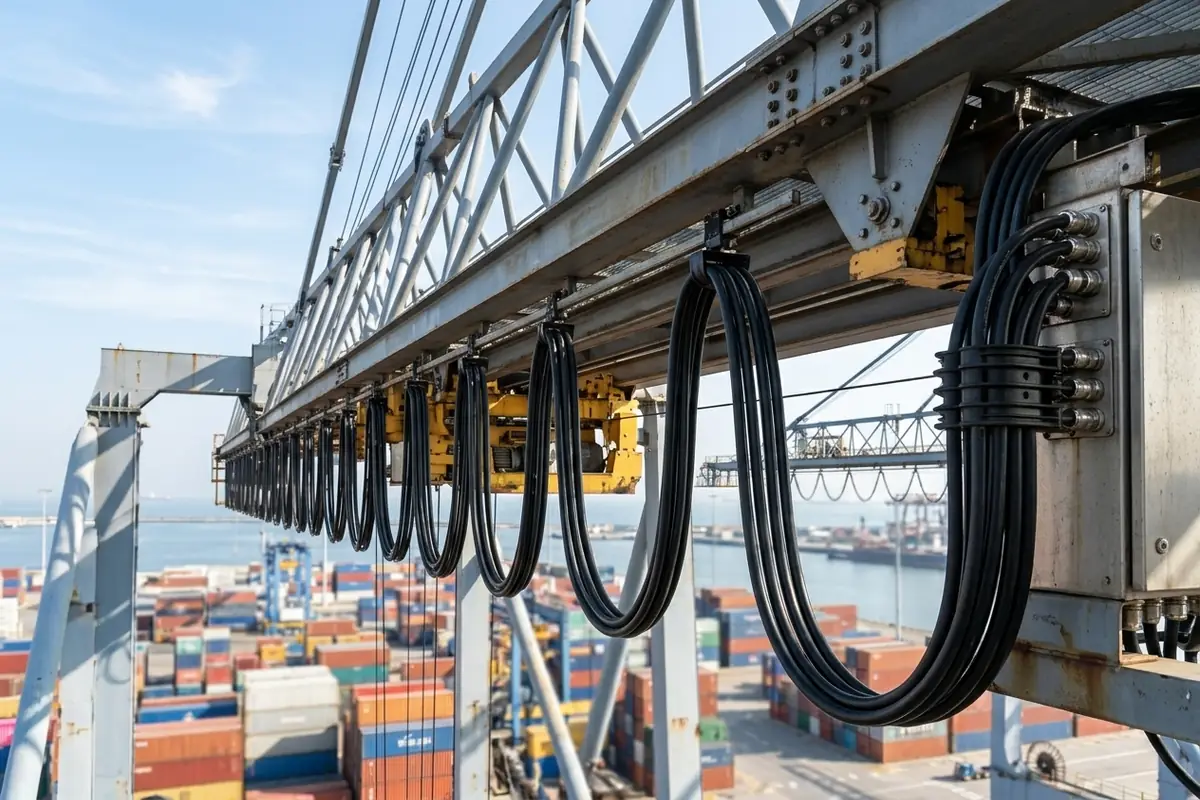
Primary Crane, Port & Heavy Industrial Applications
- Ship-to-Shore (STS) & RMG/RTG Container Crane Trolleys: Main boom and girder motorized festoon systems supplying VFD-driven hoist, trolley, and boom-hoist motors at travel speeds from 210 m/min up to 240–250 m/min.
- Steelworks, Foundry & Process Crane Festoons: Heavy-duty indoor and outdoor overhead bridge cranes, ladle handling cranes, and coil-yard gantries exposed to radiant heat, metallic dust, oil mist, and sulfur-bearing atmospheres.
- Bulk Material Handling & Port Unloaders: Festoon loops and guided power loops on bucket-wheel stacker-reclaimers, ship unloaders, railcar dumpers, and heavy conveyor transfer cars.
- Automated Transport Carriers & Heavy Energy Chains: Horizontal drag-chain and towed trolley installations requiring a rugged 0.6/1 kV screened round elastomer cable with torsional stability up to ±90 °/m.
- Screened Control & Bus/Data Festoon Loops: Multi-pair screened configurations (such as 6 × (2 × 0.5)C, 6 × (2 × 1.0)C, and 9 × (2 × 1.0)C) running alongside power festoon loops without signal cross-talk.
Festoon Saddle Clamping & EMC Installation Guidelines
- Saddle Diameter Matching: Group round cables of similar outer diameter within the same festoon saddle window; if adjacent cable diameters differ by more than 15 mm, fit contoured elastomer spacer inserts to prevent cable slippage.
- Mid-Loop Stabilizing Clamp Rule: In multi-cable festoon loops, anchor the mid-loop stabilizing clamp on the largest unscreened structural power cable in the upper window while allowing screened (N)3GRDGC5G cables to move with controlled geometric guidance without crushing the tinned-copper braid.
- 360° EMC Screen Termination: Terminate the tinned-copper braided screen using 360° nickel-plated brass EMC glands at both the VFD inverter cabinet and the crane motor junction box, and bond all three split protective-earth (PE) cores equally to the main ground stud.
For complementary crane festoon and port reeling cable constructions, compare these pages: RONDOFLEX & PLANOFLEX Crane Festoon & Travelling Cable Series (0.6/1 kV) (for unscreened round and flat 0.6/1 kV crane festoon loops); STS (Ship-to-Shore) Quay Crane Main Drum & Spreader Reeling Cable (0.6/1–20 kV) (for medium-voltage main gantry drums and vertical spreader basket cables on quay cranes). Verify festoon saddle diameter, clamp window arrangement, and VFD earthing before installation.
The tables below detail the electrical, thermal, mechanical, and chemical operating parameters for (N)3GRDGC5G 0.6/1 kV cables per DIN VDE 0250-812 / 0250-813, followed by the verified dimensional, copper-index, weight, and tensile-load tables across both 3G-earth and symmetrical split-earth (PE/3) construction series.
| Parameter Category | Technical Property | Verified Value / Rating | Reference Standard / Condition |
|---|---|---|---|
| Electrical | Rated Voltage (U0/U) | 0.6/1 kV | DIN VDE 0250-812 / DIN VDE 0250-813 |
| Electrical | Max. Permitted Operating Voltage (AC) | 0.7/1.2 kV | Three-phase AC power and control systems |
| Electrical | Max. Permitted Operating Voltage (DC) | 0.9/1.8 kV | DC crane drive and bus systems |
| Electrical | AC Test Voltage | 2.5 kV AC (power cores, 5 min) / 2.0 kV AC (control cores) | DIN VDE 0472 / IEC 60502-1 |
| Electrical | EMC Screen Coverage | ≥ 80% to approx. 85% optical coverage | Tinned-copper wire braid / composite EMC braid |
| Electrical | Current-Carrying Capacity (Ampacity) | Per DIN VDE 0298-4 ambient & grouping tables | Reference +30 °C ambient air, free festoon loop |
| Thermal | Max. Continuous Conductor Temperature | +90 °C | 3GI3 EPR / HEPR thermoset insulation |
| Thermal | Max. Short-Circuit Conductor Temperature | +250 °C (max. 5 s) | IEC 60502-1 / DIN VDE 0250 |
| Thermal | Ambient Temperature — Dynamic Flexing | -35 °C to +80 °C (-25 °C to +80 °C standard mobile) | Motorized festoon trolleys and energy chains |
| Thermal | Ambient Temperature — Fixed Installation | -40 °C to +80 °C (down to -50 °C fixed) | Fixed crane boom and structure routing |
| Mechanical | Max. Festoon Trolley Travel Speed | Up to 240–250 m/min | Motorized festoon system (from 210 m/min upward) |
| Mechanical | Permissible Conductor Tensile Load | 15 N/mm² static/operating; up to 30 N/mm² dynamic peak | DIN VDE 0298-3 on total power copper cross-section |
| Mechanical | Minimum Bending Radius | 5 × D (fixed); 7.5 × D to 10 × D (dynamic festoon flexing) | DIN VDE 0298-3 (D = cable outer diameter) |
| Mechanical | Permissible Torsional Stress | ± 90 °/m | Free-hanging festoon loop sway stabilization |
| Chemical | Oil, UV, Ozone, Humidity & Sulfur Resistance | Oil-resistant, UV/ozone-resistant, moisture & sulfur-resistant, LBS/silicone-free | DIN EN 60811-2-1 / 5GM5 & EM7 PCP outer sheath |
| Flame | Flame Retardancy | Self-extinguishing / flame-retardant | IEC 60332-1-2 (DIN EN 60332-1-2) & FT1 |
Verified Core Configurations & Dimensional Tables
| Model & Configuration (mm²) | Circuit Type | Outer Diameter Min. – Max. (mm) | Copper Index Approx. (kg/km) | Total Weight Approx. (kg/km) | Permitted Tensile Load (N) |
|---|---|---|---|---|---|
| (N)3GRDGC5G 4 G 4C | Screened Power (0.6/1 kV) | 14.8 – 17.8 | 277 | 485 | 240 |
| (N)3GRDGC5G 4 G 6C | Screened Power (0.6/1 kV) | 17.2 – 20.2 | 402 | 700 | 360 |
| (N)3GRDGC5G 4 G 10C | Screened Power (0.6/1 kV) | 19.7 – 22.7 | 610 | 925 | 600 |
| (N)3GRDGC5G 3 x 16 + 3G2.5C | Screened Split-Earth Power (0.6/1 kV) | 22.2 – 25.2 | 758 | 1,150 | 720 |
| (N)3GRDGC5G 3 x 25 + 3G4C | Screened Split-Earth Power (0.6/1 kV) | 25.3 – 28.3 | 1,134 | 1,610 | 1,125 |
| (N)3GRDGC5G 3 x 35 + 3G6C | Screened Split-Earth Power (0.6/1 kV) | 29.3 – 32.3 | 1,547 | 2,160 | 1,575 |
| (N)3GRDGC5G 3 x 50 + 3G10C | Screened Split-Earth Power (0.6/1 kV) | 35.0 – 38.0 | 2,181 | 3,090 | 2,250 |
| (N)3GRDGC5G 3 x 70 + 3G10C | Screened Split-Earth Power (0.6/1 kV) | 40.9 – 43.9 | 2,892 | 4,100 | 3,150 |
| (N)3GRDGC5G 6 x (2x0.5)C | Screened Twisted-Pair Data/Control (0.6/1 kV) | 22.1 – 25.1 | 214 | 850 | 90 |
| (N)3GRDGC5G 6 x (2x1)C | Screened Twisted-Pair Data/Control (0.6/1 kV) | 28.1 – 31.1 | 427 | 1,250 | 180 |
| (N)3GRDGC5G 9 x (2x1)C | Screened Twisted-Pair Data/Control (0.6/1 kV) | 35.9 – 38.9 | 641 | 2,010 | 270 |
| Model & Configuration (mm²) | Earth / Core Arrangement | Outer Diameter Approx. Min. – Max. (mm) | Total Weight Approx. (kg/km) | Max. Permitted Tensile Load (N) |
|---|---|---|---|---|
| (N)3GRDGC5G 5 × 1.5 | 5-Core Control / Auxiliary Power | 13 – 16 | 330 | 113 |
| (N)3GRDGC5G 5 × 2.5 | 5-Core Control / Auxiliary Power | 14 – 16 | 390 | 190 |
| (N)3GRDGC5G 4 × 4 | 4-Core Screened Power | 18 – 20 | 600 | 240 |
| (N)3GRDGC5G 4 × 6 | 4-Core Screened Power | 19 – 21 | 780 | 360 |
| (N)3GRDGC5G 4 × 10 | 4-Core Screened Power | 20 – 22 | 1,050 | 600 |
| (N)3GRDGC5G 3 × 16 + 3 × 16/3 | 3 Phase + 3 Symmetrical Split PE (16/3 mm²) | 22 – 25 | 1,200 | 960 |
| (N)3GRDGC5G 3 × 25 + 3 × 16/3 | 3 Phase + 3 Symmetrical Split PE (16/3 mm²) | 26 – 29 | 1,600 | 1,500 |
| (N)3GRDGC5G 3 × 35 + 3 × 16/3 | 3 Phase + 3 Symmetrical Split PE (16/3 mm²) | 29 – 32 | 2,000 | 2,100 |
| (N)3GRDGC5G 3 × 50 + 3 × 25/3 | 3 Phase + 3 Symmetrical Split PE (25/3 mm²) | 33 – 36 | 2,500 | 3,000 |
Engineering RFQ & Ordering Checklist
- Configuration & Earth Code: Specify the exact conductor count and split-earth arrangement (such as (N)3GRDGC5G 3 × 35 + 3 × 16/3 or (N)3GRDGC5G 3 x 35 + 3G6C) and whether -J (with green/yellow PE) or -O (without green/yellow PE) core coding is required.
- Festoon System Kinematics: State trolley travel speed (m/min), acceleration (m/s²), loop depth, saddle window radius, and whether the system is towed or motorized.
- Delivery Length & Accessories: Indicate cut-to-length drum requirements and whether matching 360° EMC brass cable glands or festoon loop clamps are needed.
(N)3GRDGC5G 0.6/1 kV festoon cables are manufactured and factory-tested in accordance with German DIN VDE and international IEC standards governing flexible rubber crane cables, elastomer compounds, flame retardancy, and dynamic mechanical installation.
| Standard Reference | Title / Technical Scope | How It Applies to (N)3GRDGC5G |
|---|---|---|
| DIN VDE 0250-812 / DIN VDE 0250-813 | Flexible rubber-insulated and rubber-sheathed cables for heavy-duty mobile and festoon service | Defines the (N)3GRDGC5G / (N)GRDGCGÖU design code, core wall thickness, inner/outer elastomer sheath wall thickness, and 0.6/1 kV electrical ratings |
| IEC 60228 / DIN VDE 0295 | Conductors of insulated cables (Class 5 flexible / fine-wire copper stranding) | Governs maximum single-wire diameter and maximum DC conductor resistance at 20 °C for all phase, control, and split protective-earth conductors |
| DIN VDE 0207 / EN 50363-1 & EN 50363-2-1 | Insulating and sheathing materials for low-voltage energy cables (3GI3, EM6, 5GM5 / EM7) | Specifies tensile strength, elongation at break, thermal aging, and hot-set crosslinking for the +90 °C EPR/HEPR core insulation and polychloroprene sheaths |
| DIN VDE 0293-308 / HD 308 S2 | Identification of cores in cables and flexible cords | Defines colour and number coding of main cores and bi-colour green/yellow protective-earth (-J) vs ungrounded (-O) core identification |
| DIN VDE 0298-3 & DIN VDE 0298-4 | Application guide and current-carrying capacities for flexible cables in crane and festoon service | Establishes minimum dynamic bending radii (5 × D fixed; 7.5–10 × D flexing), 15 N/mm² static / 30 N/mm² dynamic tensile load limits, and ampacity derating factors |
| IEC 60332-1-2 / DIN EN 60332-1-2 & FT1 | Tests on electric cables under fire conditions — Vertical flame propagation | Verifies self-extinguishing flame-retardant performance of the black 5GM5 / EM7 polychloroprene outer sheath |
| DIN EN 60811-2-1 / IEC 60811-404 | Mineral oil, ozone, and environmental immersion testing for elastomer sheaths | Verifies retention of sheath tensile strength and elongation after oil immersion and outdoor UV/ozone exposure |
Official German DIN VDE normative publications for the DIN VDE 0250 and DIN VDE 0298 series can be referenced through DIN Media (VDE Verlag / Beuth) and the IEC Webstore.
Related cable options
Compare these cable options by service combination, movement, load, voltage and transmission requirement.
(N)GRDGCGOEU-J 0.6/1 kV Screened Festoon Cable
A related cable option for a different application or duty profile.
View product
(N)GFLCGÖU-J/O 0.6/1 kV Screened Rubber Flat Festoon & Reeling Cable
A related cable option for a different application or duty profile.
View product
RONDOFLEX & PLANOFLEX Crane Festoon & Travelling Cable Series (0.6/1 kV)
A related cable option for a different application or duty profile.
View productRequest a cable recommendation and quotation
Send the required services, cable length, mechanical duty, environment, termination and quantity. Our team will review the application before quoting.
- Include the product name or SKU plus the required cable length and quantity.
- Attach a specification, drawing or data sheet when available.