










S1BC4N8-F 0.6/1 kV Screened Wastewater Pump Cable
S1BC4N8-F is a 0.6/1 kV screened submersible pump cable for variable-frequency-drive wastewater pumps, mixers and related equipment.
- 0.6/1 kV
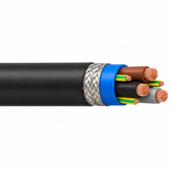
- EPR insulation, blue EPR inner sheath, tinned-copper braid and black CPE outer sheath
- Class 5 plain copper conductors
- 90 °C maximum conductor temperature
- KON and distributed-PE configurations; overall tinned-copper braid
S1BC4N8-F is a 0.6/1 kV screened submersible pump cable for variable-frequency-drive wastewater pumps, mixers and related equipment. EPR-insulated Class 5 plain copper conductors sit inside a blue EPR inner sheath. A tinned-copper braid surrounds that inner sheath, with a black CPE outer sheath protecting the assembly.
The 12 listed configurations cover KON designs and larger constructions with three distributed protective conductors. In a designation such as 3×25+3G16/3, the protective-conductor cross-section is distributed around the three phase cores. Select this arrangement together with the motor terminal drawing and the required protective-earth connection.
The overall braid provides the screen path for the drive connection; the protective conductors provide the PE circuit. Plan effective screen contact at both cable ends, with appropriate glands and bonding to the equipment enclosure. Keep the braid termination geometry and motor-cable routing consistent with the drive and motor installation instructions.
The table brings together diameter over screen, finished diameter limits, bend radii, mass and electrical data so the cable and its accessories can be selected together. Send the drive output, motor rating, route length, entry dimensions and wastewater composition when enquiring. Water depth and temperature limits are confirmed for the project after enquiry. Provide separate cable supports and mechanical pump lifting equipment.
Construction
Cable layers are listed from the conductor to the outer sheath.

| Layer | Construction |
|---|---|
| Power conductors | Plain fine-stranded copper, Class 5 to IEC 60228. |
| Insulation | EPR rubber with power core identification to DIN VDE 0293-308. |
| Protective conductor | KON or three distributed PE conductors, as identified separately in the configuration table. |
| Inner sheath | Blue EPR rubber. |
| Metallic screen | Tinned-copper braid between inner and outer sheath. |
| Outer sheath | Black water- and oil-resistant CPE compound. |
Applications
Use this construction for variable-frequency-drive wastewater pumps and submersible mixers. Match the cable to the actual equipment, route and water medium before selecting the final configuration.
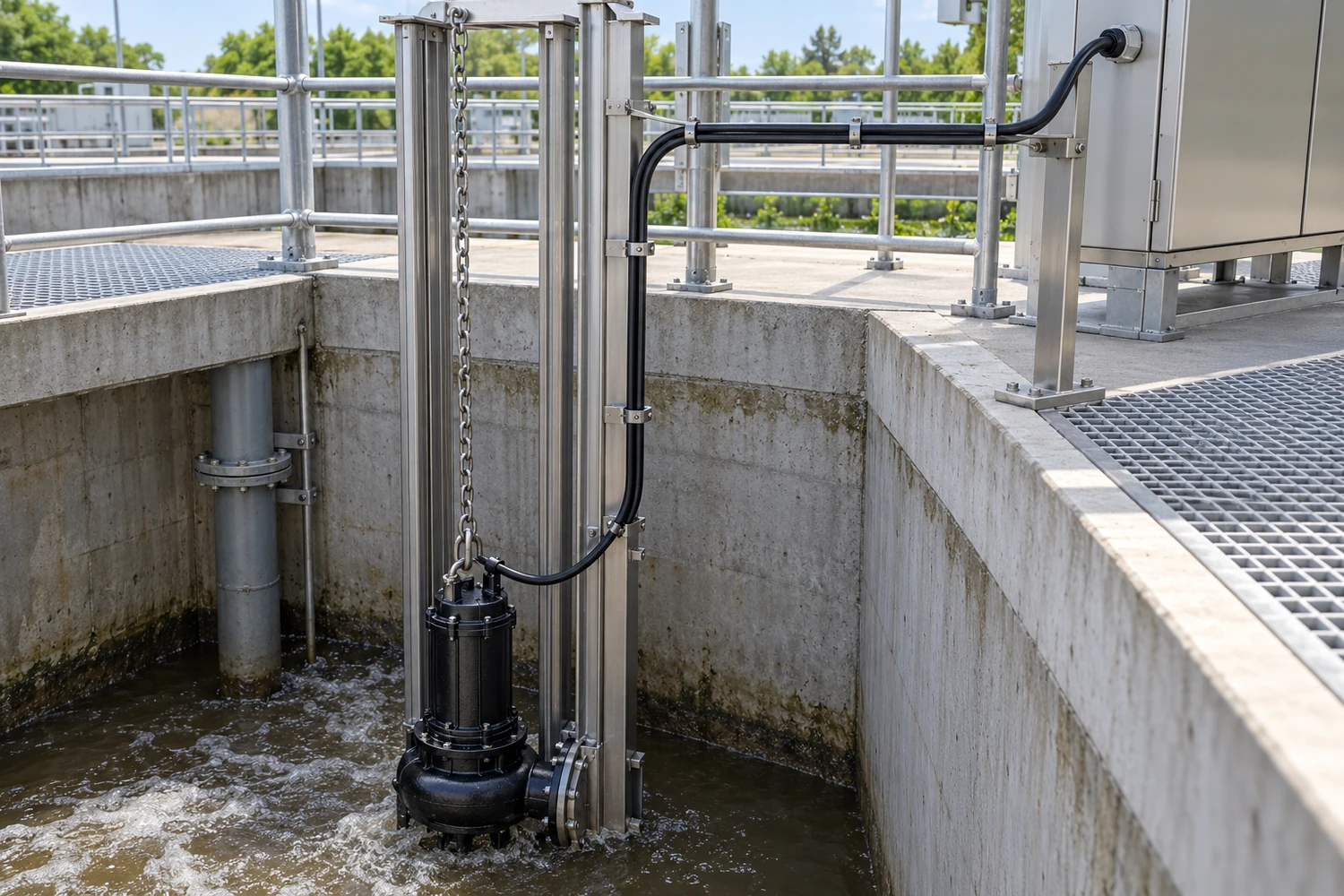
- Match the KON or distributed-PE layout to the motor and connector drawing.
- Provide effective screen contact at both cable ends; the screen and protective conductor have separate functions.
- Specify drive output, motor-cable length and entry-seal dimensions when requesting a replacement.
Keep contaminated-water routes accessible for inspection. Review aggressive chemicals and varying effluent composition individually. Provide cable support and strain relief separately from the pump lifting system.
Screen, PE and drive installation
| Selection point | Design input |
|---|---|
| Screen continuity | Use effective screen contact at both ends, coordinated with the drive and motor enclosure. |
| Protective earth | Terminate KON or distributed PE conductors according to the selected connection drawing. |
| Drive conditions | Provide output voltage, switching conditions, motor-cable length and any output filter. |
| Accessories | Match finished OD, diameter over screen and strip lengths to the gland and termination assembly. |
Related selection resources
Specifications
| Parameter | Value |
|---|---|
| Rated voltage U₀/U | 0.6/1 kV |
| Conductor | Plain flexible copper, Class 5 |
| Insulation and sheath | EPR insulation, blue EPR inner sheath, tinned-copper braid and black CPE outer sheath |
| Maximum conductor temperature | 90 °C |
| Ambient / handling conditions | −40 °C stationary; −25 °C in motion |
| Water depth and water temperature | Project operating conditions reviewed with the enquiry. |
| Short-circuit conductor temperature | 250 °C for a maximum of 5 s |
| Maximum permissible operating voltage AC | 0.7/1.2 kV |
| Maximum permissible operating voltage DC | 0.9/1.8 kV |
| Maximum permissible peak AC voltage | 2.4 kV |
| Maximum screen transfer impedance | 30 Ω/km at 30 MHz |
Current figures apply to continuous DC or 50–60 Hz AC service in air at 30 °C. The selected configuration and installation determine the applicable correction factors.
S1BC4N8-F dimensions and electrical data
| Configuration (mm²) | Conductor diameter (mm) | Diameter over screen (mm) | OD minimum (mm) | OD maximum (mm) | Minimum fixed bend radius (mm) | Minimum moving bend radius (mm) | Approximate mass (kg/km) | Maximum tensile force (N) | Current in air at 30 °C (A) | Conductor short-circuit current, 1 s (kA) |
|---|---|---|---|---|---|---|---|---|---|---|
| S1BC4N8-F 3 × 1.5/1.5KON | 1.5 | 8.7 | 9.5 | 11.1 | 33 | 56 | 174 | 67 | 23 | 0.21 |
| S1BC4N8-F 3 × 2.5/2.5KON | 2.0 | 9.7 | 10.5 | 12.1 | 48 | 73 | 230 | 112 | 30 | 0.36 |
| S1BC4N8-F 3 × 4/4KON | 2.4 | 10.7 | 11.8 | 13.4 | 54 | 80 | 310 | 180 | 41 | 0.57 |
| S1BC4N8-F 3 × 6/6KON | 2.9 | 12.2 | 13.6 | 15.2 | 61 | 91 | 389 | 270 | 53 | 0.86 |
| S1BC4N8-F 3 × 10/10KON | 3.9 | 16.6 | 17.8 | 19.8 | 79 | 119 | 693 | 450 | 74 | 1.43 |
| S1BC4N8-F 3 × 16/16KON | 5.0 | 19.4 | 20.9 | 22.9 | 92 | 137 | 1037 | 720 | 99 | 2.29 |
| S1BC4N8-F 3 × 25+3 G 16/3 | 6.3 | 24.5 | 25.3 | 28.3 | 113 | 170 | 1477 | 1125 | 131 | 3.58 |
| S1BC4N8-F 3 × 35+3 G 16/3 | 7.5 | 26.7 | 28.3 | 31.3 | 125 | 188 | 1883 | 1575 | 162 | 5.01 |
| S1BC4N8-F 3 × 50+3 G 25/3 | 8.9 | 31.0 | 33.2 | 36.2 | 145 | 217 | 2635 | 2250 | 202 | 7.15 |
| S1BC4N8-F 3 × 70+3 G 35/3 | 10.7 | 36.0 | 38.7 | 41.7 | 167 | 250 | 3633 | 3150 | 250 | 10.01 |
| S1BC4N8-F 3 × 95+3 G 50/3 | 12.3 | 41.5 | 43.7 | 47.7 | 191 | 286 | 4652 | 4275 | 301 | 13.59 |
| S1BC4N8-F 3 × 120+3 G 70/3 | 14.3 | 42.9 | 48.8 | 51.8 | 207 | 311 | 5933 | 5400 | 352 | 17.16 |
Standards
Technical references and test conditions for the specified construction.
| Item | Reference |
|---|---|
| Conductor | IEC 60228, Class 5 |
| AC voltage test | 5 kV AC for 5 minutes |
| Construction / use reference | The specified EPR/CPE construction; use guidance in DIN VDE 0298-300 / HD 516. |
| Core identification | DIN VDE 0293-308; numbered control cores where applicable. |
| Water-resistance test reference | DIN VDE 0282-16 / HD 22.16 |
| Oil-resistance test reference | DIN EN 60811-2-1 |
| Single-cable flame test reference | DIN EN 60332-1-2 |
For conductor classes and nominal metric cross-sections, see the IEC 60228 standard scope.
Related cable options
Compare these cable options by service combination, movement, load, voltage and transmission requirement.

S1BN8-F 0.6/1 kV Wastewater Pump Cable
A related cable option for a different application or duty profile.
View product
SUBCAB Cable for Submersible Pump Motors with Control Cores
A related cable option for a different application or duty profile.
View product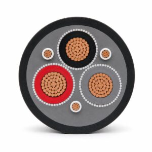
Submersible Pump Motor Cable 450/750V 0.6/1kV with Control Cores
A related cable option for a different application or duty profile.
View productRequest a cable recommendation and quotation
Send the required services, cable length, mechanical duty, environment, termination and quantity. Our team will review the application before quoting.
- Include the product name or SKU plus the required cable length and quantity.
- Attach a specification, drawing or data sheet when available.