


Drive and motor cable
VFD cable is the power cable between a variable frequency drive (VFD) and its motor, built for the drive’s fast-switching pulse voltage rather than a mains sine wave. It is also sold as VSD (variable speed drive), inverter or EMC motor cable. It usually has PE, XLPE, XLPO or EPR insulation, an overall foil-and-braid shield, and either one full-size ground conductor or three smaller ones placed symmetrically between the phases. The NEC does not define it as a cable type, so the construction decides whether a cable suits a drive output.
VFD cable vs standard power cable at a glance
Standard power cable is designed around a steady 50 or 60 Hz sine wave; a drive output is a train of steep voltage pulses, so VFD cable is built differently in three places. Choose VFD cable when the drive maker’s manual calls for a screened motor cable; choose general-purpose cable only where that manual permits it for the route.
| Choice | VFD cable | General-purpose cable | Why it matters on a drive output |
|---|---|---|---|
| Insulation | PE, XLPE, XLPO or EPR | Often PVC | NFPA 79 Annex A.12.1.1 notes that some drive-output insulation can break down from corona, with dielectric strength among the factors |
| Ground conductors | One full-size core (4G) or three symmetrical cores (3+3) | One ground conductor | The US DOE names a cable with the phases equally spaced around the ground among bearing-current measures |
| Shield | Foil plus tinned copper braid, bonded 360° at both ends | Usually none | The braid returns high-frequency current inside the cable |
Do VFDs need special cable?
A VFD needs cable built for its pulse output when the drive maker’s installation manual calls for a screened motor cable, or when output voltage, run length and conductor spacing put the insulation at risk. NEC 430.122(B) Informational Note No. 2 names those factors for drive-output conductors. Whether THHN or XHHW building wire will do on a given run is for the drive maker’s instructions to settle; a 600 V rating alone does not answer it.
A drive does not deliver a sine wave: it switches its DC bus on and off at high frequency (pulse-width modulation), and each steep voltage edge travels down the motor cable as a wave. Those edges stress insulation, drive common-mode current through the motor and couple noise into nearby circuits.
At the motor, each edge reflects because the cable’s characteristic impedance does not match the motor’s. The overshoot depends on the rise time and on the cable’s characteristics and length (Moreira et al., IEEE Transactions on Industry Applications, 2002). The US Department of Energy’s remedies are a shorter cable run, line inductors (load reactors) at the drive end of the motor cable, or a dV/dt filter (DOE Motor Systems Tip Sheet #15, 2012). Inverter-duty winding insulation is qualified on the motor under IEC 60034-18-41 and IEC 60034-18-42 and specified for inverter-duty motors in NEMA MG 1 Part 31; it is not a cable property.
Switching also creates a high-frequency common-mode voltage that couples through the motor’s parasitic capacitances and can discharge through the bearings, with the cable’s grounding path in the circuit. A shielded cable is not a cure: it lowers rotor-to-ground current but can raise circulating bearing current and leaves discharge (EDM) current unchanged (Zhu et al., IEEE Access, 2022). Insulated bearings, shaft grounding and filters are separate measures.
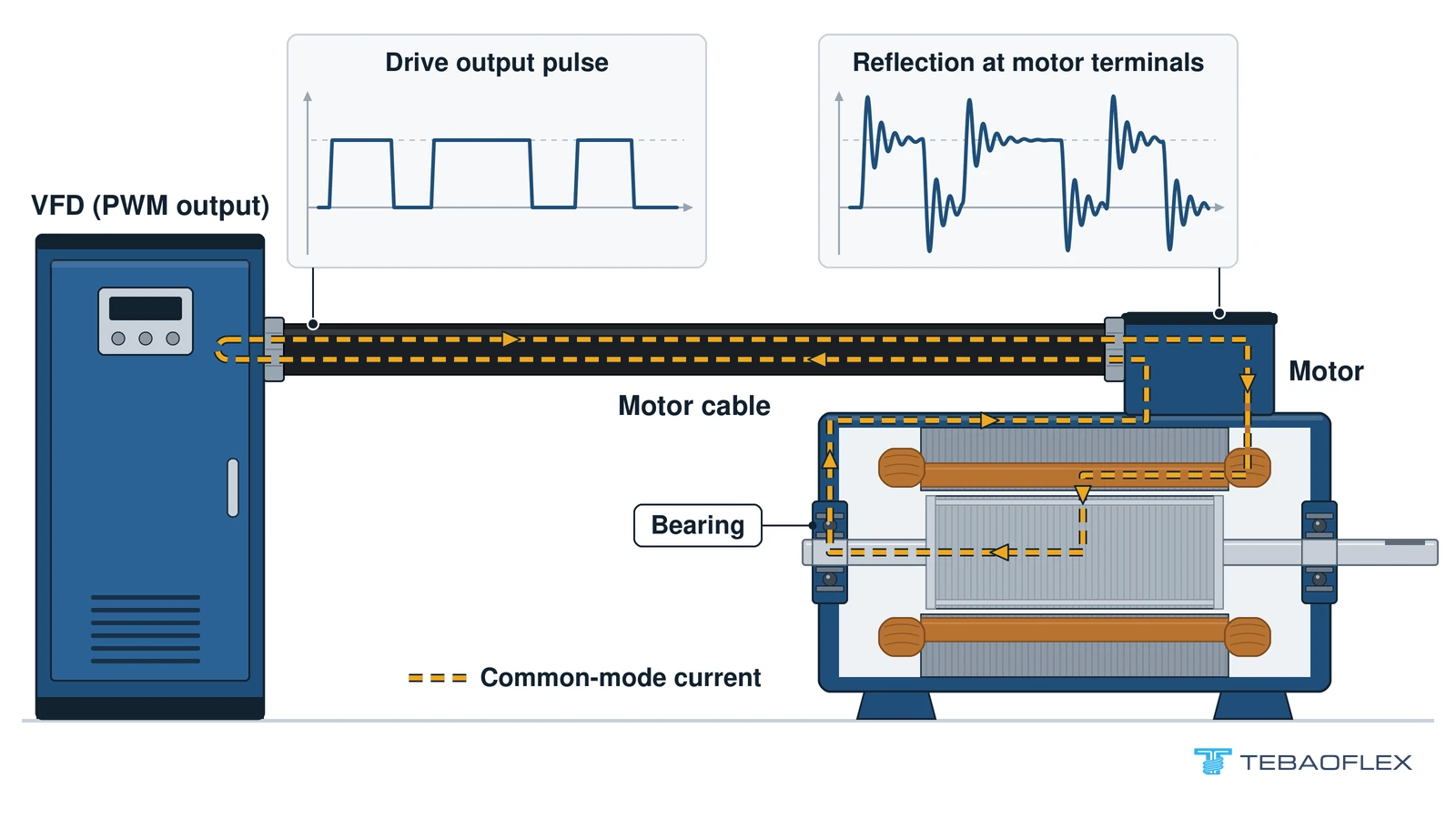
How VFD cable is built: insulation, grounds and shield
VFD cable is usually built from PE, XLPE, XLPO or EPR insulation, either one full-size earth core (4G) or three symmetrical earth cores (3+3), and a foil-plus-tinned-copper-braid screen. The insulation has to withstand repeated voltage peaks, and low capacitance matters when a long motor cable is assessed.
2YSLCYK-J and 2YSLCYK-JB use polyethylene (PE) with a 70 °C conductor limit, and 2XSLCYK-J uses XLPE with a 90 °C limit, all three on IEC 60228 class 5 copper. The 2 kV Type P construction uses XLPO, and flexible mining and festoon types use EPR, a trade-off covered in how EPR and XLPE insulation differ.
Symmetrical 3+3 grounds or one full-size ground?
A symmetrical VFD cable carries three smaller ground (protective-earth) conductors in the gaps between the three phases instead of one full-size fourth core, so every phase has the same geometry to ground. A 4G cable puts its single earth core beside two phases and opposite the third. Choose 3+3 when the drive or motor maker specifies distributed earth conductors or a symmetrical cable is part of the bearing-current measures. Choose 4G when the drive manual accepts a four-core screened cable or an existing 4G cable is replaced like for like.
The US DOE names a cable with all three phases equally spaced around the ground conductor among measures against bearing-current problems (Motor Systems Tip Sheet #15, 2012). A 3+3 layout is one way to get that symmetry, and the drive or equipment design decides the layout. Each G value in a 3+3 designation is one earth core, so 2YSLCYK-JB 3 X 50 + 3 G 10 has three 10 mm² earth cores. On parallel runs, size them to the wiring rules in force, such as the NEC in the US.
| Construction | Ground conductors | Insulation, conductor limit | Screen | Choose this when |
|---|---|---|---|---|
| 2YSLCYK-J 4 G 50 | 3 phases + 1 full-size earth | PE, 70 °C | Full-coverage foil; tinned copper braid approx. 75 % | Drive manual accepts a four-core screened cable: 2YSLCYK-J four-core motor cable with one earth core |
| 2YSLCYK-JB 3 X 50 + 3 G 10 | 3 phases + 3 symmetrical earths | PE, 70 °C | Aluminium-coated foil; tinned copper braid, nominal min. 70 %; transfer impedance max. 250 Ω/km at 30 MHz | Drive or motor maker specifies symmetrical earths: 2YSLCYK-JB symmetrical VFD cable with three earth cores |
| 2XSLCYK-J 4 G 50 or 3 X 50 + 3 G 10 | Either layout | XLPE, 90 °C | Aluminium/PETP foil and tinned copper braid | Conductor must run above PE’s 70 °C limit, up to 90 °C: XLPE-insulated 2XSLCYK-J in 4G and 3+3 versions |
All three suit fixed routes and occasional movement, not continuous drag-chain travel or repeated torsion.

Shield: foil plus tinned copper braid
The foil covers the cores and the tinned copper braid clamps all round in a gland; a galvanised steel-wire braid is armour, not a screen. Braid coverage is geometry and transfer impedance is performance, as explained in what braid coverage does and does not tell you. The 12 production lines at TEBAOFLEX’s Taicang factory include braid screening (as of September 2026).
Which codes and standards apply to VFD cable?
Neither the NEC nor NFPA 79 defines VFD cable as a type. In the US, NEC 430.122(B) and NFPA 79 4.4.2.8 apply to drive-output conductors, UL 2277 to flexible motor supply cable rated 1000 or 2000 V, and UL 1277 to Type TC tray cable where it is used. IEC 61800-3 covers the EMC of the drive system.
During the 2023 NEC revision, NEC Code-Making Panel 6 (CMP-6) wrote that “VFD cable is not defined in the NEC” (NFPA CMP-6 statement, 2021).
| Document | What it covers | Edition |
|---|---|---|
| NEC 430.122(B) Informational Note No. 2 (2023); 430.122(B)(2) Informational Note No. 2 (2026) | Drive-output conductors can break down; names voltage, frequency, current, length, spacing and dielectric strength | 2023; wording kept for 2026 |
| NFPA 79 4.4.2.8 | Drive-output conductors identified as suitable for the power characteristics | 2021 wording, unchanged in the current 2024 edition |
| UL 2277 | UL LLC Outline of Investigation covering flexible motor supply cable for VFDs, rated 1000 or 2000 V; also covers wind turbine tray cable | Edition 6, 2024 |
| UL 1277 | Type TC tray cable; “-ER” marks exposed runs; the scope does not mention drives | Edition 6, revised 2025 |
| IEC 61800-3 | EMC of the drive system, not the cable, by category C1 to C4 | Edition 4.0, 2022 |
| IEC TS 60034-25 | Guidance for converter-fed AC motors, including installation | 2022 |
The NEC note was carried unchanged into the 2026 revision (NFPA CMP-11 SR-8024, 2024). NFPA 79-2018 allowed listed flexible motor supply cable marked RHH, RHW, RHW-2, XHH, XHHW or XHHW-2, or selection to the maker’s instructions; the 2021 edition replaced both (NFPA 79 SR-20, 2020).
What type of cable is used for VFDs?
The cable used for a VFD is a screened multi-conductor power cable with PE, XLPE, XLPO or EPR insulation, sized for the motor current. North American enquiries state 600 V, 1000 V or 2000 V (UL 2277 covers the last two), AWG or kcmil and the number of grounds; IEC enquiries state 0.6/1 kV, mm² and 4G or 3+3.
| Duty | Construction | Choose this when |
|---|---|---|
| Fixed industrial motor feed, 0.6/1 kV | 2YSLCYK-J 4G, 2YSLCYK-JB 3+3 or 2XSLCYK-J (XLPE) | Choose by earth layout and conductor temperature, as in the 4G and 3+3 table |
| Fixed offshore or drilling drive feed | Type P, XLPO, overall shield, 2 kV, 1/0 AWG to 777 MCM | IEEE 1580 Type P is specified; its suitability for a drive output rests on the ground layout and shield, not the Type P name, so confirm both: 2 kV Type P cable with XLPO insulation and an overall shield |
| Mining drives that move with the machine | (N)SSHCOEU: EPR, earth split in three, tinned copper braid | Flexing duty, not unrestricted drum reeling: (N)SSHCOEU screened mining motor cable |
| Flexible or wet route needing 3+3 | (N)SSCHÖU-J: rubber, 3+3, tinned copper braid | 3+3 earths on a moving or wet route: (N)SSCHÖU-J rubber cable with a 3+3 core layout |
| Crane festoon motor supply | (N)GRDGCGOEU-J: EPR, tinned copper braid over the inner sheath, split earth from 16 mm² | Festoon loops without torsion: (N)GRDGCGOEU-J screened festoon cable |
Mining routes add their own checks for wet, moving and drive-fed circuits, set out under VFD checks in 0.6/1 kV mining cable selection.
Do VFD cables need to be shielded?
VFD cables need a shield when the drive maker’s installation instructions or the installation’s EMC requirements call for one, judged on run length, neighbouring cables and raceway. Neither NEC 430.122 nor NFPA 79 4.4.2.8 requires a shield by name. Bonded all round at both ends, a foil-and-braid screen gives the drive’s high-frequency current a low-impedance return path inside the cable.
Can VFD cable be run in conduit?
VFD cable can run in conduit where its own rating and the local wiring rules allow it; the conduit adds protection, and the screen still needs bonding at both ends. Running THHN or XHHW building wire in metal conduit instead of a screened cable is a different installation method, so confirm that the drive maker accepts it.
How to ground and terminate a shielded VFD cable
A shielded VFD cable is grounded through two separate paths: the ground conductors carry the protective earth between motor frame and drive, and the braid, bonded 360° at both ends, carries high-frequency current. Before you start, isolate and lock off the drive and let its DC bus discharge as the drive manual specifies, and have both manuals, EMC glands sized for the braid and an ohmmeter ready.
- Clamp the braid all round in the EMC gland at the drive; check full-circumference contact.
- Repeat at the motor terminal box with an EMC gland; check that the gland body is bonded to the box.
- Connect every ground conductor, all three in a 3+3 cable, to the PE terminals at both ends; check each for continuity.
- Keep the insulated earth cores as the protective-earth conductors; the braid does not replace an earth core. If the drive manual also asks for the screen ends on the PE terminal, connect them there as well and check that each connection is tight.
- Bond instrument pair screens by their own rule, one end only for analogue loops, and check that the other end stays insulated; that rule is set out for screened instrument pairs near drives.
- Ask for the measured screen continuity and resistance from the factory test, and check screen continuity again on site before energising.
A correct result has the braid clamped all round at both ends, every earth core terminated, and the braid not counted as the protective-earth conductor. The common wrong result is a braid twisted into a pigtail in place of the 360° clamp, which loses the all-round contact.
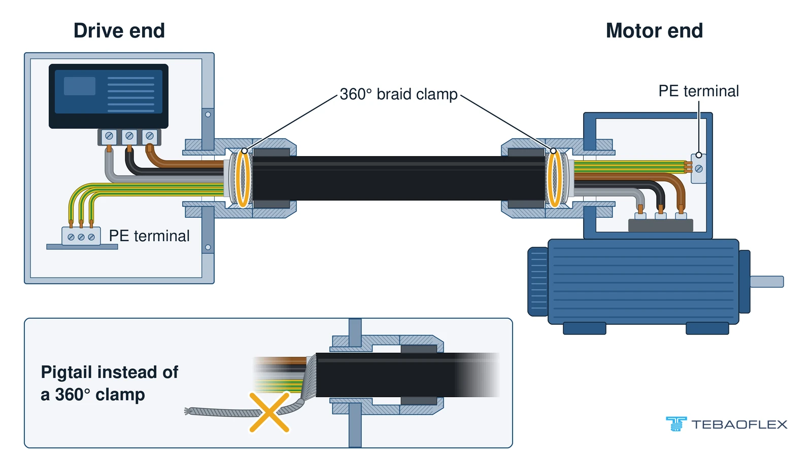
What to send with a VFD cable enquiry
A VFD cable enquiry needs the drive, motor, route and earth layout, because the drive supplier checks drive, filter and motor against the cable’s capacitance, inductance and length.
For a 6000 V pump on a medium-voltage VFD with a dV/dt filter, TEBAOFLEX gave the buyer the cable’s capacitance, 0.345 µF/km, and inductance, 0.371 mH/km, for a 180 m run. Matching drive, filter and motor was the drive supplier’s calculation, as recorded for the 6/10 kV pump cable replacement in Kazakhstan. Those two values belong to that 6/10 kV cable; for a 0.6/1 kV drive cable, ask for its own capacitance and inductance per kilometre.
- Drive model, output rating and any dV/dt or sine filter
- Motor power, full-load current and voltage
- Run length and cables in parallel
- Core layout: 4G, or 3+3 with phase and earth sizes
- Screen: coverage, transfer impedance or cross-section
- Glands and bonding points
- Duty: fixed, occasional movement, festoon, reeling or drag chain
- Ambient and exposure to water, oil or sun
- Existing cable marking, if replacing one
- Documents, such as a screen continuity test
Send the drive and route data to have the VFD cable construction confirmed; the written quotation states the construction and the lead time.
Buying questions before the first VFD cable order
Can we order a trial length of VFD cable?
A trial length of VFD cable can start at 50 m: as of August 2026, TEBAOFLEX’s minimum order is 50 m for standard and customised constructions alike, and price varies with quantity.
How long does a VFD cable order take?
A VFD cable order takes 7 to 45 working days as of August 2026, depending on product type, stock position and customisation; the written quotation confirms the lead time before you commit a shutdown window.
Which certificate covers VFD cable?
No TEBAOFLEX product certificate covers a VFD cable construction. UL-US-2449012-4 (UL 62, US) and UL-CA-2437036-5 (CSA C22.2 No. 49, Canada) cover flexible cord, and VDE 40060056 (EU market) covers EN 50525-2-21 elastomer flexible cables. TEBAOFLEX holds no UL 2277, UL 1277 TC-ER or CSA listing for VFD cables.
Questions
Is VFD cable the same as servo cable?
Not necessarily: the names overlap. The four-core family from 4G 1.5 to 10 mm² in transparent PVC is sold as 2YSLCY-JB servo cable in 4G sizes, yet it is a foil-and-braid screened 600/1000 V cable for converter-to-motor links. 2YSLCYK-JB is a 3+3 cable in black PVC, so the -JB suffix does not determine the core layout; order by the full core configuration.
Does a dV/dt filter make a shielded cable unnecessary?
A dV/dt filter does not make a shielded cable unnecessary: it slows the voltage rise to limit motor overshoot, while the screen carries high-frequency return current, and filters do not remove common-mode voltage (Zhu et al., IEEE Access, 2022).
Is a 0.6/1 kV cable the same as a 1000 V cable?
No. A 0.6/1 kV cable is rated 600 V conductor-to-earth (U0) and 1000 V between conductors (U). A North American rating such as 1000 V or 2000 V in UL 2277 is one figure, so compare the two through the drive’s output voltage.
Send the drive data, not just the word “VFD”
A label that says VFD is a promise; a cross-section is evidence. Before accepting a cable sold as VFD cable, check its datasheet or a cut sample for PE, XLPE, XLPO or EPR insulation, a 4G or 3+3 earth layout and a foil-plus-braid screen. Then send TEBAOFLEX the drive, route and earth data.