











Polymeric-Armored Type MV-105 / MP-GC Feeder Cable
Three-conductor medium-voltage power feeder cable (5 kV 133% / 8 kV 100%, 15 kV 133%, 25 kV 133% and 35 kV 133%, 2 AWG through 1000 kcmil) combining UL 1072 Type MV-105 (105 °C EPR insulation, 25%-overlap copper tape shield, 3 split bare copper grounds) and optional ICEA S-75-381 / CSA C22.2 No. 96.1 Mine Power Type MP-GC compliance with a high-strength extruded polymeric crush-resistant armor barrier and lead-free FT4 PVC jacket.
Traditional metallic interlocked armor (MC-HL / TECK90) protects medium-voltage mine and industrial feeders against mechanical impact, but adds significant weight, increases bending stiffness, corrodes in acidic mine water and requires specialized armor glands. This Three-Conductor Polymeric-Armored UL Type MV-105 / Mine Power Type MP-GC Feeder Cable replaces metallic armor with a high-strength, high-crush-resistant extruded polymeric protective barrier under a flame-retardant PVC outer sheath.
Each phase core is built to UL 1072 Type MV-105, ICEA S-93-639 / NEMA WC 74 and AEIC CS8 specifications using compact Class B annealed bare copper conductors per ASTM B3 and B496 (2 AWG through 1000 kcmil), an extruded thermoset semi-conducting strand shield (ESS), high-dielectric 105 °C Ethylene Propylene Rubber (EPR) insulation (115 mils for 5 kV 133% / 8 kV 100%, 220 mils for 15 kV 133%, 320 mils for 25 kV 133% and 420 mils for 35 kV 133%), a free-stripping semi-conducting insulation shield (EIS) and an annealed copper tape shield applied with a 25% nominal overlap.
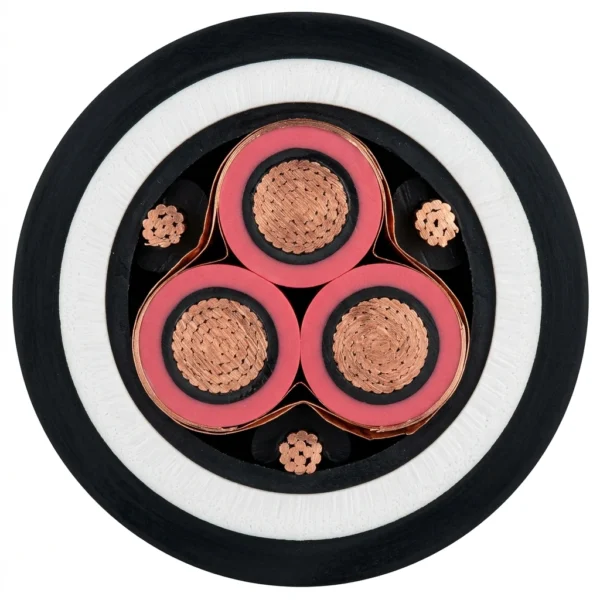
The three shielded phase cores are cabled with three symmetrical split bare copper ground conductors in the interstices and encapsulated by the co-extruded polymeric impact/crush-absorbing armor layer and a sunlight-, chemical- and flame-retardant (UL 1685 / IEEE 1202 / CSA FT4) PVC jacket. Available with optional ICEA S-75-381 and CSA C22.2 No. 96.1 Mine Power Type MP-GC dual rating for surface processing plants, underground main haulageway trays, direct burial and substation duct banks.
Explore the mining and tunneling cable range for related configurations.
Construction
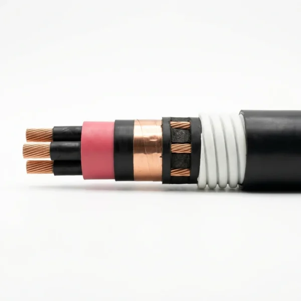
The representative cutaway illustrates the 3-conductor Polymeric-Armored UL Type MV-105 / MP-GC medium-voltage feeder cable, showing the three compact copper phase conductors, 105 °C contrasting EPR insulation between black semi-conducting ESS/EIS layers, 25%-overlap copper tape shields, three split bare copper ground conductors, the thick high-strength polymeric crush-resistant armor layer and the outer flame-retardant black PVC jacket.

| Component | Material and construction |
|---|---|
| Phase Conductors (3 × Compact Class B) | 2 AWG through 750 kcmil (5/8 kV), 2 AWG through 1000 kcmil (15 kV) or 1/0 AWG through 1000 kcmil (25 kV & 35 kV) annealed bare copper per ASTM B3 with compact Class B stranding per ASTM B496. |
| Extruded Strand Shield (ESS) | Extruded thermoset semi-conducting stress-control layer bonded over the compact copper conductor. |
| 105 °C EPR Insulation (133% Level) | Ethylene Propylene Rubber (EPR) dielectric contrasting in color with the black semi-conducting layers: 115 mils (5 kV 133% / 8 kV 100%), 220 mils (15 kV 133%), 320 mils (25 kV 133%) and 420 mils (35 kV 133%). |
| Extruded Insulation Shield (EIS) & Copper Tape | Free-stripping thermoset semi-conducting polymeric layer covered by an annealed copper tape shield applied with a nominal 25% overlap. |
| Split Grounding Conductors (3 × Bare Copper) | Three symmetrical split annealed bare copper grounding conductors (3 × 10 AWG up to 3 × 3 AWG) laid in the three core interstices. |
| Polymeric Crush-Resistant Armor Layer | High-strength, high-crush- and impact-resistant polymeric shock-absorbing armor barrier extruded concentrically over the cabled core assembly. |
| Overall Outer Jacket | Lead-free, sunlight-, chemical- and flame-retardant Polyvinyl Chloride (PVC) meeting UL 1685, IEEE 1202 and CSA FT4. |
Applications
Specify Polymeric-Armored UL Type MV-105 / MP-GC cable where medium-voltage mine and industrial feeders require mechanical crush, impact and chemical protection with smaller diameter, lighter pulling weight and tighter handling radius than metallic-armored cables.

- Mine surface concentrators, crushers, flotation plants, conveyor galleries and substation tie feeders requiring 5 kV to 35 kV (133% insulation level) distribution.
- Open uncovered cable trays, ladder racks, aerial messengers, isolated conduits in air, underground concrete duct banks and direct earth burial per NEC Articles 315 and 392.
- Dual-purpose industrial and mining facilities specifying UL 1072 Type MV-105 with optional ICEA S-75-381 / CSA C22.2 No. 96.1 Mine Power Type MP-GC compliance.
- Corrosive, wet or chemically aggressive environments where non-metallic polymeric armor eliminates galvanic armor corrosion and simplifies cable termination.
Specifications
| Parameter | Value |
|---|---|
| Standards compliance | UL 1072 Type MV-105, ICEA S-93-639 / NEMA WC 74, ICEA S-97-682 and AEIC CS8-13 (CS8-20 optional); optional ICEA S-75-381 Mine Power Type MP-GC, CSA C22.2 No. 96.1 and CSA C68.10 MV68.10. |
| Voltage classes and insulation wall | 5 kV 133% / 8 kV 100% (115 mils), 15 kV 133% (220 mils), 25 kV 133% (320 mils) and 35 kV 133% (420 mils). |
| Temperature ratings | 105 °C continuous operation (90 °C and 105 °C NEC ampacity columns provided); 140 °C emergency overload; 250 °C short-circuit rating; −40 °C cold bend and cold impact. |
| Three-installation ampacity matrix | Full NEC 2023 ampacities tabulated for (1) Isolated Conduit in Air per Table 315.60(C)(9), (2) Underground Duct per Table 315.60(C)(13) and (3) Uncovered Tray per Section 392.80(B)(1)(2) at both 90 °C and 105 °C. |
| Polymeric armor advantage | Extruded high-strength polymeric armor barrier absorbs radial crush and rock/tool impact while maintaining a smooth, corrosion-proof profile without metallic armor eddy-current losses. |
| Flame and environmental compliance | UL 1685 Vertical Flame Test, IEEE 1202 and CSA FT4; EPA 40 CFR Part 261 TCLP lead-free and OSHA acceptable. |
| Polymeric-Armored MV-105 vs EPR/CPE MP-GC | Choose Polymeric-Armored MV-105 / MP-GC (NA06) for 105 °C 133%-insulated NEC tray/duct/burial feeders with 3 split grounds and crush-resistant polymeric armor; choose EPR/CPE Type MP-GC (NA08) for MSHA lead-cured CPE borehole/mine feeders with an insulated ground-check pilot wire. |
| Conductor Size | EPR Wall (mils) | Split Ground Wires (Qty × Size) | Nom. Cond. O.D. (in) | Nom. Insulation O.D. (in) | Nom. EIS O.D. (in) | Nom. Overall Cable O.D. (in) | Nom. Cable Weight (lbs/kft) | Ampacity Conduit in Air 90°C / 105°C (A) | Ampacity Underground Duct 90°C / 105°C (A) | Ampacity Uncovered Tray 90°C / 105°C (A) |
|---|---|---|---|---|---|---|---|---|---|---|
| 2 AWG CU | 115 | 3 × 10 AWG | 0.27 | 0.56 | 0.60 | 1.85 | 2182 | 145 / 165 | 150 / 160 | 165 / 185 |
| 1/0 AWG CU | 115 | 3 × 8 AWG | 0.34 | 0.63 | 0.68 | 2.05 | 2914 | 195 / 215 | 195 / 210 | 215 / 240 |
| 2/0 AWG CU | 115 | 3 × 8 AWG | 0.38 | 0.67 | 0.71 | 2.13 | 3281 | 220 / 245 | 220 / 235 | 245 / 275 |
| 4/0 AWG CU | 115 | 3 × 7 AWG | 0.47 | 0.76 | 0.76 | 2.32 | 4344 | 290 / 320 | 285 / 305 | 325 / 360 |
| 250 kcmil CU | 115 | 3 × 6 AWG | 0.53 | 0.82 | 0.86 | 2.46 | 4974 | 315 / 350 | 310 / 335 | 360 / 400 |
| 350 kcmil CU | 115 | 3 × 6 AWG | 0.62 | 0.91 | 0.96 | 2.67 | 6247 | 385 / 430 | 375 / 400 | 435 / 490 |
| 500 kcmil CU | 115 | 3 × 5 AWG | 0.74 | 1.03 | 1.08 | 3.00 | 8349 | 470 / 525 | 450 / 485 | 535 / 600 |
| 750 kcmil CU | 115 | 3 × 4 AWG | 0.92 | 1.22 | 1.27 | 3.44 | 11635 | 570 / 635 | 545 / 585 | 670 / 745 |
| Conductor Size | EPR Wall (mils) | Split Ground Wires (Qty × Size) | Nom. Cond. O.D. (in) | Nom. Insulation O.D. (in) | Nom. EIS O.D. (in) | Nom. Overall Cable O.D. (in) | Nom. Cable Weight (lbs/kft) | Ampacity Conduit in Air 90°C / 105°C (A) | Ampacity Underground Duct 90°C / 105°C (A) | Ampacity Uncovered Tray 90°C / 105°C (A) |
|---|---|---|---|---|---|---|---|---|---|---|
| 2 AWG CU | 220 | 3 × 10 AWG | 0.27 | 0.76 | 0.80 | 2.34 | 3147 | 145 / 165 | 150 / 160 | 165 / 185 |
| 1/0 AWG CU | 220 | 3 × 8 AWG | 0.34 | 0.83 | 0.88 | 2.48 | 3830 | 195 / 215 | 195 / 210 | 215 / 240 |
| 2/0 AWG CU | 220 | 3 × 8 AWG | 0.38 | 0.86 | 0.91 | 2.56 | 4228 | 220 / 245 | 220 / 235 | 245 / 275 |
| 4/0 AWG CU | 220 | 3 × 7 AWG | 0.47 | 0.96 | 1.02 | 2.75 | 5370 | 290 / 320 | 285 / 305 | 325 / 360 |
| 250 kcmil CU | 220 | 3 × 6 AWG | 0.53 | 1.01 | 1.06 | 2.89 | 6054 | 315 / 350 | 310 / 335 | 360 / 400 |
| 350 kcmil CU | 220 | 3 × 6 AWG | 0.62 | 1.11 | 1.16 | 3.20 | 7652 | 385 / 430 | 375 / 400 | 435 / 490 |
| 500 kcmil CU | 220 | 3 × 5 AWG | 0.74 | 1.23 | 1.28 | 3.48 | 9745 | 470 / 525 | 450 / 485 | 535 / 600 |
| 750 kcmil CU | 220 | 3 × 4 AWG | 0.92 | 1.42 | 1.47 | 3.87 | 13102 | 570 / 635 | 545 / 585 | 670 / 745 |
| 1000 kcmil CU | 220 | 3 × 3 AWG | 1.07 | 1.57 | 1.62 | 4.22 | 16432 | 650 / 725 | 615 / 660 | 770 / 860 |
| Conductor Size | EPR Wall (mils) | Split Ground Wires (Qty × Size) | Nom. Cond. O.D. (in) | Nom. Insulation O.D. (in) | Nom. EIS O.D. (in) | Nom. Overall Cable O.D. (in) | Nom. Cable Weight (lbs/kft) | Ampacity Conduit in Air 90°C / 105°C (A) | Ampacity Underground Duct 90°C / 105°C (A) | Ampacity Uncovered Tray 90°C / 105°C (A) |
|---|---|---|---|---|---|---|---|---|---|---|
| 1/0 AWG CU | 320 | 3 × 8 AWG | 0.34 | 1.03 | 1.08 | 2.88 | 4855 | 195 / 215 | 195 / 210 | 215 / 240 |
| 2/0 AWG CU | 320 | 3 × 8 AWG | 0.38 | 1.06 | 1.12 | 3.01 | 5410 | 220 / 245 | 220 / 235 | 245 / 275 |
| 4/0 AWG CU | 320 | 3 × 7 AWG | 0.47 | 1.16 | 1.22 | 3.28 | 6811 | 290 / 320 | 285 / 305 | 325 / 360 |
| 250 kcmil CU | 320 | 3 × 6 AWG | 0.53 | 1.24 | 1.30 | 3.45 | 7667 | 315 / 350 | 310 / 335 | 360 / 400 |
| 350 kcmil CU | 320 | 3 × 6 AWG | 0.62 | 1.31 | 1.37 | 3.60 | 8962 | 385 / 430 | 375 / 400 | 435 / 490 |
| 500 kcmil CU | 320 | 3 × 5 AWG | 0.74 | 1.43 | 1.49 | 3.86 | 11097 | 470 / 525 | 450 / 485 | 535 / 600 |
| 750 kcmil CU | 320 | 3 × 4 AWG | 0.92 | 1.62 | 1.67 | 4.28 | 14730 | 570 / 635 | 545 / 585 | 670 / 745 |
| 1000 kcmil CU | 320 | 3 × 3 AWG | 1.07 | 1.77 | 1.83 | 4.65 | 18141 | 650 / 725 | 615 / 660 | 770 / 860 |
| Conductor Size | EPR Wall (mils) | Split Ground Wires (Qty × Size) | Nom. Cond. O.D. (in) | Nom. Insulation O.D. (in) | Nom. EIS O.D. (in) | Nom. Overall Cable O.D. (in) | Nom. Cable Weight (lbs/kft) | Ampacity Conduit in Air 90°C / 105°C (A) | Ampacity Underground Duct 90°C / 105°C (A) | Ampacity Uncovered Tray 90°C / 105°C (A) |
|---|---|---|---|---|---|---|---|---|---|---|
| 1/0 AWG CU | 420 | 3 × 8 AWG | 0.34 | 1.22 | 1.27 | 3.39 | 6291 | 195 / 215 | 195 / 210 | 215 / 240 |
| 2/0 AWG CU | 420 | 3 × 8 AWG | 0.38 | 1.24 | 1.31 | 3.50 | 7326 | 220 / 245 | 220 / 235 | 245 / 275 |
| 4/0 AWG CU | 420 | 3 × 7 AWG | 0.47 | 1.35 | 1.41 | 3.69 | 8130 | 290 / 320 | 285 / 305 | 325 / 360 |
| 250 kcmil CU | 420 | 3 × 6 AWG | 0.53 | 1.40 | 1.46 | 3.78 | 9472 | 315 / 350 | 310 / 335 | 360 / 400 |
| 350 kcmil CU | 420 | 3 × 6 AWG | 0.62 | 1.50 | 1.56 | 4.02 | 11116 | 385 / 430 | 375 / 400 | 435 / 490 |
| 500 kcmil CU | 420 | 3 × 5 AWG | 0.74 | 1.62 | 1.68 | 4.30 | 12697 | 470 / 525 | 450 / 485 | 535 / 600 |
| 750 kcmil CU | 420 | 3 × 4 AWG | 0.92 | 1.81 | 1.86 | 4.73 | 16566 | 570 / 635 | 545 / 585 | 670 / 745 |
| 1000 kcmil CU | 420 | 3 × 3 AWG | 1.07 | 1.96 | 2.05 | 5.00 | 20786 | 650 / 725 | 615 / 660 | 770 / 860 |
(1) Conduit in Air ampacities per 2023 NEC Table 315.60(C)(9) for three-conductor copper cable in isolated conduit in air at 90 °C or 105 °C conductor temperature and 40 °C (104 °F) ambient air.
(2) Underground Duct ampacities per 2023 NEC Table 315.60(C)(13) for three-conductor copper cable in underground electrical ducts (one cable per duct, Detail 1, 100% load factor, earth thermal resistivity rho = 90) at 90 °C or 105 °C conductor temperature and 20 °C (68 °F) ambient earth.
(3) Uncovered Tray ampacities per 2023 NEC Section 392.80(B)(1)(2) for three-conductor cables installed with at least one cable O.D. spacing in an uncovered cable tray at 40 °C (104 °F) ambient air (100% of Table 315.60(C)(5) values).
While the EPR dielectric is rated for 105 °C continuous operation, the maximum operating temperature of the installed circuit must not exceed the temperature rating of the medium-voltage terminations and splices.
Standards
| Standard or specification | Application |
|---|---|
| UL 1072 (Type MV-105) & ICEA S-93-639 / NEMA WC 74 | Shielded medium-voltage power cable standard from 5 kV through 35 kV at 105 °C continuous conductor rating. |
| ICEA S-75-381 & CSA C22.2 No. 96.1 (Optional) | Mine Power Feeder (Type MP-GC) and Canadian mine power cable optional compliance for mining distribution. |
| UL 1685, IEEE 1202 & CSA FT4 | Vertical cable tray flame propagation standards and −40 °C cold bend / cold impact performance. |
NEMA / ICEA S-93-639 (NEMA WC 74) shielded medium-voltage power cable standard
Related cable options
Compare these cable options by service combination, movement, load, voltage and transmission requirement.
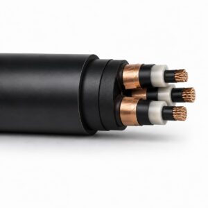
Type MP-GC 15kV Mine Power Feeder Cable
A related cable option for a different application or duty profile.
View product
Type MV-105 Flexible Single-Conductor EPR Cable, 5 kV and 15 kV
A related cable option for a different application or duty profile.
View product
Type MV-105 EPR Copper-Tape-Screened Distribution Cable, 15 kV and 35 kV
A related cable option for a different application or duty profile.
View productRequest a cable recommendation and quotation
Send the required services, cable length, mechanical duty, environment, termination and quantity. Our team will review the application before quoting.
- Include the product name or SKU plus the required cable length and quantity.
- Attach a specification, drawing or data sheet when available.