









Aircraft ground power
Voltage drop in a 400 Hz ground power cable is far higher than in the same cable at 50 or 60 Hz because its inductive reactance rises in step with frequency: about 8 times the 50 Hz value and 6.7 times the 60 Hz value. On conductors of the sizes used for aircraft, reactance is already larger than resistance. That has three practical results. A bigger conductor helps much less than it would at mains frequency, the arrangement of the conductors matters as much as their size, and the length of the cable has to be checked against the voltage required at the aircraft connector.
Why does a 400 Hz cable drop so much more voltage?
Inductive reactance is X = 2πfL, so with the same cable and the same inductance L it grows in direct proportion to the frequency f. Moving from 50 Hz to 400 Hz multiplies it by 8, and moving from 60 Hz by 6.7. ISO 6858 sets 115/200 V or 230/400 V three-phase at 400 Hz for aircraft ground power, so a large aircraft load passes through this reactance at low voltage and high current. The US Department of Defense design criteria for aircraft power, UFC 3-555-01 (quoted here from the March 2024 edition; a revision followed in July 2026), make the same point: the inductive part of the voltage drop is roughly seven times greater than on a 60 Hz system.
The table uses the 400 Hz values in that document, which come from a 1972 table for single THHN copper conductors in air. They describe that wire and not an aircraft cable, but the proportions are what matter. At 60 Hz the reactance of these sizes stays well below or close to the resistance. At 400 Hz it is larger than the resistance in every row.
| Conductor size | AC resistance at 400 Hz, Ω/km | Reactance at 60 Hz, Ω/km | Reactance at 400 Hz, Ω/km |
|---|---|---|---|
| 1/0 AWG | 0.445 | 0.107 | 0.715 |
| 2/0 AWG | 0.379 | 0.105 | 0.701 |
| 4/0 AWG | 0.278 | 0.102 | 0.681 |
| 500 kcmil | 0.180 | 0.097 | 0.648 |
| 1000 kcmil | 0.123 | 0.095 | 0.634 |
Resistance rises with frequency too, because skin and proximity effects push the current towards part of the conductor. That is a smaller change on the sizes used for ground power than the eightfold rise in reactance, but it means the DC resistance on a datasheet is the lowest the resistance can be and not its value in service.
Why doesn’t a bigger conductor solve it?
A bigger conductor lowers resistance but leaves inductance almost unchanged, and inductance is what dominates at 400 Hz. In the table above, going from 4/0 AWG to 1000 kcmil is 4.7 times the copper. Resistance falls to less than half, yet reactance falls by only about 7 %. At a power factor of 0.8 the voltage drop falls by only about 24 %, for a cable that would be far heavier and stiffer to drag across an apron.
This is why sizing a 400 Hz cable from a current table alone goes wrong. A size that carries the current without overheating can still leave the aircraft short of voltage, and the usual answer at mains frequency, going up a size, buys little. Reducing inductance means bringing the conductors that carry the current out and back closer together, or sharing each phase between more than one conductor.
How much voltage can the cable lose?
ISO 6858 defines the electrical characteristics at the aircraft attaching connector and not at the output terminals of the ground power unit, so everything the cable loses comes out of the margin. The standard requires a line drop compensation feature in the ground power facility, which raises the output voltage in proportion to the current so that the voltage at the connector stays within its limits.
UFC 3-555-01 gives a worked figure for military 400 Hz systems: with 120 V available at the source and at least 113 V required at the aircraft, the most that may be lost is 7 V per phase. Its archived predecessor explains where the 113 V comes from, a 108 V minimum inside the aircraft under MIL-STD-704 plus an allowance for the drop within the aircraft. These are US military design figures, so use them as an example of the method, and take the values for a civil project from its specification and the equipment maker.
Compensation does not remove the need to check the cable. The compensator has to be set for a known cable impedance, the same archived document warns that overcompensation can be as bad as undercompensation, and it calls for at most 118 V at no load. A compensator set for one cable may not suit a longer or different replacement.
How do you calculate voltage drop on a 400 Hz cable?
To calculate the drop, multiply the line current by the cable length and by the resistance and reactance per unit length, weighted by the power factor. This is the standard approximation for a balanced three-phase load, with the reactance worked out at 400 Hz:
Line-to-neutral drop ≈ I × length × (R cos φ + X sin φ)
Here I is the line current, R and X are per unit length and per phase, and φ is the load angle. UFC 3-555-01 uses the fuller form I × |Z|, which gives a slightly higher and more cautious figure. A 90 kVA supply at 115/200 V draws 90,000 ÷ (3 × 115), or about 261 A per phase, and we use a power factor of 0.8 lagging, the low end of the range ISO 6858 lists for its main source type.
The table compares two constructions with the same 70 mm² of copper per phase. Resistance is the IEC 60228 Class 5 maximum corrected to a conductor temperature of 70 °C, without the extra skin effect at 400 Hz. Reactance is the value measured at our factory on these two constructions, with the two conductors of each phase opposite each other in the seven-conductor cable. The drops are calculated from these figures for this one load.
| Construction | R at 70 °C, Ω/km per phase | X at 400 Hz, Ω/km per phase | 15 m | 28 m | 32 m |
|---|---|---|---|---|---|
| 4 × 70 mm² single-core bundles | 0.325 | about 0.87 | 3.1 V | 5.7 V | 6.5 V |
| 7 × 35 mm², two conductors per phase | 0.331 | about 0.36 | 1.9 V | 3.5 V | 4.0 V |
The neutral carries no current in this balanced case. An unbalanced load, connectors and any fixed feeder between the converter and the cable all add to the figures, so leave margin and ask for a calculation on your own lengths and load.
Four single-core bundles or a seven-conductor cable?
With the same copper, the seven-conductor layout has much the lower reactance, about 2.4 times lower in our measurements, and about 40 % less voltage drop at this load. Splitting each phase into two conductors placed on opposite sides of a central neutral reduces the magnetic field the phase produces, and keeps the phases close together along the whole length. US military criteria specify this layout for 400 Hz aircraft power cables: SAE AS7974 and AS5756/6 cable with six power conductors, two per phase, laid helically around a central neutral, plus six control conductors.
Low reactance is not the only requirement. Single-core bundles such as 4×(1×70+4×1) are used on pit systems and mobile units: each core has its own sheath and can be handled and terminated separately, and the 1 mm² control cores run inside the power cores. The published SAB Bröckskes catalogue gives a useful comparison of the two forms in one maker’s range: about 46.1 mm overall and 3,461 kg/km for its 4 × (70 + 4 × 1) cable, against 42 to 44 mm and about 3,320 kg/km for 7 × 35 + 6 × 4 × 1. In other words, the seven-conductor form is not heavier for the same copper. The choice depends on the duty, the connector and how the cable is stored, as our airport ground power cable guide sets out by application.
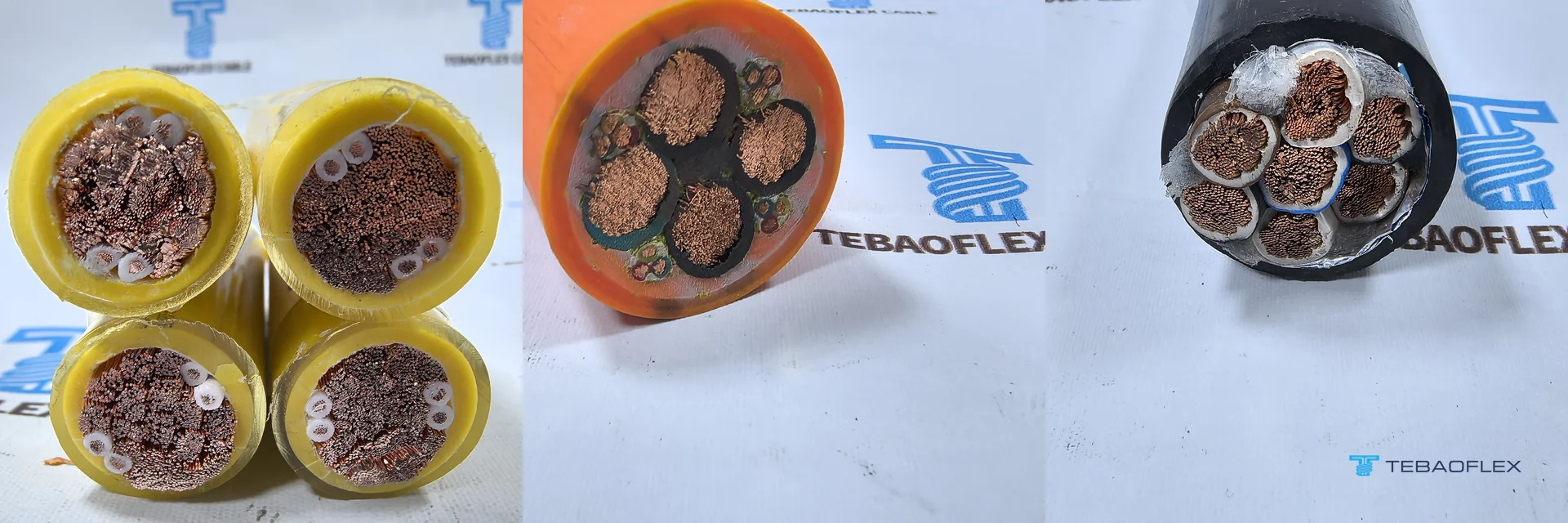
Whichever form you choose, keep the conductors close and keep steel away. Bundles should stay twisted or banded together along the length, because spreading them apart raises inductance. The archived UFC and the trade press both warn that magnetic materials near the conductors raise resistance and inductance further at 400 Hz, so do not run these cables through steel conduit or along steel structures where it can be avoided. You can compare our 7-core 400 Hz ground power cable and the 400 Hz aircraft ground power cable for the single-core form.
How long can a 400 Hz ground power cable be?
There is no single limit, because the length depends on the load, the construction and the compensation. Dividing the 7 V example by the drop per metre at 261 A gives about 34 m for the 4 × 70 mm² cable and about 56 m for the 7 × 35 mm² cable, before connectors, unbalance or any margin. In practice, the length is set from the aircraft position and the service point. UFC 3-555-01 uses 260 A assemblies of 32 m for 90 kW converters and 180 A assemblies of 27 or 32 m for 45 kW converters on Navy and Marine Corps projects, and asks for 9.1 to 30.5 m to be coordinated with the aircraft on Army projects.

The length came first on our 4×(1×70+4×1) order for an airport pit system. The buyer’s assemblies were 15 m and 28 m, and on the figures above those two lengths differ by about 2.6 V at full load. The short video below shows this four-bundle construction from the cable end through forming and sheath marking to the finished cable.
What should you send for a voltage drop check?
A useful check needs the load, every cable length, the voltage available and the duty. The constructions compared here are part of our airport ground power cable range, and these are the details to include:
- The aircraft or load: kVA or kW, power factor, and any unbalance between phases.
- The length of every assembly, plus any fixed feeder from the converter to the connection point.
- The voltage available at the source, the compensation setting, and the minimum voltage required at the aircraft connector.
- The duty: mobile unit, pit system, cable reel or fixed run, with the connector type and control core count.
With these figures the conductor layout can be checked against your real lengths and not against a catalogue value. As of August 2026, the minimum order is 50 m for standard and customised constructions alike, and lead time runs from 7 to 45 working days depending on product type, stock position and customisation. Send your cable specification for review.
Questions
Why is voltage drop higher at 400 Hz than at 50 or 60 Hz?
Voltage drop is higher at 400 Hz because inductive reactance rises in proportion to frequency: about 8 times the 50 Hz value and 6.7 times the 60 Hz value. On ground power conductor sizes, this reactance is larger than the resistance, so it sets most of the drop.
Can I use a 60 Hz cable table for a 400 Hz calculation?
Not directly. Reactance from a 60 Hz table has to be multiplied by 400/60, and a 60 Hz resistance understates the value at 400 Hz because of skin and proximity effects. Current ratings from a mains table also need checking for the same reason.
Does a larger conductor fix 400 Hz voltage drop?
Only partly. A larger conductor lowers resistance but barely changes inductance. In the UFC 3-555-01 table, 4.7 times the copper cuts the drop at a power factor of 0.8 by only about 24 %.
Does line drop compensation mean cable length no longer matters?
No. Line drop compensation raises the source voltage to offset the expected drop, but it must be set for the actual cable impedance and load. A much longer or different cable can leave the voltage at the aircraft connector too low, and overcompensation can make it too high.
What is the voltage at the aircraft connector supposed to be?
ISO 6858 sets 115/200 V or 230/400 V three-phase at 400 Hz at the aircraft attaching connector, with limits given in the standard. US military criteria use a minimum of 113 V per phase at the aircraft in their worked example. Take the value for a civil project from its specification.