










IEC 60092-353 0.6/1 kV Shipboard Power Cable
Low-voltage 0.6/1 (1.2) kV halogen-free shipboard power and multiconductor control cable built to IEC 60092-350 and IEC 60092-353. Available in unarmoured and copper-braid armoured constructions with SHF1 or oil-resistant SHF2 outer sheaths for fixed marine switchboard, deck, machinery-space and BWTS installations.
IEC 60092-353 0.6/1 (1.2) kV shipboard power cables serve fixed low-voltage distribution, motor feeders, lighting circuits and multiconductor control runs aboard commercial vessels, passenger ships and marine support craft. Unlike offshore IEC 60092-354mud-resistant RFOU/BFOU cables designed for drilling rigs, IEC 60092-353 constructions are optimized for shipboard bulkhead transits, ladder trays and enclosed deckhouse or machinery spaces.
Four core construction families cover standard and severe shipboard compartments. Unarmoured and copper-braid armoured designs are offered with either a halogen-free flame-retardant SHF1 outer sheath for accommodation, bridge and dry technical rooms, or a cross-linked oil-resistant SHF2 elastomer sheath tested to 100 °C for 24 hours for engine rooms, pump rooms and ballast water treatment systems (BWTS).
Standard power cables use IEC 60228 Class 2 stranded plain or tinned copper conductors with 90 °C XLPE insulation (250 °C short-circuit rating) in 1, 2, 3 and 4 cores from 1.5 mm² up to 120 mm², plus multiconductor control formations from 5 to 37 cores in 1.5 mm² and 2.5 mm². Flexible Class 5 tinned copper constructions are also available for compact BWTS skids and vibration-prone machinery connections.
Select the armouring, sheath compound (SHF1 or SHF2), core count and conductor cross-section using the dimensional and IEC 60092-352 current-rating tables below. Include cable route length, ambient temperature, grouping conditions and bulkhead gland sizes when requesting a technical quotation.
Explore the marine and offshore cable range for related configurations.
Construction
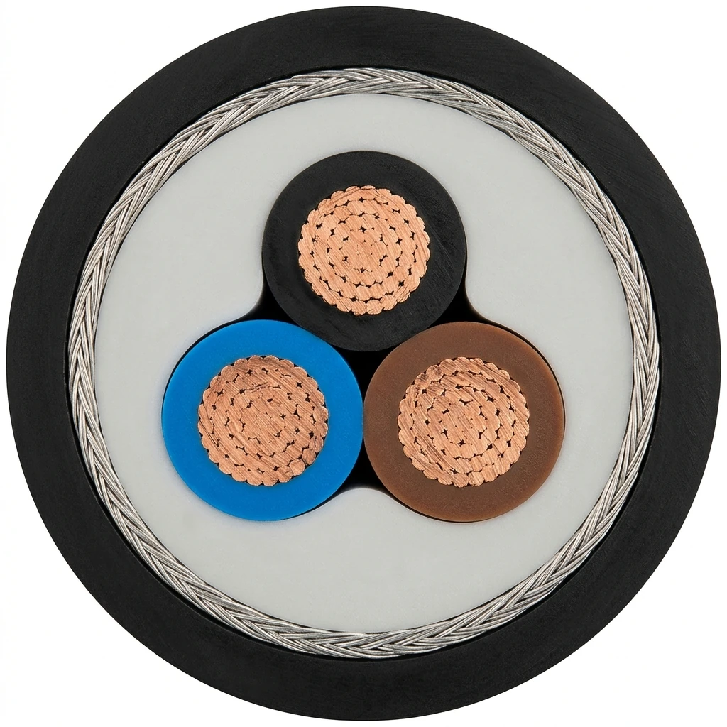
The representative cutaway illustrates a 3-core 0.6/1 kV copper-braid armoured shipboard power cable with stranded copper conductors, colour-coded XLPE insulation, non-hygroscopic inner covering, bare or tinned copper wire braid armour and a black halogen-free SHF1/SHF2 outer sheath.
| Component | Material and construction |
|---|---|
| Conductor | Stranded plain or tinned annealed copper to IEC 60228 Class 2 for fixed shipboard wiring; Class 5 flexible tinned copper available for compact machinery and BWTS skids. |
| Insulation | Cross-linked polyethylene (XLPE) to IEC 60092-351 (and IEC 60092-360 for flexible builds), rated 90 °C continuous operation and 250 °C short-circuit temperature. |
| Core identification | 2 cores: black, blue; 3 cores: black, blue, brown (or green/yellow); 4 cores: black, blue, brown, grey (or green/yellow); 5 cores and multiconductor: black numbered cores. |
| Inner covering / bedding | Extruded or lapped non-hygroscopic filler and tape assembly covering to IEC 60092-353 over the laid-up cores. |
| Metallic braid armour (armoured option) | Bare or tinned copper wire braid to IEC 60092-353 §3.8 providing mechanical protection and electromagnetic screening; omitted on unarmoured builds. |
| Outer sheath | Black halogen-free flame-retardant compound to IEC 60092-359 / IEC 60092-360: SHF1 for general shipboard spaces or cross-linked oil-resistant SHF2 (100 °C / 24 h oil test) for machinery spaces. |
Applications
Use IEC 60092-353 cables for fixed low-voltage shipboard power and auxiliary control circuits in accordance with IEC 60092-352 installation rules.

- Main and emergency switchboard feeders, distribution panels and motor power circuits up to 0.6/1 (1.2) kV AC.
- Accommodation, bridge, navigation deck and dry technical compartments using unarmoured or braided SHF1 cables.
- Engine rooms, bilge areas, fuel/lubrication separator rooms and pump rooms requiring oil-resistant SHF2 outer sheaths.
- Electromagnetically sensitive shipboard routes and exposed machinery spaces where copper wire braid armour provides EMI screening and mechanical protection.
- Ballast Water Treatment System (BWTS) power and control skids requiring flexible Class 5 tinned copper conductors and cross-linked SHF2 sheathing.
- Multiconductor auxiliary control, valve indication and alarm circuits from 5 to 37 cores in 1.5 mm² and 2.5 mm².
Specifications
| Parameter | Value |
|---|---|
| Rated voltage U₀/U (Um) | 0.6/1 (1.2) kV AC. |
| Construction standards | IEC 60092-350 and IEC 60092-353; sheath materials to IEC 60092-359 / IEC 60092-360. |
| Conductor & temperature rating | IEC 60228 Class 2 plain/tinned copper (Class 5 option); 90 °C continuous, 250 °C short-circuit. |
| Sheath options | SHF1 halogen-free standard shipboard sheath; SHF2 cross-linked oil-resistant elastomer sheath (100 °C, 24 h). |
| Bunch flame & fire performance | Flame retardant to IEC 60332-1-2; bunched fire retardant to IEC 60332-3-22 (Cat. A). |
| Halogen-free & smoke emission | Halogen-free and low corrosivity to IEC 60754-1 / IEC 60754-2; low smoke density to IEC 61034-1 / IEC 61034-2. |
| Minimum installation temperature | −15 °C minimum laying temperature; static operating temperature −15 °C to +75 °C (flexible BWTS build down to −40 °C fixed). |
| Minimum bending radius | Installed static: 4 × OD (for OD ≤ 25 mm) or 6 × OD (for OD > 25 mm); during laying: 8 × OD (≤ 25 mm) or 12 × OD (> 25 mm). |
| Construction variant | Conductor | Insulation | Armour / screen | Outer sheath | Core & size coverage |
|---|---|---|---|---|---|
| Unarmoured SHF1 (0.6/1 kV) | Class 2 plain or tinned copper (Class 5 flexible option) | XLPE to IEC 60092-351 | Unarmoured | Halogen-free SHF1 thermoplastic/elastomer to IEC 60092-359 | 1, 2, 3, 4 cores (1.5–120 mm²); 5–37 cores (1.5–2.5 mm²) |
| Copper-braid armoured SHF1 (0.6/1 kV) | Class 2 plain or tinned copper (Class 5 flexible option) | XLPE to IEC 60092-351 | Bare or tinned copper wire braid to IEC 60092-353 | Halogen-free SHF1 thermoplastic/elastomer to IEC 60092-359 | 1, 2, 3, 4 cores (1.5–120 mm²); 5–37 cores (1.5–2.5 mm²) |
| Unarmoured SHF2 oil-resistant (0.6/1 kV) | Class 2 plain or tinned copper (Class 5 flexible option) | XLPE to IEC 60092-351 | Unarmoured | Cross-linked oil-resistant SHF2 elastomer (100 °C / 24 h) to IEC 60092-359 | 1, 2, 3, 4 cores (1.5–120 mm²); 5–37 cores (1.5–2.5 mm²) |
| Copper-braid armoured SHF2 oil-resistant (0.6/1 kV) | Class 2 plain or tinned copper (Class 5 flexible option) | XLPE to IEC 60092-351 | Bare or tinned copper wire braid to IEC 60092-353 | Cross-linked oil-resistant SHF2 elastomer (100 °C / 24 h) to IEC 60092-359 | 1, 2, 3, 4 cores (1.5–120 mm²); 5–37 cores (1.5–2.5 mm²) |
| BWTS flexible shipboard power & control (0.6/1 kV) | Class 5 tinned copper to IEC 60228 | Halogen-free XLPE to IEC 60092-360 | Tinned copper wire braid + drain wire (screened option) | Cross-linked SHF2 (SHF1 option) to IEC 60092-360 | Power and control sizes for ballast water treatment systems |
| Core × cross-section | Nominal outer Ø (mm) | Approx. mass (kg/km) | Min. static bend radius (mm) | Max. DC resistance at 20 °C (Ω/km) | Continuous current at 45 °C (A) |
|---|---|---|---|---|---|
| 1 × 16 mm² | 8.5 | 190 | 50 | 1.15 | 95 |
| 1 × 25 mm² | 10.2 | 285 | 62 | 0.727 | 125 |
| 1 × 35 mm² | 11.1 | 380 | 70 | 0.524 | 155 |
| 1 × 50 mm² | 14.0 | 496 | 86 | 0.387 | 195 |
| 1 × 70 mm² | 16.0 | 713 | 76 | 0.268 | 240 |
| 1 × 95 mm² | 17.5 | 970 | 86 | 0.193 | 290 |
| 1 × 120 mm² | 20.0 | 1210 | 92 | 0.153 | 335 |
| 2 × 1.5 mm² | 9.0 | 110 | 42 | 12.1 | 20 |
| 2 × 2.5 mm² | 10.0 | 145 | 46 | 7.41 | 25 |
| 2 × 4 mm² | 11.4 | 200 | 52 | 4.61 | 34 |
| 2 × 6 mm² | 12.5 | 245 | 56 | 3.08 | 44 |
| 2 × 10 mm² | 14.0 | 365 | 62 | 1.83 | 61 |
| 2 × 16 mm² | 16.2 | 526 | 71 | 1.15 | 82 |
| 2 × 25 mm² | 19.5 | 800 | 84 | 0.727 | 108 |
| 3 × 1.5 mm² | 9.0 | 125 | 44 | 12.1 | 16 |
| 3 × 2.5 mm² | 10.0 | 170 | 49 | 7.41 | 21 |
| 3 × 4 mm² | 11.4 | 235 | 56 | 4.61 | 28 |
| 3 × 6 mm² | 12.5 | 300 | 60 | 3.08 | 36 |
| 3 × 10 mm² | 14.2 | 450 | 69 | 1.83 | 50 |
| 3 × 16 mm² | 17.0 | 690 | 82 | 1.15 | 66 |
| 3 × 25 mm² | 20.5 | 1070 | 100 | 0.727 | 88 |
| 3 × 35 mm² | 22.6 | 1400 | 168 | 0.524 | 110 |
| 3 × 50 mm² | 26.2 | 1860 | 190 | 0.387 | 135 |
| 3 × 70 mm² | 30.4 | 2590 | 218 | 0.268 | 165 |
| 3 × 95 mm² | 34.2 | 3480 | 245 | 0.193 | 203 |
| 3 × 120 mm² | 38.5 | 4350 | 272 | 0.153 | 234 |
| 4 × 1.5 mm² | 9.6 | 150 | 42 | 12.1 | 16 |
| 4 × 2.5 mm² | 10.7 | 200 | 46 | 7.41 | 21 |
| 4 × 4 mm² | 12.6 | 290 | 52 | 4.61 | 28 |
| 4 × 6 mm² | 13.6 | 370 | 56 | 3.08 | 36 |
| 4 × 10 mm² | 15.8 | 575 | 63 | 1.83 | 50 |
| 4 × 16 mm² | 19.0 | 845 | 74 | 1.15 | 66 |
| 4 × 25 mm² | 23.5 | 1350 | 88 | 0.727 | 88 |
| 4 × 35 mm² | 26.0 | 1780 | 96 | 0.524 | 110 |
| 4 × 50 mm² | 29.7 | 2360 | 169 | 0.387 | 135 |
| 4 × 70 mm² | 34.4 | 3320 | 194 | 0.268 | 165 |
| 4 × 95 mm² | 38.8 | 4460 | 217 | 0.193 | 203 |
| 4 × 120 mm² | 43.4 | 5590 | 243 | 0.153 | 234 |
| 7 × 1.5 mm² | 11.3 | 220 | 48 | 12.1 | 12 |
| 12 × 1.5 mm² | 15.5 | 370 | 68 | 12.1 | 10 |
| 19 × 1.5 mm² | 17.5 | 530 | 76 | 12.1 | 9 |
| 27 × 1.5 mm² | 22.9 | 790 | 98 | 12.1 | 8 |
| 37 × 1.5 mm² | 25.0 | 1015 | 162 | 12.1 | 7 |
| 7 × 2.5 mm² | 13.0 | 310 | 58 | 7.41 | 16 |
| 12 × 2.5 mm² | 17.0 | 513 | 74 | 7.41 | 13 |
| 19 × 2.5 mm² | 20.1 | 740 | 86 | 7.41 | 11 |
| 27 × 2.5 mm² | 24.5 | 1115 | 104 | 7.41 | 10 |
| 37 × 2.5 mm² | 28.2 | 1445 | 181 | 7.41 | 9 |
| Core × cross-section | Nominal outer Ø (mm) | Approx. mass (kg/km) | Min. static bend radius (mm) | Max. DC resistance at 20 °C (Ω/km) | Continuous current at 45 °C (A) |
|---|---|---|---|---|---|
| 1 × 16 mm² | 11.0 | 271 | 75 | 1.15 | 95 |
| 1 × 25 mm² | 13.0 | 390 | 87 | 0.727 | 125 |
| 1 × 35 mm² | 14.1 | 529 | 94 | 0.524 | 155 |
| 1 × 50 mm² | 15.9 | 661 | 104 | 0.387 | 195 |
| 1 × 70 mm² | 18.0 | 912 | 117 | 0.268 | 240 |
| 1 × 95 mm² | 19.8 | 1190 | 128 | 0.193 | 290 |
| 1 × 120 mm² | 21.9 | 1464 | 140 | 0.153 | 335 |
| 2 × 1.5 mm² | 10.2 | 252 | 70 | 12.1 | 20 |
| 2 × 2.5 mm² | 11.1 | 269 | 76 | 7.41 | 25 |
| 2 × 4 mm² | 12.8 | 374 | 86 | 4.61 | 34 |
| 2 × 6 mm² | 13.6 | 457 | 91 | 3.08 | 44 |
| 2 × 10 mm² | 15.8 | 641 | 104 | 1.83 | 61 |
| 2 × 16 mm² | 18.0 | 878 | 117 | 1.15 | 82 |
| 2 × 25 mm² | 21.6 | 1286 | 139 | 0.727 | 108 |
| 3 × 1.5 mm² | 10.8 | 252 | 84 | 12.1 | 16 |
| 3 × 2.5 mm² | 11.1 | 269 | 91 | 7.41 | 21 |
| 3 × 4 mm² | 13.2 | 374 | 102 | 4.61 | 28 |
| 3 × 6 mm² | 14.5 | 457 | 109 | 3.08 | 36 |
| 3 × 10 mm² | 16.6 | 641 | 121 | 1.83 | 50 |
| 3 × 16 mm² | 19.0 | 878 | 134 | 1.15 | 66 |
| 3 × 25 mm² | 22.8 | 1286 | 160 | 0.727 | 88 |
| 3 × 35 mm² | 25.7 | 1669 | 175 | 0.524 | 110 |
| 3 × 50 mm² | 29.0 | 2148 | 202 | 0.387 | 135 |
| 3 × 70 mm² | 33.0 | 2988 | 229 | 0.268 | 165 |
| 3 × 95 mm² | 36.7 | 4021 | 259 | 0.193 | 203 |
| 3 × 120 mm² | 42.3 | 5029 | 286 | 0.153 | 234 |
| 4 × 1.5 mm² | 12.5 | 258 | 74 | 12.1 | 16 |
| 4 × 2.5 mm² | 13.7 | 318 | 76 | 7.41 | 21 |
| 4 × 4 mm² | 15.5 | 451 | 88 | 4.61 | 28 |
| 4 × 6 mm² | 16.7 | 550 | 96 | 3.08 | 36 |
| 4 × 10 mm² | 18.7 | 787 | 109 | 1.83 | 50 |
| 4 × 16 mm² | 20.9 | 1094 | 123 | 1.15 | 66 |
| 4 × 25 mm² | 25.1 | 1612 | 146 | 0.727 | 88 |
| 4 × 35 mm² | 27.7 | 2069 | 163 | 0.524 | 110 |
| 4 × 50 mm² | 31.6 | 2691 | 183 | 0.387 | 135 |
| 4 × 70 mm² | 36.2 | 3825 | 210 | 0.268 | 165 |
| 4 × 95 mm² | 41.2 | 5089 | 232 | 0.193 | 203 |
| 4 × 120 mm² | 45.6 | 6298 | 266 | 0.153 | 234 |
| 7 × 1.5 mm² | 14.6 | 368 | 97 | 12.1 | 11 |
| 12 × 1.5 mm² | 16.3 | 580 | 107 | 12.1 | 9 |
| 19 × 1.5 mm² | 21.0 | 778 | 135 | 12.1 | 8 |
| 27 × 1.5 mm² | 22.5 | 1027 | 144 | 12.1 | 7 |
| 37 × 1.5 mm² | 31.0 | 1367 | 198 | 12.1 | 6 |
| 7 × 2.5 mm² | 15.1 | 471 | 100 | 7.41 | 15 |
| 12 × 2.5 mm² | 18.3 | 750 | 119 | 7.41 | 12 |
| 19 × 2.5 mm² | 21.3 | 1019 | 137 | 7.41 | 11 |
| 27 × 2.5 mm² | 25.6 | 1468 | 163 | 7.41 | 9 |
| 37 × 2.5 mm² | 34.0 | 1865 | 216 | 7.41 | 9 |
| Nominal cross-section | Single-core (A) | 2-core (A) | 3-core / 4-core (A) |
|---|---|---|---|
| 1.0 mm² | 18 | 15 | 13 |
| 1.5 mm² | 23 | 20 | 16 |
| 2.5 mm² | 30 | 26 | 21 |
| 4 mm² | 40 | 34 | 28 |
| 6 mm² | 52 | 44 | 36 |
| 10 mm² | 72 | 61 | 50 |
| 16 mm² | 96 | 82 | 67 |
| 25 mm² | 127 | 108 | 89 |
| 35 mm² | 157 | 133 | 110 |
| 50 mm² | 196 | 167 | 137 |
| 70 mm² | 242 | 206 | 169 |
| 95 mm² | 293 | 249 | 205 |
| 120 mm² | 339 | 288 | 237 |
| 150 mm² | 389 | 331 | 272 |
| 185 mm² | 444 | 377 | 311 |
| 240 mm² | 522 | 444 | 365 |
| 300 mm² | 601 | 511 | 421 |
| Max. conductor temp. | 35 °C | 40 °C | 45 °C | 50 °C | 55 °C | 60 °C | 65 °C | 70 °C | 75 °C | 80 °C |
|---|---|---|---|---|---|---|---|---|---|---|
| 70 °C | 1.18 | 1.10 | 1.00 | 0.89 | 0.77 | 0.63 | — | — | — | — |
| 75 °C | 1.15 | 1.08 | 1.00 | 0.91 | 0.82 | 0.71 | 0.58 | — | — | — |
| 80 °C | 1.13 | 1.07 | 1.00 | 0.93 | 0.85 | 0.76 | 0.65 | 0.53 | — | — |
| 85 °C | 1.12 | 1.06 | 1.00 | 0.94 | 0.87 | 0.79 | 0.71 | 0.61 | 0.50 | — |
| 90 °C (XLPE) | 1.10 | 1.05 | 1.00 | 0.94 | 0.88 | 0.82 | 0.74 | 0.67 | 0.58 | 0.47 |
| 95 °C | 1.10 | 1.05 | 1.00 | 0.95 | 0.89 | 0.84 | 0.77 | 0.71 | 0.63 | 0.55 |
All outer diameters and cable masses are nominal values for Class 2 copper constructions; SHF1 and SHF2 sheath options share the same nominal dimensions and masses across each core and armour series.
Maximum DC conductor resistance values at 20 °C follow IEC 60228 Class 2 plain copper. When converting measured resistance at another temperature T (between 5 °C and 100 °C) back to 20 °C, apply the IEC 60228 temperature factor Kt (e.g., Kt = 1.042 at 10 °C, 1.000 at 20 °C, 0.962 at 30 °C, 0.926 at 40 °C, 0.893 at 50 °C, 0.781 at 90 °C).
Permissible current ratings in the dimensional and reference tables apply to continuous duty at 45 °C ambient air temperature and 90 °C maximum conductor temperature in accordance with IEC 60092-352. Multiply by the ambient correction factor when machinery-space temperatures differ from 45 °C, and apply IEC 60092-352 grouping factors where multiple cables are bunched on a tray.
For single-core AC circuits above 25 mm², install cables in trefoil or flat spaced configurations with non-magnetic gland plates to control eddy-current heating in bulkheads.
Cables are manufactured and factory-tested to the referenced IEC standards; third-party marine classification witnessing or project-specific test protocols should be specified at the quotation stage.
Standards
| Standard or specification | Application |
|---|---|
| IEC 60092-350 / IEC 60092-353 | General construction, test methods and design requirements for 0.6/1 (1.2) kV shipboard power and control cables. |
| IEC 60092-351 / IEC 60092-359 / IEC 60092-360 | Cross-linked XLPE insulation (90 °C) and halogen-free shipboard sheathing compounds (SHF1 and oil-resistant SHF2). |
| IEC 60092-352 | Choice and installation of low-voltage shipboard power cables, current ratings at 45 °C ambient and correction factors. |
| IEC 60228 | Conductors of insulated cables (Class 2 stranded and Class 5 flexible plain or tinned copper). |
| IEC 60332-1-2 & IEC 60332-3-22 (Cat. A) | Single-cable vertical flame propagation test and bunched vertical flame spread test (Category A). |
| IEC 60754-1 / IEC 60754-2 & IEC 61034-1 / -2 | Halogen acid gas content, pH/conductivity of combustion gases and low smoke density verification. |
IEC 60092-353 low-voltage shipboard power cable standard scope
Related cable options
Compare these cable options by service combination, movement, load, voltage and transmission requirement.
0.6/1kV RFOU Cable for Marine & Offshore NEK 606 Projects
A related cable option for a different application or duty profile.
View product
NEK 606 BFOU Cable | P5/P12 Power & Instrumentation
A related cable option for a different application or duty profile.
View product
IEC 60092-376 150/250 V Shipboard Control Cable
A related cable option for a different application or duty profile.
View productRequest a cable recommendation and quotation
Send the required services, cable length, mechanical duty, environment, termination and quantity. Our team will review the application before quoting.
- Include the product name or SKU plus the required cable length and quantity.
- Attach a specification, drawing or data sheet when available.