

Monoconductor Wireline Logging Cable
3/16″–3/8″ (4.70–9.65 mm) · 17.35–66.7 kN breaking strength · 1,000–1,500 V DC · insulation to 315 °C · GIPS or GEIPS galvanised armour, S75 / S77 / MP35N alloy on request.
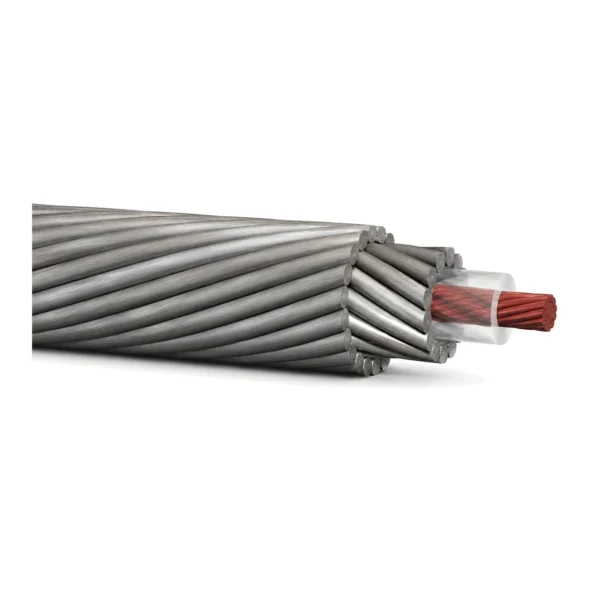
A monoconductor wireline cable is one insulated copper conductor with two contra-helical layers of steel armour wound over it. The conductor takes power down and telemetry back up. The armour carries the toolstring — and it is also the electrical return path, which is why armour condition usually shows up as a signal problem before anyone notices it as a mechanical one.
The family runs in six diameters, 3/16″ (4.699 mm) to 3/8″ (9.652 mm), with breaking strengths from 17.35 kN (3,900 lbf) to 66.7 kN (15,000 lbf) and ratings of 1,000 to 1,500 V DC. Insulation is chosen separately from diameter: polypropylene at 149 °C for shallow, cool holes; ETFE and a dual-layer FEP/ETFE at 260 °C; PFA and a 315 °C-class polymer for the hot ones.
Picking a size is not “take the strongest one the budget allows”. The cable’s own weight in water is subtracted from its working load before the toolstring gets any, so a 3/8″ is not simply better than a 1/4″: it is twice the weight per metre, it needs a 533 mm sheave instead of 356 mm, and past a certain depth the extra strength is spent carrying the extra cable. The Specifications tab has that arithmetic worked out for all six sizes rather than leaving you to do it. For the broader application context, see the oil and gas cable solution.
This is the downhole end of our oil and gas cable range; everything else in that range stays on the surface, on the platform or in the process area. Send the depth, the toolstring weight, the bottom-hole temperature and whether the well is sour. Those four numbers fix the diameter, the insulation and the armour grade — which is the entire selection.
Construction
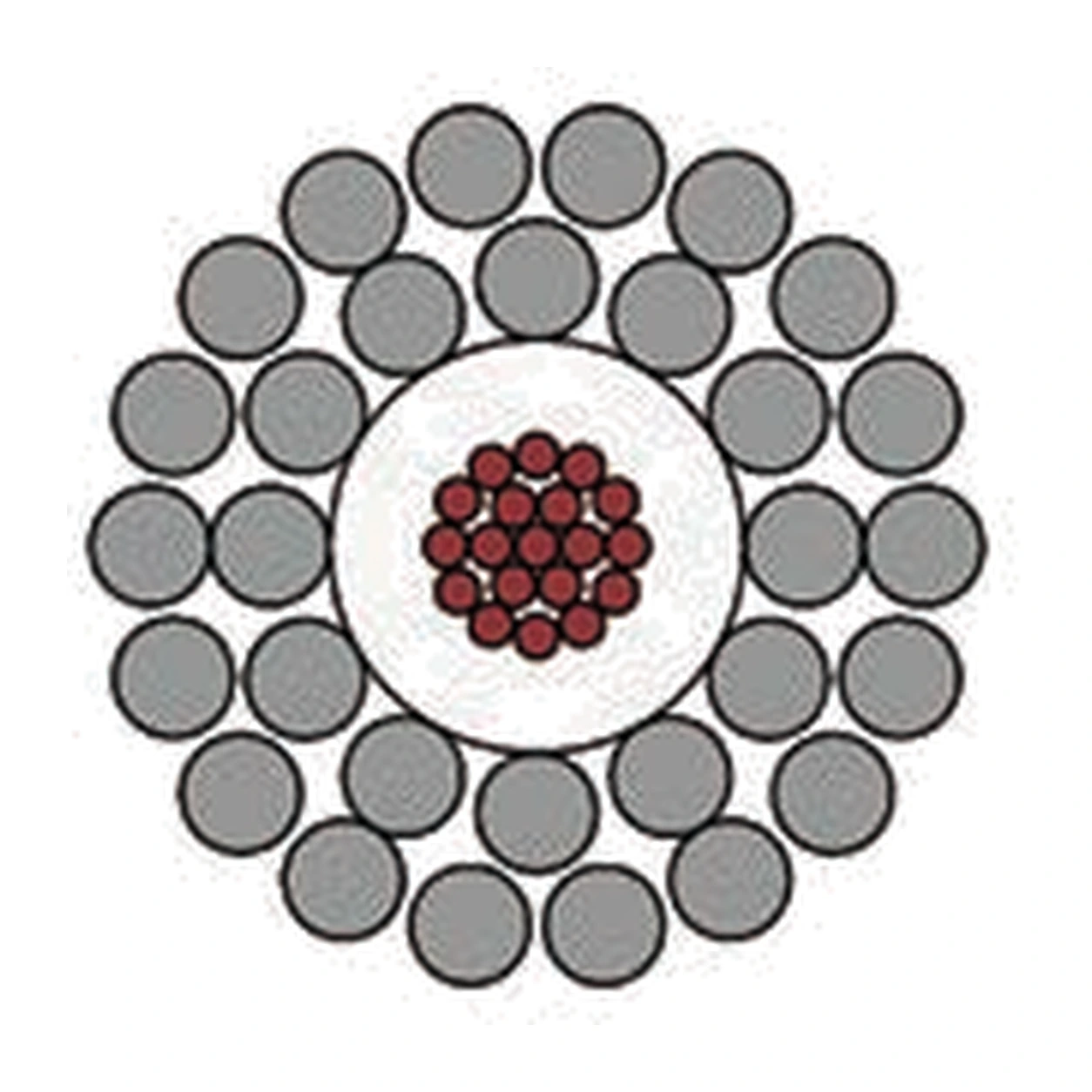
Four layers, and every one of them is doing structural work as well as electrical work. That is what separates a wireline cable from a cable that merely has armour on it.
Conductor
Stranded copper, 20 AWG through 15 AWG depending on diameter. Bare copper is standard; nickel-plated copper is specified for sour wells, where H2S will attack bare copper through any breach in the insulation.
Insulation
A single extruded wall, and the only thing between 1,500 V and a grounded steel armour that is sitting in well fluid. Material sets the temperature ceiling and the capacitance — see the Standards tab for how the two trade off.
Inner and outer armour
Two layers of high-tensile steel wire laid in opposite directions. Contra-helical laying is what keeps the cable from unwinding under load, and it is also what makes the armour a usable return conductor. The outer layer always adds exactly two wire diameters to the OD; the inner layer nests into the insulation and adds slightly less.
| Size | Conductor | Insulation OD | Inner armour | Outer armour | Cable OD |
|---|---|---|---|---|---|
| 3/16″ | 20 AWG, 7 × 0.325 mm | 2.135 mm | 12 wires @ 0.610 mm | 15 wires @ 0.757 mm | 4.699 mm |
| 7/32″ | 16 AWG, 19 × 0.302 mm | 2.743 mm | 12 wires @ 0.787 mm | 18 wires @ 0.787 mm | 5.690 mm |
| 1/4″ | 16 AWG, 19 × 0.302 mm | 3.124 mm | 12 wires @ 0.909 mm | 18 wires @ 0.909 mm | 6.553 mm |
| 9/32″ | 15 AWG, 19 × 0.361 mm | 3.480 mm | 12 wires @ 1.016 mm | 18 wires @ 1.016 mm | 7.315 mm |
| 5/16″ | 15 AWG, 19 × 0.361 mm | 3.937 mm | 12 wires @ 1.130 mm | 18 wires @ 1.130 mm | 8.179 mm |
| 3/8″ | 15 AWG, 19 × 0.361 mm | 4.648 mm | 12 wires @ 1.334 mm | 18 wires @ 1.334 mm | 9.652 mm |
Armour grade is GIPS (galvanised improved plough steel) or GEIPS (extra improved) as standard. For corrosive wells the same geometry is built in S75, S77 or MP35N alloy — that changes the strength and, more importantly, the electrical behaviour. It has its own page.
Applications
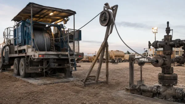
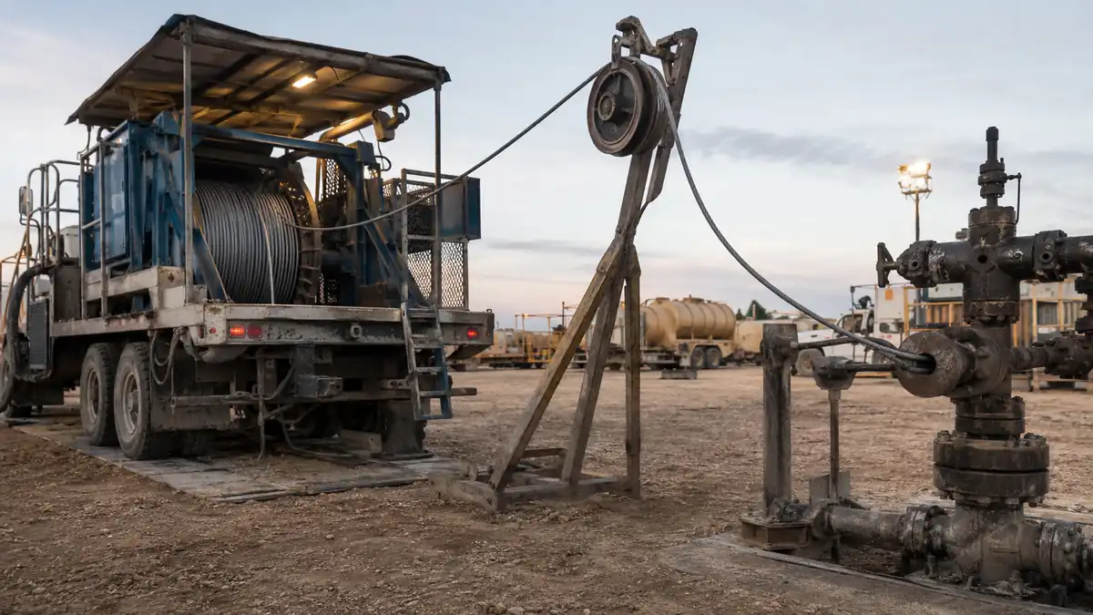
This is a cased-hole and open-hole logging cable. It runs powered tools on the end of a winch line: anything that needs current down and data back, at depth, through well fluid.
Where it is used
| Operation | What the cable is doing | Typical size |
|---|---|---|
| Open-hole logging | Powering resistivity, sonic, density and neutron tools; carrying the full toolstring | 9/32″ – 3/8″ |
| Cased-hole logging | CBL/VDL, production logging, corrosion inspection | 1/4″ – 5/16″ |
| Perforating and setting | Firing perforating guns, setting plugs and packers | 1/4″ – 5/16″ |
| Thru-tubing and slim hole | Memory and light powered tools where the restriction rules out a big cable | 3/16″ – 7/32″ |
| Deep and deviated wells | Long runs where cable self-weight, not tool weight, sets the limit | 3/8″ |
| Coring and sidewall sampling | High overpull events, repeated jarring | 5/16″ – 3/8″ |
Where it is the wrong cable
It is not a slickline — there is no conductor in slickline and no way to power a tool. It is not an oil and gas surface cable: nothing about a Type P or NEK 606 build survives being wound onto a winch drum under 40 kN. And if the well is sour, or the bottom-hole temperature is past 260 °C, or the operation runs without grease injection, the sibling pages linked below are the right starting point instead.
Specifications
All figures are for the standard galvanised-steel (GIPS/GEIPS) build. Alloy armour changes strength and armour resistance — those numbers are on the sour-service page.
Mechanical and electrical, by size
| Size | OD | Breaking strength | Working load | Min. sheave Ø | Voltage | Conductor Rdc | Armour Rdc |
|---|---|---|---|---|---|---|---|
| 3/16″ | 4.699 mm | 17.35 kN (3,900 lbf) | 8.67 kN (1,950 lbf) | 305 mm | 1,000 V DC | 32.2 Ω/km | 21.0 Ω/km |
| 7/32″ | 5.690 mm | 24.9 kN (5,600 lbf) | 14.9 kN (3,360 lbf) | 356 mm | 1,200 V DC | 13.1 Ω/km | 14.4 Ω/km |
| 1/4″ | 6.553 mm | 31.1 kN (7,000 lbf) | 18.7 kN (4,200 lbf) | 356 mm | 1,200 V DC | 13.1 Ω/km | 9.84 Ω/km |
| 9/32″ | 7.315 mm | 44.5 kN (10,000 lbf) | 26.7 kN (6,000 lbf) | 406 mm | 1,500 V DC | 9.2 Ω/km | 9.2 Ω/km |
| 5/16″ | 8.179 mm | 50.3 kN (11,300 lbf) | 30.2 kN (6,780 lbf) | 457 mm | 1,500 V DC | 9.2 Ω/km | 6.9 Ω/km |
| 3/8″ | 9.652 mm | 66.7 kN (15,000 lbf) | 40.0 kN (9,000 lbf) | 533 mm | 1,500 V DC | 9.2 Ω/km | 4.92 Ω/km |
Minimum insulation resistance is 457 MΩ·km across the range. OD tolerance is +0.13 / −0.05 mm on all sizes.
How deep before the cable is carrying itself?
Working load minus the weight of the cable already in the hole is what the toolstring actually gets. Below, weight in water for the heaviest insulation build, subtracted from the maximum working load. Read across to the depth you run and the number is your remaining payload, before overpull allowance.
| Size | Weight in water | Payload left at 3,000 m | at 5,000 m | at 7,000 m |
|---|---|---|---|---|
| 3/16″ | 83 kg/km | 636 kg | 470 kg | 304 kg |
| 7/32″ | 122 kg/km | 1,158 kg | 914 kg | 670 kg |
| 1/4″ | 155 kg/km | 1,440 kg | 1,130 kg | 820 kg |
| 9/32″ | 201 kg/km | 2,119 kg | 1,717 kg | 1,315 kg |
| 5/16″ | 247 kg/km | 2,334 kg | 1,840 kg | 1,346 kg |
| 3/8″ | 338 kg/km | 3,068 kg | 2,392 kg | 1,716 kg |
Read the 3/16″ row across and you can watch a cable eat itself: at 7,000 m it has spent 66 % of its working load carrying its own weight, and 304 kg is all that is left for tools. The 9/32″ spends 52 % over the same depth. The small cable is not just weaker — it gets proportionally weaker the deeper you go, which is the arithmetic a table of breaking strengths hides.
Stretch, and what it does to your depth
Elongation = stretch coefficient × depth in km × tension in kN ÷ 5. Worked out for a 5,000 m run:
| Size | Stretch coefficient | Elongation at 5 kN | at 10 kN |
|---|---|---|---|
| 3/16″ | 4.5 m/km/5kN | 22.5 m | — (above working load) |
| 7/32″ | 2.8 m/km/5kN | 14.0 m | 28.0 m |
| 1/4″ | 2.14 m/km/5kN | 10.7 m | 21.4 m |
| 9/32″ | 1.8 m/km/5kN | 9.0 m | 18.0 m |
| 5/16″ | 1.35 m/km/5kN | 6.8 m | 13.5 m |
| 3/8″ | 1.125 m/km/5kN | 5.6 m | 11.3 m |
Twenty-two metres of stretch on a 3/16″ run is not a rounding error — it is the difference between perforating the right interval and the one above it. Depth correction is not optional on the small sizes.
Insulation options
| Insulation | Max continuous | Character | Best for |
|---|---|---|---|
| Polypropylene | 149 °C (300 °F) | Cheapest, lowest capacitance of the low-temp options | Shallow, cool holes |
| ETFE | 260 °C (500 °F) | Hardest wall; poorer dielectric | Where crush and ridging are the problem |
| FEP/ETFE dual layer | 260 °C (500 °F) | FEP dielectric under an ETFE armour-facing skin | Horizontal and extended-reach wells |
| PFA | 260–288 °C (500–550 °F) | Best dielectric of the fluoropolymers | Vertical hot wells — see the note on the high-temperature page |
| 315 °C-class polymer | 315 °C (600 °F) | Top of the range | Geothermal, steam, deep HPHT |
Standards, designation and cable care
How wireline cables are designated
There is no single ISO or IEC number for wireline cable the way there is for a UL AWM style. The industry runs on descriptive part codes, and there are two families you will see in an RFQ.
The first spells out the build in order: conductor count — insulation code — nominal OD in thousandths of an inch — inner/outer armour wire counts — armour material — conductor strand count. So a single-conductor, FEP/ETFE, 0.258″, 12-over-18 galvanised, 19-strand cable reads as a six-field string in exactly that order. The second family is shorter: a conductor count, the letter N, and the OD in hundredths of an inch, with insulation and armour appended.
Send us either one and we will read it. Send us the well instead and we will write it for you — that is usually faster and it catches the mismatches a part number hides.
Standards that actually apply
| Standard | What it governs here |
|---|---|
| NACE MR0175 / ISO 15156 | Defines sour service and qualifies materials for H2S. Sets the 0.05 psia partial-pressure threshold that decides whether galvanised armour is acceptable at all. |
| ASTM A1007 / plough-steel wire grades | The GIPS / GEIPS / GEEIPS tensile classes the armour wire is drawn to. |
| API RP 9B (analogous practice) | Sheave-to-line-diameter ratios and inspection practice, borrowed from wire rope. |
| IEC 60228 | Copper conductor resistance classes for the centre conductor. |
Torque, birdcaging and the 20-to-30-run rule
Contra-helical armour always leaves residual torque, and it rises with tension. A cable under 40 kN wants to rotate far more than the same cable under 8 kN. If that rotation is not allowed and then released in a controlled way, the outer armour loosens in patches, the cable birdcages, and the conductor gets compressed until it shorts to armour. Normalising the cable every 20 to 30 runs pulls the loose areas back in. Cable that curls while lying on the ground is telling you it is overdue.
Frequently asked
What is the difference between wireline and slickline?
Slickline is a single solid wire with no conductor — mechanical work only. Wireline cable has an insulated conductor inside the armour, so it can power tools and carry telemetry. Everything on this page is wireline.
Why is the armour part of the electrical circuit?
A monoconductor cable has exactly one insulated conductor, so the return path has to be the armour and the wellbore. That is why armour DC resistance is on the spec table, and why corroded or loose armour shows up as a signal problem first.
Can I use a smaller sheave than the minimum?
You can, and the cable will pay for it. Below the minimum sheave diameter the outer armour wires yield on every pass instead of flexing, and fatigue life drops sharply. The 305 to 533 mm figures on the spec table are minimums, not targets — bigger is always better.
What lengths are supplied?
Continuous lengths are built to the run, on the drum size you specify. Tell us the reel dimensions and the flange capacity along with the length.
Bare or nickel-plated conductor?
Bare copper for sweet wells. Nickel-plated copper wherever H2S is present, because a single insulation breach in a sour well will attack bare copper along the length of the cable rather than at one point.
Related cable options
Compare these cable options by service combination, movement, load, voltage and transmission requirement.
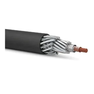
Greaseless Jacketed Wireline Cable
A related cable option for a different application or duty profile.
View product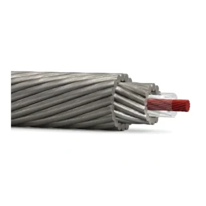
Sour Service Wireline Cable
A related cable option for a different application or duty profile.
View product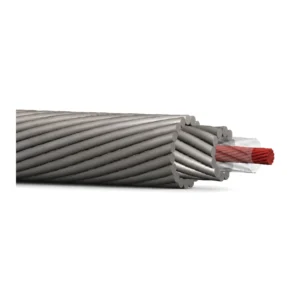
High Temperature Wireline Cable
A related cable option for a different application or duty profile.
View productRequest a cable recommendation and quotation
Send the required services, cable length, mechanical duty, environment, termination and quantity. Our team will review the application before quoting.
- Include the product name or SKU plus the required cable length and quantity.
- Attach a specification, drawing or data sheet when available.