

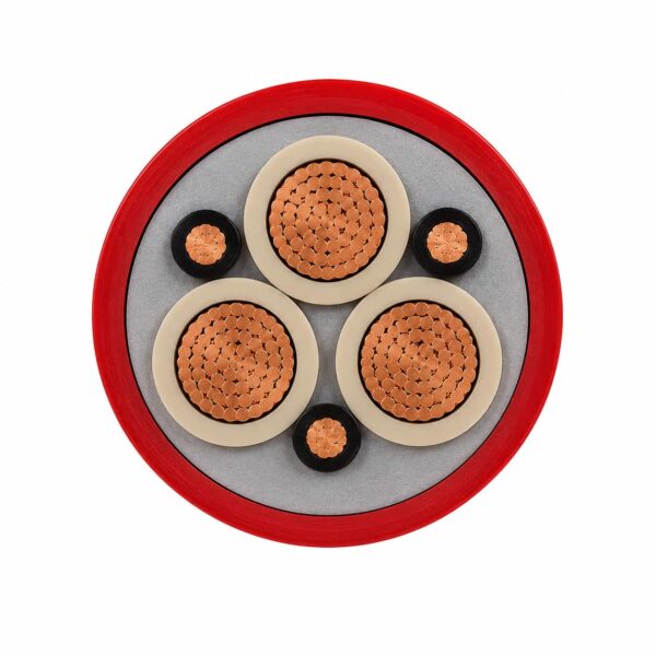
NTSCGEWOU / (N)TSCGEWÖU+FO Medium Voltage Crane Reeling Cable
NTSCGEWOU / (N)TSCGEWÖU medium-voltage crane reeling cable, also written NTSCGEWÖU or NTSCGEWOEU, supplies moving port and mining equipment through motorized cable reels. The screened EPR core system and reinforced rubber sheath are intended for repeated bending, direction changes and torsional reel duty.
- Voltage classes: 3.6/6 kV, 6/10 kV, 8.7/15 kV and 12/20 kV
- Conductor: flexible Class 5 copper
- Insulation: screened EPR medium-voltage system
- Reinforcement: high-tensile anti-twisting braid between sheath layers
- Travel speed: up to 180 m/min
- Temperature: -30°C to +80°C flexing; -50°C to +80°C fixed
- Fibre-optic version NTSCGEWOU+FO / (N)TSCGEWÖU+FO: 12, 18 or 24 optical fibres, single-mode 9/125 µm or multimode 62.5/125 µm, built at 3.6/6 kV, 6/10 kV and 8.7/15 kV
Send the voltage, conductor size, earth-core arrangement, reel geometry, travel speed, bend path and installed length for technical review.
NTSCGEWOU Cable for Medium-Voltage Crane Reels
NTSCGEWOU, written (N)TSCGEWÖU in the VDE designation and also spelled NTSCGEWÖU or NTSCGEWOEU, is a screened medium-voltage reeling cable for motorized drums on container cranes, ship unloaders, stackers, reclaimers and heavy mobile mining equipment. It combines flexible copper conductors, an EPR insulation system and a reinforced rubber sheath for routes that repeatedly wind, unwind and change direction.
This page is for dynamic crane-reel duty. Do not select it from voltage and conductor size alone: reel diameter, deflection pulleys, S-bends, acceleration, suspended length and torsion all affect cable life. The stated family covers 3.6/6 kV through 12/20 kV and travel speeds up to 180 m/min, while HVR-D / FO configurations can add 12 or 24 optical fibres when power and communications must share the moving route.
- Suitable for: high-duty motorized reel systems on port and bulk-material equipment.
- Confirm before ordering: voltage class, conductor size, earth arrangement, drum and roller dimensions, speed and bend path.
- Choose another construction when: the route is flat, trailing rather than reeling, or requires a different fibre or monitoring architecture.
NTSCGEWOU+FO / (N)TSCGEWÖU+FO: Reeling Cable with Integrated Fibre Optics
NTSCGEWOU+FO, written (N)TSCGEWÖU+FO in VDE form, is this reeling cable with an optical-fibre element added to the core assembly, so crane power and data share one reel. The suffix +FO (German: LWL, Lichtwellenleiter) marks the fibre element; the rest of the designation still describes the medium-voltage power cable. TEBAOFLEX has built NTSCGEWOU+FO at 3.6/6 kV, 6/10 kV and 8.7/15 kV with 12, 18 or 24 fibres, in single-mode 9/125 µm or multimode 62.5/125 µm.
A typical NTSCGEWOU+FO 6/10 kV build is 3×70+2×35/2+12FO (62.5/125): three 70 mm² phase conductors, a 35 mm² protective earth split into two conductors, and 12 multimode fibres. Other (N)TSCGEWÖU+FO 6/10 kV builds use 50 mm² phase conductors, and the 8.7/15 kV builds add a 20×2.5 mm² control element and 24 single-mode fibres. The built constructions are listed in the Specifications tab; diameter, weight and fibre test values come from the order datasheet.
What does +FO mean in NTSCGEWOU+FO?
+FO means the cable carries an integrated fibre-optic element in addition to its medium-voltage power, earth and any control cores. The construction string gives the fibre count and type: 12FO (62.5/125) is 12 multimode fibres, and 24FO (9/125) is 24 single-mode fibres.
Is NTSCGEWOU the same cable as (N)TSCGEWÖU?
Yes. NTSCGEWOU and NTSCGEWOEU are keyboard spellings of (N)TSCGEWÖU, used when the umlaut Ö is not available. (N)TSCGEWÖU is the German VDE-style designation of this medium-voltage reeling cable, and this page covers both the power-only and the +FO versions.
Explore the port and festoon cable range or review container-crane cable selection before submitting the project data.
NTSCGEWOEU Cable Construction
The layer system separates medium-voltage electrical-field control from the mechanical reinforcement required for continuous reel movement. The illustration is explanatory; the approved order drawing controls the final layer dimensions and core arrangement.
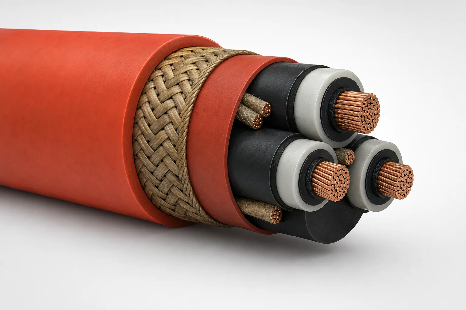
| Layer | Confirmed construction detail | Buyer relevance |
|---|---|---|
| Conductor | Highly flexible, finely stranded copper; Class 5 reference to IEC 60228. | Supports repeated bending in a moving reel route. |
| Conductor screen | Semiconductive layer around each power conductor. | Forms the inner part of the medium-voltage field-control system. |
| Insulation | EPR-MV insulation in a screened sandwich construction. | Provides the verified insulation system for the stated voltage classes. |
| Insulation screen | Semiconductive outer layer around each power core. | Completes the screened core construction. |
| Inner sheath and reinforcement | Inner sheath with a high-tensile synthetic-yarn anti-torsion braid. | Helps stabilize the cable under reel tension and changes of direction. |
| Outer sheath | High-wear synthetic rubber compound. | Protects the moving cable through rollers and drum cycles. |
| FO option | 12 or 24 fibres in loose tubes for the HVR-D / (N)TSCGEWOEU-FO configuration. | Allows a project-specific moving power-and-data route. |
Construction Boundary
Do not treat a neighbouring trailing, water-service or flat reeling designation as a drop-in substitute. Match the exact cable marking and confirm the conductor, earth-core, screen, braid and optional fibre arrangement against the equipment drawing.
Reeling route geometry to DIN VDE 0168
Four separate numbers govern a reeling route, and only one of them is a bending radius. The drum core diameter is the figure most often missed, because a drum can satisfy the bending radius and still be too small at its core.
| Route element | Limit | What it constrains |
|---|---|---|
| Drum core diameter | At least 25 × the cable diameter | The bare drum barrel, before any cable is wound on. A separate check from the bending radius. |
| Bending radius on guide and deflection pulleys | At least 15 × the cable diameter | Every diversion roller in the route, not just the first. |
| Distance between two curves | At least 20 × the cable diameter | S-shaped deflections and any change to another plane. |
| Spacing between individual pulleys | Narrow enough that the cable cannot become misshaped under maximum permissible tensile stress | Set by the route, not by a single figure; state the layout with the enquiry. |
Maximum long-term tensile load
Referred to the overall cross-section of the phase conductors, the reference builds carry different long-term limits, and the dynamic peak is common to both.
| Build | Maximum long-term tensile load |
|---|---|
| TS reference build | 15 N/mm² |
| TTS reference build | 20 N/mm² |
| Dynamic peak, either build | Should not exceed 25 N/mm² |
Reference bending radii by voltage class
The reference catalogue splits the bending radii at 1 kV. Cables designed specifically for trailing allow smaller radii in free movement, but those values depend on the build and are quoted separately.
| Route | Up to 1 kV | Above 1 kV |
|---|---|---|
| Fixed installation | 4 × D | 6 × D |
| On drums | 6 × D | 12 × D |
| On deflection pulleys | 7.5 × D | 15 × D |
| Moving freely | 5 × D | 10 × D |
What the variant suffixes mean
Enquiries for this family arrive under a range of reference designations. The suffix is not cosmetic: it states which mechanical problem the build solves, and that is what has to match the guidance system.
| Reference build | What it adds | Route it suits |
|---|---|---|
| T | The standard reeling construction: class 5 tinned copper, 3GI3 EPR insulation with an inner semi-conducting layer from 3 kV and an outer field-limiting layer from 6 kV, GM1b inner sheath, red 5GM3 outer sheath | Motorised reeling where deflection stays in one plane. |
| TT | Twist protection | Guiding systems with deflections in several planes, or with the reel axis in the direction of travel. |
| TZ | Strain relief and improved flexibility | Applications with increased mechanical tension. |
| TS and TTS | New-generation builds; the tensile limits above apply | Motorised reeling on monospiral or level-wind reelers. |
| N | Continuous protection between the inner and outer sheath against accidental touching, with the earth conductor split and placed over the outer semi-conductive layers | Emergency power supply, and floating dredges. |
| Special builds | Braided armour, or a waterproof inner sheath | Braided armour for pull and pressure loads in trailing operation; waterproof inner sheath for permanent operation in water. |
Earth conductor arrangements
The earth conductor can be incorporated as a fourth core, or distributed within the outer interstices. In special cases, such as floating dredges or emergency cables, it is split up and placed over the outer semi-conductive layers. The arrangement changes the termination design, so it is stated with the order rather than inferred from the cross-section.
Integrated optical fibre builds
Both reference FO builds twist the cores so that two split earth cores sit in two of the three interstices and the protected optical element occupies the third. The outer 5GM3 sheath is reinforced with an inserted braid of glass fibres, which serves as the torsion protection. The difference between them is the fibre count.
| Reference build | Optical element | Sheath marking |
|---|---|---|
| TT LWL | Normally 2 to 12 graded-index fibres of 50/125 µm; other type or number on request | Red |
| TTS LWL | Normally 36 fibres, in 50/125 µm, 62.5/125 µm and 9/125 µm sizes. Note that 50/125 and 62.5/125 are multimode geometries while 9/125 is single-mode, so the fibre type has to be stated and not inferred from the count | Red with a yellow stripe |
Integrated fibre removes the need for separate control and data cables on the same route, and electrical and optical terminations can be fitted in the workshop when the type and core lengths are specified with the order. The fibre count and termination interface supplied against this page are those stated in the Specifications section; the counts above are the reference-catalogue figures and are given for matching a designation.
For 3.6/6 kV open-pit machine reeling selected by drum axis and deflection direction, compare 6-CHCU trailing and reeling cable. For semi-fixed medium-voltage mine distribution rather than continuous reeling, see (N)TSCGEWÖU mine distribution cable.
Reference note: for enquiries marked TENAX-T, TENAX-TT, TENAX-TZ, TENAX-TS, TENAX-TTS, TENAX-TT LWL or TENAX-TTS LWL, TEBAOFLEX manufactures to the (N)TSCGEWOEU designation and the construction shown, and is not affiliated with the trademark holder.
Applications for NTSCGEWOEU Reeling Cable
This cable family is intended for mobile equipment where a motorized reel repeatedly pays out and recovers medium-voltage power under bending, tensile and torsional influence.
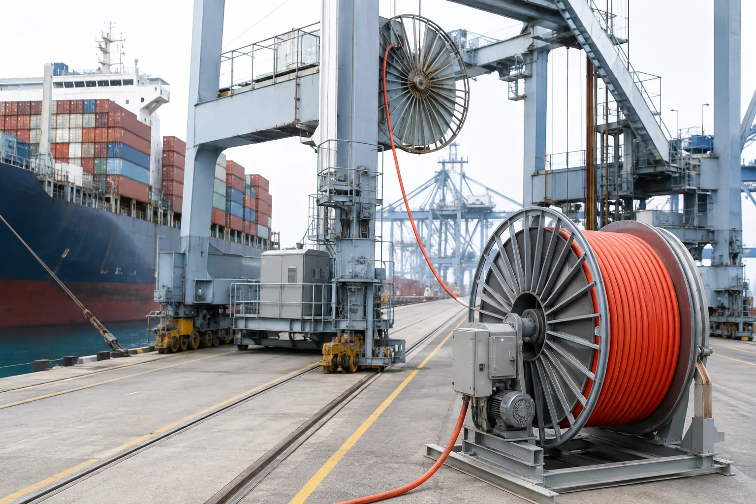
- Ship-to-shore and container-crane main power reels.
- Portal cranes and ship unloaders.
- Stackers, reclaimers and bulk-material handling machines.
- Heavy mobile mining equipment using motorized cable drums.
- Moving power-and-data routes using the confirmed 12- or 24-fibre option.
Selection and Installation Checks
Provide the drum diameter, deflection-pulley diameter, S-bend geometry, travel direction, maximum speed, acceleration, suspended length, mounting height and expected torsion. The reel value, pulley value and S-bend value are different; using only the smallest number can understate the required path geometry.
For one-plane flat movement, compare the NTSFLCGEWOEU flat reeling cable. For another screened round reel construction, review the R-(N)TSCGEWÖU reeling cable; neither should be treated as equivalent without a full application check.
Reference designation cross-reference
Enquiries for this cable arrive under several reference names from the same reeling family. What changes between them is the variant, not the cable type.
| Reference designation | TEBAOFLEX designation and build | Rated voltage | What the reference name marks |
|---|---|---|---|
| TENAX-T / NTSCGEWOEU | NTSCGEWOEU crane reeling cable | 3.6/6 to 12/20 kV | The standard reeling build of the family |
| TENAX-TT / NTSCGEWOEU | NTSCGEWOEU with twist protection | 3.6/6 to 12/20 kV | Twist protection for guiding systems that deflect in several planes, or a reel axis in the direction of travel |
| TENAX-TZ / NTSCGEWOEU | NTSCGEWOEU with strain relief | 3.6/6 to 12/20 kV | Strain relief and improved flexibility for increased mechanical tension |
| TENAX-TS / NTSCGEWOEU | NTSCGEWOEU, 15 N/mm² tensile reference | 3.6/6 to 12/20 kV | The 15 N/mm² long-term tensile limit on the phase-conductor cross-section |
| TENAX-TTS / NTSCGEWOEU | NTSCGEWOEU, 20 N/mm² tensile reference | 3.6/6 to 12/20 kV | The 20 N/mm² long-term tensile limit; dynamic peaks not above 25 N/mm² |
| TENAX-TTS LWL / NTSCGEWOEU with FO | NTSCGEWOEU with integrated optical fibres | 3.6/6 to 12/20 kV | LWL marks the integrated fibre element; state fibre count and type |
For the full list of reference designations and the TEBAOFLEX build each one maps to, see the mining cable designation cross-reference.
Trademark note: TENAX®, TROMMELFLEX®, FELTOFLEX® and SCHRÄM® are trademarks of their respective owners, and TEBAOFLEX is neither affiliated with those companies nor reselling their cable. What we supply is the equivalent construction: we manufacture to the same VDE type designation and published construction, and every designation listed here can be quoted and supplied as a TEBAOFLEX build. Each TEBAOFLEX build is made to the standards and construction confirmed for the order.
NTSCGEWOU / (N)TSCGEWÖU Specifications
Use these family-level values for preliminary selection. The quotation and approved datasheet must identify the final conductor arrangement, dimensions and project-specific duty.
| Parameter | Verified family data | Selection note |
|---|---|---|
| Rated voltage | 3.6/6 kV; 6/10 kV; 8.7/15 kV; 12/20 kV | Match the network and equipment insulation level. |
| Travel speed | Up to 180 m/min | Also provide acceleration and route geometry. |
| Minimum bending radius — reel | 12 × cable outside diameter | Use for the cable drum path. |
| Minimum bending radius — deflection pulley | 15 × cable outside diameter | Check every diversion roller in the route. |
| Minimum bending radius — S-type direction change | 20 × cable outside diameter | Applies where the cable reverses bend direction. |
| Ambient temperature, flexing | -30°C to +80°C | Confirm start-up and operating temperature. |
| Ambient temperature, fixed | -50°C to +80°C | Fixed value does not replace the flexing limit. |
| Insulation system | Screened EPR-MV sandwich construction | Confirm termination compatibility. |
| Reinforcement | High-tensile anti-twisting braid between sheath layers | Reel alignment and twist control remain necessary. |
| Fibre-optic option | 12 or 24 fibres in loose tubes | Specify fibre count and termination interface. |
| Outer sheath | High-wear synthetic rubber | Confirm the actual environmental exposure at RFQ. |
NTSCGEWOU+FO / (N)TSCGEWÖU+FO Constructions Built by TEBAOFLEX
These fibre-optic constructions have been produced to customer orders, as printed on the cable sheath. Diameter, weight and fibre test values are confirmed on the order datasheet.
| Construction | Rated voltage | Power and earth conductors | Control element | Fibre element |
|---|---|---|---|---|
| NTSCGEWOU+FO 3.6/6 kV 3×25+2×25/2+18FO | 3.6/6 kV | 3×25 mm² + 2×25/2 mm² | — | 18 fibres, single-mode 9/125 µm |
| NTSCGEWOU+FO 6/10 kV 3×50+2×35/2+12FO | 6/10 kV | 3×50 mm² + 2×35/2 mm² | — | 12 fibres, multimode 62.5/125 µm |
| NTSCGEWOU+FO 6/10 kV 3×70+2×35/2+12FO | 6/10 kV | 3×70 mm² + 2×35/2 mm² | — | 12 fibres, multimode 62.5/125 µm |
| NTSCGEWOU+FO 8.7/15 kV 3×35+3×35/3+(20×2.5)C+24FO | 8.7/15 kV | 3×35 mm² + 3×35/3 mm² | 20×2.5 mm² | 24 fibres, single-mode 9/125 µm |
| NTSCGEWOU+FO 8.7/15 kV 3×70+2×35/2+(20×2.5)C+24FO | 8.7/15 kV | 3×70 mm² + 2×35/2 mm² | 20×2.5 mm² | 24 fibres, single-mode 9/125 µm |
Information Required for Final Sizing
State the voltage, phase-conductor size, earth-core arrangement, installed length, current/load data, drum and pulley dimensions, speed, acceleration, mounting height, bend path, torsion, fibre requirement and environmental conditions. Dimensions, mass, electrical values and tensile limits must come from the approved order-specific datasheet.
Standards and Documentation
The published construction data supports the following technical reference. Keep standards, tests and project documentation separate when preparing the purchase specification.
| Reference | Relationship to this cable page |
|---|---|
| IEC 60228 | Class 5 flexible copper conductor reference. |
Order-Specific Documents to Request
- Approved cable construction drawing and conductor/core schedule.
- Routine medium-voltage electrical test report for the ordered voltage and size.
- Dimensional and conductor-resistance records for the supplied batch.
- For FO versions: fibre type, count, tube identification and continuity test results.
The model designation does not by itself confirm a project approval, certificate or compatibility with an existing reel. List the required inspection, marking and documentation scope in the enquiry.
Related cable options
Compare these cable options by service combination, movement, load, voltage and transmission requirement.
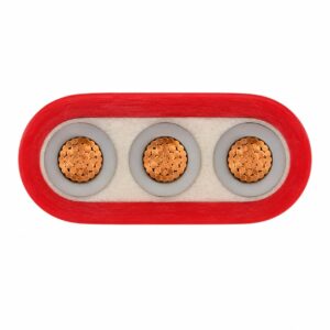
NTSFLCGEWOEU Medium Voltage Flat Reeling Cable
A related cable option for a different application or duty profile.
View product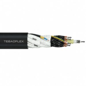
SYSLTOE FO Basket Spreader Cable 0.6/1 kV
A related cable option for a different application or duty profile.
View product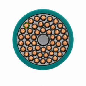
TRA Anti-Torsion PUR Reeling Cable 0.6/1 kV
A related cable option for a different application or duty profile.
View productRequest a cable recommendation and quotation
Send the required services, cable length, mechanical duty, environment, termination and quantity. Our team will review the application before quoting.
- Include the product name or SKU plus the required cable length and quantity.
- Attach a specification, drawing or data sheet when available.