










(N)TSFLCGEWÖU-FO / (N)TSFLCGEWOEU-LWL (3.6/6–12/20 kV) Medium-Voltage Optical & Hybrid Flat Reeling Cable
(N)TSFLCGEWÖU-FO ((N)TSFLCGEWOEU-LWL / NTSFLCGEWOEU+FO) is a medium-voltage flat electro-optical reeling cable engineered with reference to DIN VDE 0250-813 across 3.6/6 kV, 6/10 kV, 8.7/15 kV and 12/20 kV systems, combining triple-extruded 3GI3 EPR screened power cores (3×35 to 3×120 mm²), split concentric or independent earth conductors, 6 to 24 GI 50/125, GI 62.5/125 or SM 9/125 optical fibres, and optional 2.5 mm² control bundles in a 5GM5 rubber flat sheath.
(N)TSFLCGEWÖU-FO / (N)TSFLCGEWOEU-LWL medium-voltage flat electro-optical reeling cable transmits crane drive power (3.6/6 kV, 6/10 kV, 8.7/15 kV and 12/20 kV) together with optical PLC/telemetry links and optional 2.5 mm² pilot/control circuits inside one low-height flat profile rated for 120 to 180 m/min monospiral drum travel and 15 N/mm² copper tensile load.
On modern automated ship-to-shore (STS) cranes, rail-mounted gantry (RMG) cranes and bulk stacker-reclaimers, narrow radial monospiral reels stack flat layers directly on top of one another to save sill-beam width. Standard power-only (N)TSFLCGEWÖU leaves crane automation without optical immunity, whereas retrofitting a round electro-optical cable changes drum flange geometry and roller guides. TEBAOFLEX builds both DIN VDE 0250-813 split-earth (/4E) optical flat cables and slot-matched hybrid layouts—such as 8.7/15 kV 3×120 + 1×70 + 12×2.5 + 12FO at 34.5 x 120.0 mm—so replacement cables drop directly into existing monospiral drum slots and quay trenches.
Select (N)TSFLCGEWÖU-FO when a single-plane monospiral reel or heavy festoon requires medium-voltage power plus optical fibres or mixed control cores. For power-only flat reeling up to 6/10 kV see (N)TSFLCGEWÖU, for round torsional drum reeling choose (N)TSCGEWÖU+FO, and for Japanese 3.3/6.6 kV flat optical drums review FG-H-3PNCT.
When replacing legacy Japanese crane BOM specification RIKEN RNEDAFLAT-XT 8.7/15 kV 3×120 + 70 + 12×2.5 + 12FO (drawing SP12-31-0117), see our dedicated TF-FLC-XT 8.7/15 kV 3×120+70+12×2.5+12FO slot-matched crane drum replacement schedule.
Explore the port, crane reeling and festoon cable range for related configurations.
(N)TSFLCGEWÖU-FO / -LWL Flat Electro-Optical Cable Construction
(N)TSFLCGEWÖU-FO is vulcanized on TEBAOFLEX flat-cable lines with parallel single-plane core alignment to eliminate inter-core twisting under radial layer stacking: [Class 5 Tinned Cu Phase Conductors] -> [Triple-Extruded Inner Semi-Con + 3GI3 EPR + Strippable Outer Semi-Con] -> [Split Concentric Cu/Earth Screen (/4E) or Independent PE Core] + [ETFE-Buffered 6-24FO Optical Subunit (+/- 2.5 mm² Control Bundle)] -> [Single-Plane Parallel Lay-Up] -> [5GM5 Brick-Red or Black Polychloroprene Flat Sheath].
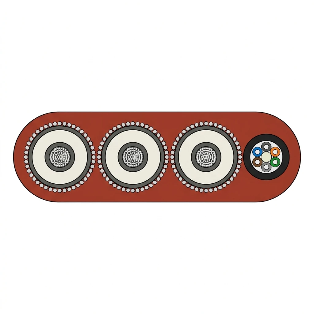
| Component | Material and construction |
|---|---|
| 1. Phase & earth conductors | Electrolytic tinned fine-stranded copper to IEC 60228 Class 5 (35 to 120 mm² phase sections; concentric /4E split earth or dedicated Class 5 PE core). |
| 2. Triple-extruded MV core dielectric | Simultaneously vulcanized inner semi-conductive elastomer, 3GI3 ozone-resistant EPR insulation (DIN VDE 0207-20) and cold-strippable outer semi-conductive screen for stress-free MV terminations. |
| 3. Metallic phase earth screen | Helical / braided tinned copper screen wires distributed across the three MV cores (/3E or /4E) or individual copper-tape/braid phase screens paired with an insulated PE conductor. |
| 4. Optical fibre subunit (-FO / -LWL) | Non-metallic FRP central strength element surrounded by 7YI1 (ETFE) loose buffer tubes housing 6, 12, 18 or 24 multimode GI 50/125 (OM2/OM3), GI 62.5/125 (OM1) or single-mode 9/125 (ITU-T G.652.D / G.657.A2) fibres under an elastomeric inner jacket. |
| 5. Optional 2.5 mm² control bundle (TF-FLC hybrids) | 6 to 12 fine-stranded tinned copper 2.5 mm² EPR-insulated control cores (0.6/1 kV, AC routine tested at 3.5 kV / 5 min) cabled with or alongside the optical subunit to match existing crane reel slot widths. |
| 6. Flat outer sheath | Heavy-duty vulcanized polychloroprene rubber compound type 5GM5 (DIN VDE 0207-21), brick-red or black, oil-resistant to IEC 60811-404, UV/seawater-resistant and flame-retardant to IEC 60332-1-2. |
(N)TSFLCGEWÖU-FO & TF-FLC Designation Breakdown
- (N)TSFL: Engineered with reference to DIN VDE 0250-813 (N): heavy drum reeling service (T, S) in a single-plane flat cable geometry (FL, Flachleitung)
- C: Concentric tinned-copper earth / metallic phase screen over each medium-voltage power core
- GE: 3GI3 EPR elastomer insulation (G) with triple-extruded inner and strippable outer semi-conductive field-control layers (E)
- WÖU (WOEU): Weather-resistant (W), mineral-oil-resistant (Ö/OE) and flame-retardant (U) 5GM5 heavy-duty rubber outer sheath
- -FO / -LWL (+FO): Integrated optical-fibre subunit (Lichtwellenleiter) containing 6 to 24 GI 50/125, GI 62.5/125 or SM 9/125 fibres
- TF-FLC Hybrid: Custom slot-matched flat lay-up integrating 3 MV phase cores + 1 PE core + 6–12x2.5 mm² control cores + 12–24FO subunit
(N)TSFLCGEWÖU-FO Monospiral Crane & Port Reeling Applications
(N)TSFLCGEWÖU-FO and TF-FLC hybrid flat cables are engineered for single-plane bending on narrow radial monospiral reels and heavy crane festoons.
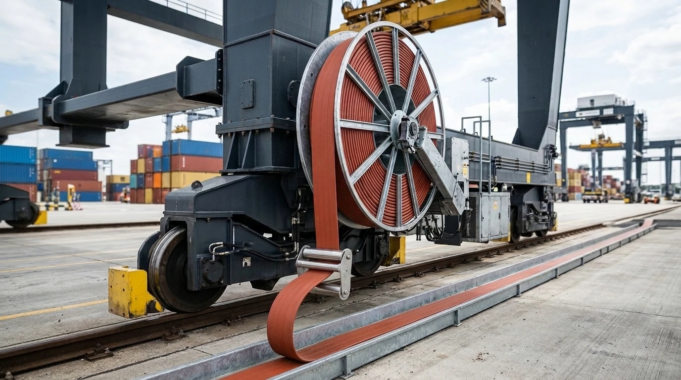
- Automated ship-to-shore (STS) quay cranes and rail-mounted gantry (RMG / ASC) cranes winding vertically onto narrow sill-beam monospiral drums into slotted quay trenches.
- 8.7/15 kV and 12/20 kV port terminal feeders where higher medium voltage cuts phase cross-section and drum deadweight while carrying redundant 12FO or 24FO terminal automation links.
- Drop-in slot-matched replacement of custom imported 8.7/15 kV 3x120+1x70+12x2.5+12FO flat crane reeling cables without altering drum flange spacing or deflection rollers.
- Bulk-material stacker-reclaimers, ship unloaders, steelworks charging cranes and dam gantry hoists requiring zero-EMI optical PLC feedback alongside MV drives.
- Heavy-duty medium-voltage catenary festoon loops requiring smaller single-plane bending radii than equivalent round MV cables.
(N)TSFLCGEWÖU-FO vs Power-Only Flat, Round & JCS Reeling Cables
| Cable series | Profile & reel type | Voltage & data integration | Primary selection boundary |
|---|---|---|---|
| (N)TSFLCGEWÖU-FO / TF-FLC (this page) | Flat — narrow monospiral drum or heavy festoon (0°/m torsion) | 3.6/6 to 12/20 kV + 6–24FO (+/- 2.5 mm² control cores) | Single-plane crane reels needing MV power plus optical fibres or slot-matched control hybrids |
| (N)TSFLCGEWÖU (power-only) | Flat — monospiral drum or festoon | 3.6/6 and 6/10 kV power + earth only (0 FO) | Standard flat MV power reels where crane telemetry runs on a separate festoon or wireless link |
| (N)TSCGEWÖU / (N)TSCGEWÖU+FO | Round — cylindrical multi-groove or monospiral drum (±25°/m torsion) | 3.6/6 to 20/35 kV power (+/- FO) | High-speed STS boom/gantry drums with roller deflection in multiple planes or torsional twist |
| FG-H-3PNCT / FG-3PNCT | Flat — Japanese-design monospiral crane reel | 3.3 kV and 6.6 kV + 6–12 GI 50/125 fibres | Japanese-built 3.3/6.6 kV STS/RTG cranes engineered to JCS / Japanese Electrical Equipment standards |
Flat medium-voltage reeling cables bend strictly across their minor axis (height H) and must never be subjected to axial torsion; if the cable path twists between horizontal and vertical sheaves, specify round (N)TSCGEWÖU+FO instead.
(N)TSFLCGEWÖU-FO & Custom Slot-Matched Hybrid RFQ Checklist
- System voltage U0/U and Um (3.6/6 kV, 6/10 kV, 8.7/15 kV or 12/20 kV) plus required routine / witnessed FAT AC test voltage.
- Phase, earth and control conductor cross-sections (for example 3x95+4x50/4E+12FO or custom 3x120+1x70+12x2.5+12FO).
- Optical fibre count and grade: 6, 12, 18 or 24 fibres in GI 50/125 (OM2/OM3), GI 62.5/125 (OM1) or SM 9/125 (ITU-T G.652.D / G.657.A2).
- Existing monospiral drum inner barrel diameter, clear flange-to-flange slot width (mm), stacked layer count and travel speed (m/min).
- Preferred 5GM5 outer sheath colour (brick-red or black), ambient temperature extremes and trench / roller guide geometry.
- Required continuous drum length(s) (MOQ 50 m; manufacturing lead time 7 to 45 working days) and delivery port.
Related selection resources
- Port, crane reeling and festoon cable catalog
- Engineering guide: medium-voltage monospiral vs cylindrical crane reeling cable selection
- Engineering guide: measuring drum slot width and identifying replacement reeling cables
- (N)TSFLCGEWÖU 3.6/6 & 6/10 kV power-only flat crane reeling cable
- (N)TSCGEWÖU / (N)TSCGEWÖU+FO round torsional MV crane reeling cable
- 3PNCT, H-3PNCT & FG-H-3PNCT 3.3–6.6 kV Japanese-standard flat & optical reeling cables
(N)TSFLCGEWÖU-FO / -LWL Flat Optical Reeling Cable FAQ
Can (N)TSFLCGEWÖU-FO combine 8.7/15 kV power, 12x2.5 mm² control cores and 12 optical fibres in one flat cable?
Yes. TEBAOFLEX manufactures custom slot-matched TF-FLC builds—such as 8.7/15 kV 3x120 + 1x70 + 12x2.5 + 12FO (GI 50/125 or SM 9/125) at nominal 34.5 x 120.0 mm—to fit existing monospiral crane drum slots.
What routine AC withstand test voltage applies to 8.7/15 kV (N)TSFLCGEWOEU-FO cables?
24 kV AC for 5 minutes is applied as the standard routine factory dielectric test with reference to DIN VDE 0250-813, while 21 kV or 30.5 kV 5-minute client-witnessed FAT protocols are also supported on request.
What minimum dynamic bending radius is required for (N)TSFLCGEWÖU-FO on a monospiral crane reel?
415 to 620 mm depending on cable height H (approximately 15 x H in dynamic monospiral reeling, or 500 mm on slot-matched 34.5 mm high 8.7/15 kV hybrid builds), bending strictly in a single plane with 0°/m torsion.
Which optical fibre types can be integrated inside (N)TSFLCGEWÖU-FO / (N)TSFLCGEWOEU-LWL?
6, 12, 18 or 24 fibres housed in crush-resistant ETFE (7YI1) buffer tubes, selectable in multimode GI 50/125 µm (≤ 2.8 dB/km at 850 nm), GI 62.5/125 µm, or single-mode 9/125 µm ITU-T G.652.D / G.657.A2.
What are the minimum order quantity and lead time for (N)TSFLCGEWÖU-FO flat optical reeling cables?
50 m is the minimum order quantity (MOQ), with a factory production lead time of 7 to 45 working days depending on voltage tier and custom hybrid lay-up tooling.
(N)TSFLCGEWÖU-FO Technical Ratings, Standard & Hybrid Size Schedules
(N)TSFLCGEWÖU-FO Key Voltage, Optical & Mechanical Parameters
- 3.6/6 to 12/20 kV flat profile: Single-plane lay-up for narrow monospiral crane reels where round drums exceed sill-beam clearance
- Triple-extruded 3GI3 EPR dielectric: Inner semi-conductive screen, EPR insulation and strippable outer semi-con layer on every MV phase core
- 6 to 24FO ETFE optical subunit: Crush-resistant 7YI1 ETFE micro-tubes housing GI 50/125, GI 62.5/125 or ITU-T G.652.D / G.657.A2 SM 9/125 fibres
- Slot-matched control + FO hybrids: Custom 8.7/15 kV and 6/10 kV flat builds combining 3 phase cores, 1 PE core, 6–12x2.5 mm² control cores and 12–24FO
- Project manufacturing: Brick-red or black 5GM5 polychloroprene sheath supplied from MOQ 50 m in 7 to 45 working days
| Parameter | Value |
|---|---|
| Rated voltage | 3.6/6 kV, 6/10 kV, 8.7/15 kV and 12/20 kV U0/U (Um 7.2, 12, 18 and 24 kV AC) |
| Conductor and MV screen | IEC 60228 Class 5 tinned copper; triple-extruded semi-con + 3GI3 EPR + tinned Cu phase screens |
| Optical and hybrid options | 6 to 24 fibres (GI 50/125, GI 62.5/125 or SM 9/125 ITU-T G.652.D / G.657.A2); optional 6x2.5 to 12x2.5 mm2 control cores |
| Outer sheath compound | 5GM5 polychloroprene heavy-duty flat rubber sheath in brick-red or black, oil and flame resistant |
| Supply terms | MOQ 50 m with 7 to 45 working days manufacturing lead time; custom slot-width matching supported |
| Mechanical reeling limits | 15 N/mm² Cu tensile load (up to 7.9 kN reinforced hybrid); up to 120–180 m/min travel; lateral load up to 4.9 kN/m; 0°/m torsion |
| Temperature range | 90 °C conductor (250 °C 5 s short-circuit); -35 °C to +80 °C dynamic reeling; -50 °C to +80 °C fixed |
(N)TSFLCGEWÖU-FO Voltage, Thermal, Mechanical and Optical Ratings
| Parameter | 3.6/6 kV Tier | 6/10 kV Tier | 8.7/15 kV Tier | 12/20 kV Tier |
|---|---|---|---|---|
| Nominal voltage U0/U (kV) | 3.6/6 kV | 6/10 kV | 8.7/15 kV | 12/20 kV |
| Max. operating voltage Um AC / DC (kV) | 4.2/7.2 kV AC / 5.4/10.8 kV DC | 6.9/12 kV AC / 9.0/18 kV DC | 10.4/18 kV AC / 13.5/27 kV DC | 13.9/24 kV AC / 18.0/36 kV DC |
| 5-min AC routine withstand voltage (kV) | 11 kV (DIN VDE 0250-813) | 17 kV (DIN VDE 0250-813) | 24 kV (21–30.5 kV client FAT options) | 29 kV (DIN VDE 0250-813) |
| Conductor & dielectric system | IEC 60228 Class 5 tinned Cu; triple-extruded inner semi-con + 3GI3 EPR + strippable outer semi-con | Same triple-extruded 3GI3 EPR system | Same triple-extruded 3GI3 EPR system | Same triple-extruded 3GI3 EPR system |
| Temperature ratings (°C) | Conductor 90 °C continuous / 250 °C short-circuit (5 s); dynamic reeling -35 °C to +80 °C; fixed -50 °C to +80 °C | Same thermal envelope | Same thermal envelope | Same thermal envelope |
| Mechanical reeling limits | Max. Cu tensile load 15 N/mm²; travel speed up to 120 m/min (180 m/min controlled); lateral load ≤ 4.9 kN/m; single-plane bending only (0°/m torsion) | Same mechanical envelope | Same mechanical envelope | Same mechanical envelope |
| Optical fibre subunit (-FO / -LWL) | 6, 12, 18 or 24 fibres in ETFE (7YI1) buffer tubes: GI 50/125 µm (≤ 2.8 dB/km @ 850 nm, ≥ 400 MHz·km), GI 62.5/125 µm (≤ 3.3 dB/km @ 850 nm), or SM 9/125 µm ITU-T G.652.D / G.657.A2 (≤ 0.40 dB/km @ 1310 nm, ≤ 0.30 dB/km @ 1550 nm) | Same optical options | Same optical options | Same optical options |
(N)TSFLCGEWÖU-FO / -LWL Standard Optical Flat Reeling Schedule (3.6/6–12/20 kV)
| Model & configuration (n x mm² + FO) | Voltage U0/U (kV) | Nominal H x W (mm) | Max. H x W (mm) | Min. dynamic bend radius (mm) | Approx. weight (kg/km) | Max. Cu tensile load at 15 N/mm² (N) | Max. DC resistance at 20 °C (Ω/km) | 1-layer reel ampacity at 30 °C (A) | 1 s short-circuit Isc (kA) | Next step |
|---|---|---|---|---|---|---|---|---|---|---|
| (N)TSFLCGEWOEU-FO 3.6/6 kV 3x35+4x25/4E+6/12FO | 3.6/6 | 26.0 × 86.0 | 27.5 × 88.5 | 415 | 3,700 | 1,575 | 0.565 | 130 | 5.01 | Request this size |
| (N)TSFLCGEWOEU-FO 3.6/6 kV 3x50+4x25/4E+6/12FO | 3.6/6 | 28.5 × 90.0 | 30.5 × 92.5 | 450 | 4,350 | 2,250 | 0.393 | 162 | 7.15 | Request this size |
| (N)TSFLCGEWOEU-FO 3.6/6 kV 3x70+4x35/4E+6/12FO | 3.6/6 | 30.2 × 100.0 | 31.7 × 102.7 | 476 | 5,590 | 3,150 | 0.277 | 200 | 10.01 | Request this size |
| (N)TSFLCGEWOEU-FO 3.6/6 kV 3x95+4x50/4E+6/12FO | 3.6/6 | 32.0 × 107.8 | 33.6 × 110.3 | 504 | 6,720 | 4,275 | 0.210 | 241 | 13.59 | Request this size |
| (N)TSFLCGEWOEU-FO 6/10 kV 3x35+4x25/4E+6/12FO | 6/10 | 26.8 × 89.0 | 28.5 × 91.7 | 428 | 3,910 | 1,575 | 0.565 | 130 | 5.01 | Request this size |
| (N)TSFLCGEWOEU-FO 6/10 kV 3x50+4x25/4E+6/12FO | 6/10 | 29.3 × 96.5 | 31.0 × 99.1 | 465 | 4,810 | 2,250 | 0.393 | 162 | 7.15 | Request this size |
| (N)TSFLCGEWOEU-FO 6/10 kV 3x70+4x35/4E+6/12FO | 6/10 | 31.0 × 103.4 | 32.5 × 105.9 | 488 | 5,800 | 3,150 | 0.277 | 200 | 10.01 | Request this size |
| (N)TSFLCGEWOEU-FO 6/10 kV 3x95+4x50/4E+6/12FO | 6/10 | 32.9 × 111.0 | 34.4 × 113.5 | 516 | 6,940 | 4,275 | 0.210 | 241 | 13.59 | Request this size |
| (N)TSFLCGEWOEU-FO 6/10 kV 3x120+4x70/4E+12/24FO | 6/10 | 36.5 × 118.5 | 38.5 × 122.0 | 578 | 8,320 | 5,400 | 0.164 | 282 | 17.16 | Request this size |
| (N)TSFLCGEWOEU-FO 8.7/15 kV 3x35+4x25/4E+6/12FO | 8.7/15 | 30.8 × 99.4 | 32.3 × 101.9 | 485 | 4,630 | 1,575 | 0.565 | 138 | 5.01 | Request this size |
| (N)TSFLCGEWOEU-FO 8.7/15 kV 3x50+4x25/4E+6/12FO | 8.7/15 | 31.5 × 105.4 | 33.5 × 107.9 | 500 | 5,400 | 2,250 | 0.393 | 172 | 7.15 | Request this size |
| (N)TSFLCGEWOEU-FO 8.7/15 kV 3x70+4x35/4E+12FO | 8.7/15 | 32.7 × 112.2 | 34.5 × 114.7 | 518 | 6,460 | 3,150 | 0.277 | 212 | 10.01 | Request this size |
| (N)TSFLCGEWOEU-FO 8.7/15 kV 3x95+4x50/4E+12FO | 8.7/15 | 36.5 × 118.0 | 38.5 × 121.5 | 578 | 7,680 | 4,275 | 0.210 | 255 | 13.59 | Request this size |
| (N)TSFLCGEWOEU-FO 8.7/15 kV 3x120+4x70/4E+12/24FO | 8.7/15 | 38.8 × 124.0 | 40.8 × 128.0 | 612 | 8,950 | 5,400 | 0.164 | 297 | 17.16 | Request this size |
| (N)TSFLCGEWOEU-FO 12/20 kV 3x50+4x25/4E+12FO (ref.) | 12/20 | 35.0 × 114.0 | 37.0 × 118.0 | 550 | 6,150 | 2,250 | 0.393 | 175 | 7.15 | Request this size |
| (N)TSFLCGEWOEU-FO 12/20 kV 3x95+4x50/4E+12/24FO (ref.) | 12/20 | 39.5 × 127.0 | 41.5 × 131.0 | 620 | 8,450 | 4,275 | 0.210 | 258 | 13.59 | Request this size |
(N)TSFLCGEWÖU-FO Custom Slot-Matched Power + Control + Optical Hybrid Schedule (TF-FLC)
| Custom hybrid part ref. & layout | Voltage U0/U (kV) | Element lay-up sequence (slot-matched) | Nominal H x W (max. mm) | Min. bend radius (mm) | Approx. weight (kg/km) | Max. pulling / working tension & lateral load | Electrical & optical acceptance | Next step |
|---|---|---|---|---|---|---|---|---|
| (N)TSFLCGEWOEU-FO / TF-FLC-8.7/15 3x120+1x70+12x2.5+12FO (GI 50/125 or SM 9/125) | 8.7/15 | L1 (120) · PE (70) · L2 (120) · [12×2.5 Ctrl + 12FO Subunit] · L3 (120) | 34.5 × 120.0 (max. 38.4 × 123.8) | 500 | 9,750 | Max. 7.9 kN (reinforced) / 2.6 kN working; lateral ≤ 4.9 kN/m | 120 mm² IEC 60228 Cl.5 (≤ 0.164 Ω/km); 2.5 mm² (3.5 kV/5 min); MV AC test 24 kV/5 min (21 kV FAT supported); GI 50/125 ≤ 3.0 dB/km @ 850 nm | Request this size |
| (N)TSFLCGEWOEU-FO / TF-FLC-8.7/15 3x70+1x35+12x2.5+12FO (GI 50/125 or SM 9/125) | 8.7/15 | L1 (70) · PE (35) · L2 (70) · [12×2.5 Ctrl + 12FO Subunit] · L3 (70) | 31.5 × 108.0 (max. 34.5 × 112.0) | 480 | 6,950 | Max. 4.8 kN / 1.6 kN working; lateral ≤ 4.9 kN/m | 70 mm² Cl.5 (≤ 0.277 Ω/km); MV AC test 24 kV/5 min; 12FO GI 50/125 or SM 9/125 | Request this size |
| (N)TSFLCGEWOEU-FO / TF-FLC-6/10 3x95+1x50+12x2.5+12FO (GI 50/125 or SM 9/125) | 6/10 | L1 (95) · PE (50) · L2 (95) · [12×2.5 Ctrl + 12FO Subunit] · L3 (95) | 32.5 × 112.0 (max. 35.5 × 116.0) | 490 | 7,820 | Max. 6.2 kN / 2.1 kN working; lateral ≤ 4.9 kN/m | 95 mm² Cl.5 (≤ 0.210 Ω/km); MV AC test 17 kV/5 min; 12FO GI 50/125 or SM 9/125 | Request this size |
| (N)TSFLCGEWOEU-FO / TF-FLC-6/10 3x50+3x25/3E+6x2.5+12FO (GI 50/125 or SM 9/125) | 6/10 | L1 (50+25/3E) · L2 (50+25/3E) · [6×2.5 Ctrl + 12FO] · L3 (50+25/3E) | 29.5 × 98.0 (max. 32.0 × 102.0) | 450 | 5,240 | Max. 3.4 kN / 1.1 kN working; lateral ≤ 4.9 kN/m | 50 mm² Cl.5 (≤ 0.393 Ω/km); concentric /3E split earth saves 8–10 mm reel slot width | Request this size |
Standard 1-layer reel ampacities at 30 °C ambient are derived with reference to DIN VDE 0298-4; apply multi-layer drum derating factors according to stacked layer count and ambient duty.
Custom TF-FLC hybrid dimensions, weights and element lay-up sequences are engineering reference values for made-to-order monospiral drum replacements; exact slot-matched height, width and core sequence are confirmed on the approval drawing issued with every quotation.
8.7/15 kV cores undergo routine 5-minute AC withstand testing at 24 kV with reference to DIN VDE 0250-813 (or 21 kV / 5 min and 30.5 kV / 5 min when requested for project FAT alignment).
Minimum order quantity is 50 m and manufacturing lead time is 7 to 45 working days.
ASCII part references: (N)TSFLCGEWOEU-FO; NTSFLCGEWOEU+FO; (N)TSFLCGEWOU-LWL; NTSFLCGEWOEU-LWL; 8.7/15kV flat reeling cable 3x120+70+12x2.5+12FO 50/125; TF-FLC-8.7/15 3x120+1x70+12x2.5+12FO; WGF-D flat fibre optic reeling cable.
(N)TSFLCGEWÖU-FO Standards & Factory Routine Testing
| Standard or specification | Application |
|---|---|
| DIN VDE 0250-813 (reference construction) | Design, triple-extruded EPR insulation wall thickness and AC routine test voltages (11 / 17 / 24 / 29 kV) for medium-voltage trailing and reeling cables. |
| DIN VDE 0298-3 / DIN VDE 0298-4 | Mechanical installation rules (single-plane bend radius, 15 N/mm² tensile load) and current-carrying capacity derating on crane reels. |
| DIN VDE 0207-20 / DIN VDE 0207-21 | 3GI3 EPR medium-voltage insulation compound and 5GM5 heavy-duty polychloroprene sheath compound requirements. |
| IEC 60228 / IEC 60794-1-2 | Class 5 tinned flexible copper conductor DC resistance limits and optical attenuation / mechanical verification on completed electro-optical cables. |
| IEC 60332-1-2 / IEC 60811-404 | Single-cable vertical flame propagation test and mineral-oil immersion resistance of the outer flat rubber sheath. |
Certifications and document support
TEBAOFLEX ISO quality assurance and MV dielectric / OTDR factory routine testing
DIN Media — DIN VDE 0250-813 / 0298-4 / 0207 standards reference
IEC Webstore — IEC 60228, IEC 60794 and IEC 60332 test standards
Related cable options
Compare these cable options by service combination, movement, load, voltage and transmission requirement.
TF-FLC-XT 8.7/15 kV 3×120+70+12×2.5+12FO Flat Reeling Cable (RIKEN RNEDAFLAT-XT Replacement)
A related cable option for a different application or duty profile.
View product
NTSFLCGEWOEU Medium Voltage Flat Reeling Cable
A related cable option for a different application or duty profile.
View product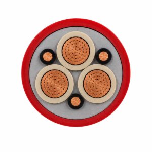
NTSCGEWOU / (N)TSCGEWÖU+FO Medium Voltage Crane Reeling Cable
A related cable option for a different application or duty profile.
View productRequest a cable recommendation and quotation
Send the required services, cable length, mechanical duty, environment, termination and quantity. Our team will review the application before quoting.
- Include the product name or SKU plus the required cable length and quantity.
- Attach a specification, drawing or data sheet when available.