










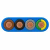

S07BBH2-F / S1BBH2-F Flat Drinking Water Pump Cable
S07BBH2-F and S1BBH2-F are flat drinking-water pump cables with flexible Class 5 copper conductors, EPR insulation and a blue EM6-type EPR sheath.
- S07BBH2-F: 450/750 V; S1BBH2-F: 0.6/1 kV
- EPR core insulation and a blue EM6-type EPR sheath
- Class 5 plain copper conductors
- 90 °C maximum conductor temperature
- Flat single-row geometry; separate height and width limits
S07BBH2-F and S1BBH2-F are flat drinking-water pump cables with flexible Class 5 copper conductors, EPR insulation and a blue EM6-type EPR sheath. Their insulated cores lie side by side in one row. S07BBH2-F is rated 450/750 V, while S1BBH2-F is rated 0.6/1 kV.
Flat geometry is useful where the pump, well casing or equipment entry provides a narrow installation envelope. Each table therefore lists minimum and maximum height and width separately. Check both dimensions against the entry profile, seal compression range, rising main and other equipment sharing the route.
The two voltage families have separate configuration tables and test conditions. Three-core and four-core protective-earth configurations are available in the listed sizes. Match the G designation and phase arrangement to the motor wiring diagram, then use the associated mass, tensile-force and current data for the route design.
Plan the bend direction before positioning supports. Allow the specified radius at the entry, avoid twisting the broad face through a tight turn and provide strain relief along the riser. The electrical cable is supported independently of the pump lifting arrangement. Send the available height and width, entry drawing, motor duty, cable length and water-contact requirements with the enquiry. Water depth and water-temperature limits are confirmed for the project after enquiry. Round-entry alternatives are covered by the companion S07BB-F and S1BB-F family.
Construction
Cable layers are listed from the conductor to the outer sheath.
| Layer | Construction |
|---|---|
| Conductor | Plain Class 5 flexible copper. |
| Insulation | Individual EPR core insulation. |
| Flat assembly | Three or four insulated conductors laid side by side in one row; the selected G configuration includes green/yellow PE. |
| Outer sheath | Blue EM6-type EPR rubber, with no metallic screen or armour. |
Applications
Use this construction for drinking-water pump motors in narrow well and equipment routes. Match the cable to the actual equipment, route and water medium before selecting the final configuration.

- Use height and width limits to check clearance; a flat cable does not have one round outside diameter.
- Choose the cable entry profile and bend direction together with the pump supplier.
- Support the cable along the riser and keep lifting loads on the mechanical lifting system.
Use a supported route under medium mechanical stress. Exclude explosion-hazard locations and water containing more than 0.5 mg/l chlorine for this construction. Review other aggressive water compositions individually.
Flat cable installation envelope
| Selection point | Design input |
|---|---|
| Clearance | Compare the maximum height and width with the pump entry and well casing. |
| Bend orientation | Plan the broad-face orientation and specified radius before fixing supports. |
| Entry sealing | Use an entry designed for the selected flat profile. |
| Support | Provide independent support along the riser and separate pump lifting equipment. |
Related selection resources
Specifications
| Parameter | Value |
|---|---|
| Rated voltage U₀/U | S07BBH2-F: 450/750 V; S1BBH2-F: 0.6/1 kV |
| Conductor | Plain flexible copper, Class 5 |
| Insulation and sheath | EPR core insulation and a blue EM6-type EPR sheath |
| Maximum conductor temperature | 90 °C |
| Ambient / handling conditions | −50 °C fixed and flexible reference |
| Water depth and water temperature | Project operating conditions reviewed with the enquiry. |
| Short-circuit conductor temperature | 250 °C |
| Maximum permissible operating voltage AC | S07 series: 0.476/0.825 kV; S1 series: 0.7/1.2 kV |
| Maximum permissible operating voltage DC | S07 series: 0.619/1.238 kV; S1 series: 0.9/1.8 kV |
Current ratings distinguish continuous service in 30 °C air from full immersion in 30 °C water, at DC or 50–60 Hz AC under the stated loaded-core arrangement.
S07BBH2-F dimensions and electrical data
| Configuration (mm²) | Height minimum (mm) | Height maximum (mm) | Width minimum (mm) | Width maximum (mm) | Minimum fixed bend radius (mm) | Minimum moving bend radius (mm) | Approximate mass (kg/km) | Maximum tensile force (N) | Current in air at 30 °C (A) | Current fully immersed at 30 °C (A) | Conductor short-circuit current, 1 s (kA) |
|---|---|---|---|---|---|---|---|---|---|---|---|
| S07BBH2-F 3 × 1.5 | 6 | 7.5 | 12.5 | 14 | 23 | 23 | 120 | 68 | 24 | 29 | 0.21 |
| S07BBH2-F 3 × 2.5 | 7 | 8.5 | 14.5 | 16.5 | 26 | 34 | 185 | 113 | 32 | 38 | 0.36 |
| S07BBH2-F 3 × 4 | 8 | 9.5 | 17 | 19 | 29 | 38 | 260 | 180 | 43 | 52 | 0.57 |
| S07BBH2-F 3 × 6 | 9 | 10.5 | 19 | 21.5 | 32 | 42 | 333 | 270 | 56 | 67 | 0.86 |
| S07BBH2-F 3 × 10 | 12.5 | 14.5 | 25 | 28 | 58 | 73 | 581 | 450 | 78 | 93 | 1.43 |
| S07BBH2-F 3 × 16 | 14.5 | 17 | 31 | 34 | 68 | 85 | 863 | 720 | 104 | 125 | 2.29 |
| S07BBH2-F 3 × 25 | 17 | 19 | 36.5 | 40 | 76 | 95 | 1300 | 1125 | 138 | 165 | 3.56 |
| S07BBH2-F 3 × 35 | 19 | 21.5 | 42 | 45.5 | 86 | 108 | 1643 | 1575 | 171 | 205 | 5 |
| S07BBH2-F 3 × 50 | 22 | 24 | 48.5 | 53 | 96 | 120 | 2245 | 2250 | 213 | 255 | 7.15 |
| S07BBH2-F 3 × 70 | 24 | 26.5 | 54.5 | 59 | 106 | 133 | 2990 | 3150 | 263 | 316 | 10 |
| S07BBH2-F 3 × 95 | 25.4 | 27.9 | 57 | 61.5 | 112 | 140 | 3740 | 4275 | 317 | 380 | 13.59 |
| S07BBH2-F 3 × 120 | 27.6 | 30.1 | 62.4 | 66.9 | 120 | 151 | 4530 | 5400 | 371 | 445 | 17.16 |
| S07BBH2-F 3 × 240 | 38.3 | 40.3 | 87 | 92 | 161 | 202 | 8904 | 10800 | 576 | 691 | 34.32 |
| S07BBH2-F 4G1.5 | 6 | 7.5 | 16 | 18.5 | 23 | 23 | 167 | 90 | 24 | 29 | 0.21 |
| S07BBH2-F 4G2.5 | 7 | 8.5 | 19 | 21.5 | 26 | 34 | 240 | 150 | 32 | 38 | 0.36 |
| S07BBH2-F 4G4 | 8 | 9.5 | 22.5 | 25.5 | 29 | 38 | 337 | 240 | 43 | 52 | 0.57 |
| S07BBH2-F 4G6 | 9.5 | 10.5 | 25.5 | 29 | 32 | 42 | 448 | 360 | 56 | 67 | 0.86 |
| S07BBH2-F 4G10 | 12.5 | 14.5 | 33 | 36.5 | 58 | 73 | 791 | 600 | 78 | 93 | 1.43 |
| S07BBH2-F 4G16 | 14.5 | 17 | 41 | 44.5 | 68 | 85 | 1162 | 960 | 104 | 125 | 2.29 |
| S07BBH2-F 4G25 | 17.5 | 20 | 49 | 53.5 | 80 | 100 | 1698 | 1500 | 138 | 165 | 3.56 |
| S07BBH2-F 4G35 | 19.5 | 22 | 56.5 | 60.5 | 88 | 110 | 2293 | 2100 | 171 | 205 | 5 |
| S07BBH2-F 4G50 | 22.5 | 25 | 66.5 | 69.5 | 100 | 125 | 3054 | 3000 | 213 | 255 | 7.15 |
| S07BBH2-F 4G70 | 25 | 28 | 73 | 77.5 | 112 | 140 | 4200 | 4200 | 263 | 316 | 10 |
| S07BBH2-F 4G95 | 27.5 | 29.5 | 78 | 82 | 118 | 148 | 5260 | 5700 | 317 | 380 | 13.59 |
| S07BBH2-F 4G150 | 32 | 35 | 96 | 100 | 140 | 175 | 8550 | 9000 | 425 | 510 | 21.45 |
S1BBH2-F dimensions and electrical data
| Configuration (mm²) | Height minimum (mm) | Height maximum (mm) | Width minimum (mm) | Width maximum (mm) | Minimum fixed bend radius (mm) | Minimum moving bend radius (mm) | Approximate mass (kg/km) | Maximum tensile force (N) | Current in air at 30 °C (A) | Current fully immersed at 30 °C (A) | Conductor short-circuit current, 1 s (kA) |
|---|---|---|---|---|---|---|---|---|---|---|---|
| S1BBH2-F 3 × 1.5 | 5.3 | 6.3 | 11.3 | 12.2 | 19 | 19 | 117 | 68 | 24 | 29 | 0.21 |
| S1BBH2-F 3 × 2.5 | 6 | 7.5 | 12.5 | 14 | 23 | 23 | 161 | 113 | 32 | 38 | 0.36 |
| S1BBH2-F 3 × 4 | 7 | 8.3 | 14.5 | 16.6 | 25 | 33 | 223 | 180 | 43 | 52 | 0.57 |
| S1BBH2-F 3 × 6 | 8 | 9.5 | 17 | 19 | 29 | 38 | 300 | 270 | 56 | 67 | 0.86 |
| S1BBH2-F 3 × 10 | 9 | 10.5 | 19 | 21.5 | 32 | 42 | 461 | 450 | 78 | 93 | 1.43 |
| S1BBH2-F 3 × 16 | 12.5 | 14.5 | 25 | 28 | 58 | 73 | 767 | 720 | 104 | 125 | 2.29 |
| S1BBH2-F 3 × 25 | 14.5 | 17 | 31 | 34 | 68 | 85 | 1117 | 1125 | 138 | 165 | 3.58 |
| S1BBH2-F 3 × 35 | 17 | 19 | 36.5 | 40 | 76 | 95 | 1493 | 1575 | 171 | 205 | 5.01 |
| S1BBH2-F 3 × 50 | 19 | 21.5 | 42 | 45.5 | 86 | 108 | 2043 | 2250 | 213 | 255 | 7.15 |
| S1BBH2-F 3 × 70 | 22 | 24 | 48.5 | 53 | 96 | 120 | 2803 | 3150 | 263 | 316 | 10.01 |
| S1BBH2-F 3 × 95 | 23.5 | 26 | 52 | 56.5 | 104 | 130 | 3536 | 4275 | 317 | 380 | 13.59 |
| S1BBH2-F 3 × 120 | 26.4 | 29.4 | 59 | 63 | 118 | 147 | 4547 | 5400 | 371 | 445 | 17.16 |
| S1BBH2-F 3 × 150 | 29.1 | 32.1 | 66.4 | 70.9 | 128 | 161 | 5614 | 6750 | 425 | 510 | 21.45 |
| S1BBH2-F 3 × 185 | 32 | 35 | 73 | 78 | 140 | 175 | 6804 | 8325 | 485 | 582 | 26.46 |
| S1BBH2-F 4G1.5 | 6 | 7.5 | 16 | 18.5 | 23 | 23 | 174 | 90 | 24 | 29 | 0.21 |
| S1BBH2-F 4G2.5 | 6 | 7.5 | 16 | 18.5 | 23 | 23 | 214 | 150 | 32 | 38 | 0.36 |
| S1BBH2-F 4G4 | 7 | 8.5 | 19 | 21.5 | 26 | 34 | 301 | 240 | 43 | 52 | 0.57 |
| S1BBH2-F 4G6 | 8 | 9.5 | 22.5 | 25.5 | 29 | 38 | 411 | 360 | 56 | 67 | 0.86 |
| S1BBH2-F 4G10 | 9.5 | 10.5 | 25.5 | 29 | 32 | 42 | 623 | 600 | 78 | 93 | 1.43 |
| S1BBH2-F 4G16 | 12.5 | 14.5 | 33 | 36.5 | 58 | 73 | 1044 | 960 | 104 | 125 | 2.29 |
| S1BBH2-F 4G25 | 14.5 | 17 | 41 | 44.5 | 68 | 85 | 1514 | 1500 | 138 | 165 | 3.58 |
| S1BBH2-F 4G35 | 17.5 | 20 | 49 | 53 | 80 | 100 | 2102 | 2100 | 171 | 205 | 5.01 |
| S1BBH2-F 4G50 | 19.5 | 22 | 56.5 | 60.5 | 88 | 110 | 2840 | 3000 | 213 | 255 | 7.15 |
| S1BBH2-F 4G70 | 22.5 | 25 | 66.5 | 69.5 | 100 | 125 | 3896 | 4200 | 263 | 316 | 10.01 |
| S1BBH2-F 4G95 | 24 | 27 | 70.7 | 74.7 | 108 | 135 | 4867 | 5700 | 317 | 380 | 13.59 |
| S1BBH2-F 4G120 | 27.6 | 30.6 | 79.9 | 85.9 | 122 | 153 | 6291 | 7200 | 371 | 445 | 17.16 |
| S1BBH2-F 4G150 | 29.9 | 32.9 | 88.6 | 94.6 | 132 | 165 | 7678 | 9000 | 425 | 510 | 21.45 |
Standards
Technical references and test conditions for the specified construction.
| Item | Reference |
|---|---|
| Conductor | IEC 60228, Class 5 |
| AC voltage test | S07BBH2-F: 2.5 kV AC / 15 minutes; S1BBH2-F: 3 kV AC / 15 minutes |
| Construction / use reference | EN 50525-2-21 and the specified construction. |
| Core identification | DIN VDE 0293-308; numbered control cores where applicable. |
For conductor classes and nominal metric cross-sections, see the IEC 60228 standard scope.
Related cable options
Compare these cable options by service combination, movement, load, voltage and transmission requirement.
S07BB-F / S1BB-F Round Drinking Water Pump Cable
A related cable option for a different application or duty profile.
View product
TML Type B Round and Flat Submersible Pump Cable
A related cable option for a different application or duty profile.
View product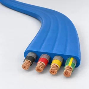
Flat Submersible Pump Cable 3 x 6 + 1 x 6 AWG
A related cable option for a different application or duty profile.
View productRequest a cable recommendation and quotation
Send the required services, cable length, mechanical duty, environment, termination and quantity. Our team will review the application before quoting.
- Include the product name or SKU plus the required cable length and quantity.
- Attach a specification, drawing or data sheet when available.