











Pendant Control Cable with Twin Steel Support Elements
300/500 V pendant control cable with two steel support elements for suspended control stations and movable consoles. Choose the 2ST PVC-insulated or R-type XLPE-insulated construction by circuit count, hanging length and termination geometry.
This pendant control cable family provides 300/500 V control connections with two steel support elements running along opposite sides of the cable. The 2ST construction uses extra-fine Class 6 copper conductors and PVC insulation; the R-type construction uses Class 5 copper conductors and XLPE insulation inside a twin-lobed PVC sheath.
Select the construction before selecting the circuit count. The support elements transfer suspended tensile forces to the designated clamps, while the insulated conductors carry the control circuits. This changes the suspension and termination design compared with an ordinary round control cable. Clamp dimensions must accommodate the support-member spacing or the complete twin-lobed profile.
The 2ST range covers 8G1.5, 12G1.5 and 20G1.5 configurations for movable panels and self-supporting shaft connections in high-rack equipment. R-type options cover 5 to 30 conductors of 1.5 mm² for overhead-crane pendant stations. Its documented suspended length is up to 50 m; use its own mechanical data when planning that route.
Specify the series, circuit schedule, suspended length, pendant mass and suspension arrangement with the enquiry. Check the flexible bending radius at the transition into the console and along any moving route. The configuration tables retain the different profiles and weights so the gland, clamp and available clearance can be matched to the selected cable.
Explore the port and festoon cable range for related configurations.
For self-supporting festoon and single-central-messenger crane control cables, compare these specifications: KYFLTFCY 300/500 V EMC Flat Festoon Cable with Suspension Element (for 300/500 V EMC-screened flat festoon installations with an integrated suspension strand); YSLTOE-J 300/500V Basket Control Cable (for round 300/500 V control drops supported by a central synthetic or steel strain-relief core). Check external support wire breaking load, core count, and pendant clamp compatibility before ordering.
Construction
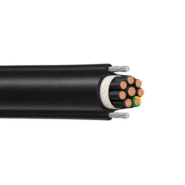
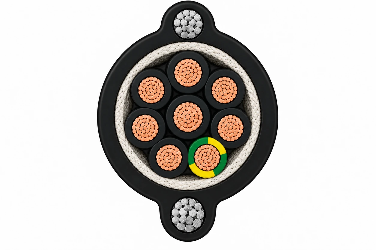
The representative 2ST 8G1.5 illustration shows eight insulated copper cores, including one green/yellow protective conductor, inside a black PVC cable body. Two separate steel support strands occupy opposite lateral extensions of the sheath. R-type uses the different XLPE-insulated, twin-lobed construction listed below.
| Component | Material and construction |
|---|---|
| 2ST conductor | Bare copper, extra-fine Class 6 stranding according to IEC 60228 / VDE 0295. |
| 2ST insulation and identification | Special PVC insulation; black cores with white numbers, plus a green/yellow protective conductor in G configurations. |
| 2ST assembly | Special textile wrapping around the laid-up insulated cores supports sliding between the core assembly and sheath. |
| 2ST support and sheath | Two opposing steel support elements integrated into a black special-PVC outer sheath. |
| R-type conductor and insulation | Plain copper, Class 5 according to IEC 60228, with flexible XLPE core insulation. |
| R-type profile | Twin-lobed PVC outer sheath with lateral steel suspension strands; use the overall width × height shown in its table. |
Applications
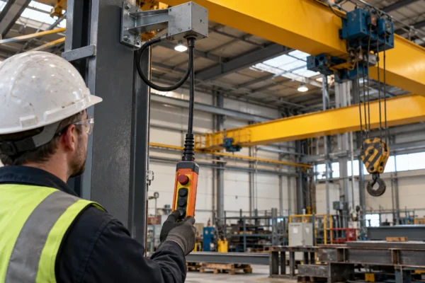
Use the twin steel supports with purpose-designed anchoring hardware to carry the suspended mechanical load at a pendant station, movable console or permitted shaft connection.

- 2ST: movable control panels, suspended control consoles and self-supporting shaft connections in high-rack systems; outdoor use within the stated operating conditions.
- R-type: remote-control push-button stations for overhead cranes, with a maximum suspended cable length of 50 m.
- Connect the steel support members to the designated strain-relief points so the electrical terminals do not carry the suspended mechanical load.
- Keep the series-specific bending radius at the pendant entry and moving transition. Include the complete cable profile when selecting clamps and glands.
- 2ST is not suitable for lift applications. Use a cable selected for the actual lift duty when that is the installation requirement.
When designing overhead hoist pendant stations and travelling crane festoon loops, review these resources: Crane Cable Manufacturer (for engineering support across crane festoon, reeling, basket, and pendant cable families); RONDOFLEX & PLANOFLEX Crane Festoon & Travelling Cable Series (0.6/1 kV) (for 0.6/1 kV round and flat rubber festoon cables on heavy gantry and bridge cranes). Confirm suspension height, oil and weather exposure, and numbered core layout.
Specifications
| Parameter | Value |
|---|---|
| Rated voltage U₀/U | 300/500 V |
| Cable duty | Suspended pendant and movable-console control connections |
| 2ST conductor / insulation | Class 6 bare copper / PVC |
| R-type conductor / insulation | Class 5 plain copper / XLPE |
| Outer sheath | Black PVC with two lateral steel support elements |
| 2ST configurations | 8G1.5, 12G1.5 and 20G1.5 |
| R-type configurations | 5–30 × 1.5 mm²; G configurations as separately listed |
| Model and configuration (mm²) | Cable body diameter (mm) | Support-wire centre distance (mm) | Copper index (kg/km) | Mass approx. (kg/km) |
|---|---|---|---|---|
| 2ST 8G1.5 | 13.6 | 19 | 115 | 430 |
| 2ST 12G1.5 | 15.5 | 21 | 172.8 | 510 |
| 2ST 20G1.5 | 20 | 25 | 288 | 720 |
| Model and configuration (mm²) | Overall width × height approx. (mm) | Mass approx. (kg/km) |
|---|---|---|
| R-type 5 × 1.5 | 20 × 9.5 | 210 |
| R-type 8 × 1.5 | 24 × 12.5 | 300 |
| R-type 12 × 1.5 | 24 × 12.5 | 350 |
| R-type 12G1.5 | 24 × 12.5 | 350 |
| R-type 16 × 1.5 | 25.5 × 14.5 | 440 |
| R-type 20 × 1.5 | 27 × 15.5 | 520 |
| R-type 20G1.5 | 27 × 15.5 | 520 |
| R-type 30 × 1.5 | 30 × 19 | 700 |
| Parameter | 2ST construction | R-type construction |
|---|---|---|
| AC test voltage | 4 kV | 2.5 kV |
| Flexible temperature condition | −15°C to +90°C | Mobile cable surface: −25°C to +60°C |
| Maximum conductor temperature in service | See the specified flexible operating condition | +90°C |
| Short-circuit conductor temperature | — | +250°C |
| Minimum bending radius, moving | 20 × cable body diameter | 10 × D |
| Steel support mechanical value | Tensile strength: 2100 N per support element | Maximum tensile load of the two supports together: 1000 N |
| Suspended route | Movable consoles and high-rack shaft connections | Maximum hanging length: 50 m |
G denotes a configuration containing a green/yellow protective conductor; the stated total core count includes that conductor. R-type rows marked × do not add a protective conductor to the listed count.
2ST cable-body diameter and support-wire centre distance are separate dimensions. R-type dimensions describe the complete width × height profile.
The 2ST support value is tensile strength per steel element. The R-type value is the specified maximum load for both supports together; use the correct series value in the suspension design.
D is the cable diameter used for the selected construction. Maintain the specified moving bend radius throughout the suspended transition.
Dimensions and masses are nominal selection data. Include suspension hardware, hanging length and pendant load with the required configuration.
Standards
| Standard or specification | Application |
|---|---|
| IEC 60228 / VDE 0295 | 2ST: Class 6 copper conductors; R-type: IEC 60228 Class 5 copper conductors. |
| VDE 0250 | Construction basis for the 2ST PVC control cable. |
| VDE 0293-334 | 2ST black insulated-core identification with white numbers. |
| IEC 60332-1-2 | 2ST flame-retardant cable reference. |
| AC dielectric testing | 2ST: 4 kV; R-type: 2.5 kV. |
| R-type mechanical tests | Alternating/reversed bending and torsional-resistance test references. |
Related cable options
Compare these cable options by service combination, movement, load, voltage and transmission requirement.

KYFLTFCY 300/500 V EMC Flat Festoon Cable with Suspension Element
A related cable option for a different application or duty profile.
View product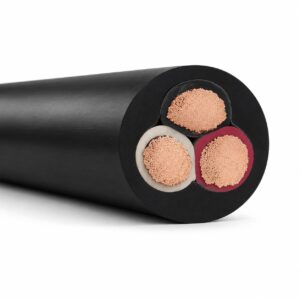
600V 2PNCT Flexible Rubber Cable (JIS C 3327)
A related cable option for a different application or duty profile.
View product
PNCT Reeling Cable 600 V–1 kV — Round, Flat and Reinforced Types
A related cable option for a different application or duty profile.
View productRequest a cable recommendation and quotation
Send the required services, cable length, mechanical duty, environment, termination and quantity. Our team will review the application before quoting.
- Include the product name or SKU plus the required cable length and quantity.
- Attach a specification, drawing or data sheet when available.