








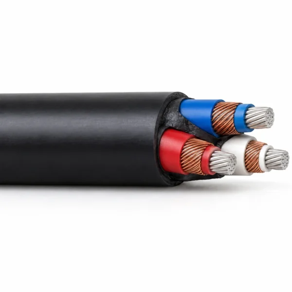
Type A and Type B 1.1/1.1 kV Mine Feeder Cable — AS/NZS 1972
AS/NZS 1972 Type A/B 1.1/1.1 kV cable for fixed mine power distribution: three stranded tinned-copper power cores, EPR insulation, copper-wire earth screens and heavy-duty PCP sheath. Type A offers three optional pilots; Type B is supplied without pilots.
Type A and Type B mine feeder cable distributes power within mines at 1.1/1.1 kV. The construction uses three stranded tinned-copper power conductors, EPR insulation, copper-wire screens that form the earth conductors, an elastomer centre filler and a heavy-duty PCP outer sheath. The listed power-conductor range is 16–240 mm², with construction references to AS/NZS 1972:2006.
Choose Type A when the specified circuit requires the optional three-pilot arrangement. Each pilot is insulated and covered with CPE and placed between the screened power cores. Type B provides the three screened power cores without pilots. State the required pilot arrangement with the power-conductor size: it determines the auxiliary wiring available at the termination and must agree with the mine’s control and protection circuit.
These configurations serve fixed mine distribution, including underground coal-mine installations selected to the project requirements. The copper-wire screens provide the specified earth-conductor sections; they are distinct from steel-wire armour or an additional insulated earth core. For machine connections specified as Type 1 screened machine cable or Type 2S and Type 2S.3 screened machine cables, use the corresponding construction and its own ratings. Match both the voltage and the specified construction when selecting the cable type.
Use the conductor and screen tables to identify the required build, then check the nominal outside diameter against the cable entry and route. TEBAOFLEX supplies Type A/B cable from a 50 m minimum order quantity, with a manufacturing lead time of 7–45 working days. Include the cable type, power size, pilot requirement, length and installation details in the enquiry.
Explore the mining and tunneling cable range for related configurations.
Construction
Type A and Type B share the screened three-power-core arrangement. The optional three CPE-covered pilots belong to Type A; Type B has no pilot cores. Copper-wire screens around the power cores provide the earth-conductor system. The main image illustrates Type B without pilots; Type A uses the pilot arrangement specified below.
| Component | Material and construction |
|---|---|
| Power conductors | Three Class 2 stranded, tinned annealed copper conductors; 16–240 mm² in the listed series. |
| Power insulation | EPR around each power conductor; thickness varies with conductor area. |
| Earth screens | Copper-wire screens around the individual insulated power cores, with the screen section listed for each size. |
| Centre filler | Elastomer centre filler supports the three-core arrangement. |
| Type A pilots | Three optional pilot conductors with composite CPE insulation and covering, laid in the interstitial spaces. Pilot stranding and covering thickness follow the size table. |
| Type B pilot arrangement | No pilot cores. |
| Outer sheath | Heavy-duty PCP enclosing the assembled core. |
Applications
Use the Type A/B designation, pilot requirement and earth-screen section together when specifying a fixed mine distribution circuit.
- Fixed 1.1/1.1 kV power distribution within mines.
- Underground coal-mine distribution circuits where this construction and the applicable mine requirements are specified.
- Type A feeder circuits that require three auxiliary pilot conductors in addition to the screened power cores.
- Type B feeder circuits that require the screened power cores without auxiliary pilots.
- Replacement of an existing Type A/B feeder after checking conductor section, screen section, pilot wiring, entry diameter and installation route.
For route and construction selection, see the mining and tunneling cable application guide.
Specifications
| Parameter | Value |
|---|---|
| Rated voltage U₀/U | 1.1/1.1 kV |
| Power-core count | Three |
| Listed conductor areas | 16, 25, 35, 50, 70, 95, 120, 150, 185 and 240 mm² |
| Conductor material | Stranded tinned annealed copper |
| Insulation / sheath | EPR / heavy-duty PCP |
| Earth-conductor arrangement | Individual copper-wire power-core screens |
| Type A pilot option | Three CPE-insulated and covered pilot cores |
| Type B pilot arrangement | No pilot cores |
| Installation duty | Fixed mine distribution |
| Minimum order quantity | 50 m |
| Manufacturing lead time | 7–45 working days |
| Model and configuration | Power-core insulation | Earth-conductor arrangement | Pilot arrangement | Outer sheath |
|---|---|---|---|---|
| Type A 3 power cores + 3 optional pilots | EPR | Copper-wire screen around each power core | Three CPE-insulated and covered pilot cores when specified | Heavy-duty PCP |
| Type B 3 power cores, without pilots | EPR | Copper-wire screen around each power core | No pilot cores | Heavy-duty PCP |
| Model and power configuration | Power stranding (no./mm) | EPR insulation (mm) | Earth screen per core (mm²) | Each optional pilot (no./mm) | Pilot covering (mm) |
|---|---|---|---|---|---|
| Type A 3 × 16 mm² + 3 optional pilots | 7/1.70 | 1.4 | 6.0 | 24/0.20 | 1.6 |
| Type A 3 × 25 mm² + 3 optional pilots | 19/1.35 | 1.4 | 7.2 | 32/0.20 | 1.8 |
| Type A 3 × 35 mm² + 3 optional pilots | 19/1.53 | 1.5 | 7.9 | 30/0.25 | 1.8 |
| Type A 3 × 50 mm² + 3 optional pilots | 19/1.78 | 1.7 | 9.0 | 50/0.25 | 2.0 |
| Type A 3 × 70 mm² + 3 optional pilots | 19/2.14 | 1.8 | 13.2 | 80/0.25 | 2.0 |
| Type A 3 × 95 mm² + 3 optional pilots | 19/2.52 | 2.0 | 15.1 | 80/0.25 | 2.0 |
| Type A 3 × 120 mm² + 3 optional pilots | 37/2.03 | 2.2 | 22.9 | 80/0.25 | 2.0 |
| Type A 3 × 150 mm² + 3 optional pilots | 37/2.25 | 2.3 | 24.7 | 80/0.25 | 2.0 |
| Type A 3 × 185 mm² + 3 optional pilots | 37/2.52 | 2.5 | 27.5 | 80/0.25 | 2.0 |
| Type A 3 × 240 mm² + 3 optional pilots | 61/2.25 | 2.7 | 64.4 | 80/0.25 | 2.0 |
| Model and power configuration | Power stranding (no./mm) | EPR insulation (mm) | Copper screen wires (no./mm) | Earth screen per core (mm²) |
|---|---|---|---|---|
| Type B 3 × 16 mm², no pilots | 7/1.70 | 1.4 | 48/0.40 | 6.0 |
| Type B 3 × 25 mm², no pilots | 19/1.35 | 1.4 | 57/0.40 | 7.2 |
| Type B 3 × 35 mm², no pilots | 19/1.53 | 1.5 | 63/0.40 | 7.9 |
| Type B 3 × 50 mm², no pilots | 19/1.78 | 1.7 | 72/0.40 | 9.0 |
| Type B 3 × 70 mm², no pilots | 19/2.14 | 1.8 | 67/0.50 | 13.2 |
| Type B 3 × 95 mm², no pilots | 19/2.52 | 2.0 | 77/0.50 | 15.1 |
| Type B 3 × 120 mm², no pilots | 37/2.03 | 2.2 | 65/0.67 | 22.9 |
| Type B 3 × 150 mm², no pilots | 37/2.25 | 2.3 | 70/0.67 | 24.7 |
| Type B 3 × 185 mm², no pilots | 37/2.52 | 2.5 | 78/0.67 | 27.5 |
| Type B 3 × 240 mm², no pilots | 61/2.25 | 2.7 | 45/1.35 | 64.4 |
| Model and power configuration | PCP sheath (mm) | Nominal OD (mm) | Nominal mass (kg/100 m) |
|---|---|---|---|
| Type A/B 3 × 16 mm² | 2.5 | 24.6 | 120 |
| Type A/B 3 × 25 mm² | 2.5 | 28.0 | 170 |
| Type A/B 3 × 35 mm² | 2.5 | 30.4 | 205 |
| Type A/B 3 × 50 mm² | 3.0 | 34.9 | 270 |
| Type A/B 3 × 70 mm² | 3.3 | 40.2 | 370 |
| Type A/B 3 × 95 mm² | 3.8 | 46.1 | 490 |
| Type A/B 3 × 120 mm² | 3.8 | 51.1 | 615 |
| Type A/B 3 × 150 mm² | 4.4 | 56.0 | 740 |
| Type A/B 3 × 185 mm² | 5.1 | 62.3 | 915 |
| Type A/B 3 × 240 mm² | 5.7 | 72.9 | 1290 |
The pilot stranding and covering columns apply only to the optional three-pilot Type A build. They are not additional earth-conductor specifications.
The dimensions and weight are a joint Type A/B nominal family series. Identify Type A with the selected pilot option or Type B without pilots on the quotation and termination drawing; do not infer a different Type B weight by subtracting pilot copper.
Screen areas refer to the copper-wire earth screen associated with each power core. Match the specified earth system and protection requirements before selecting the cable.
Stranding is shown as number of wires / wire diameter in millimetres. It must not be read as conductor area.
Mass is expressed in kg per 100 m. Dimensions and masses are nominal reference values; confirm the selected build and cable-entry dimensions on the quotation.
Determine the circuit current rating from the selected conductor and the actual installation, ambient and grouping conditions.
AS/NZS 1972 Type A/B and AS/NZS 1972 machine-cable designations such as Type 1 or Type 2S require their own construction and voltage data; they are not interchangeable names.
Standards
| Standard or specification | Application |
|---|---|
| AS/NZS 1972:2006 | Type A/B mine distribution cable construction reference for this 1.1/1.1 kV series. |
| AS/NZS 1125 | Copper conductor construction reference. |
| AS/NZS 3808 | Insulation and sheathing compound reference. |
Official standards and approval references
- Standards New Zealand — AS/NZS 1972:2006 official review record — Official identification of the 2006 standard in the 2026 review programme; a review date is not a new edition or a product certificate.
Certifications and document support
Review our company certificates and document scopes when identifying the documentation required for the quoted construction.
State the required standard edition, Type A or Type B, conductor size, pilot arrangement and any project-specific acceptance documentation. Match the documents to the fixed-distribution construction and the ordered pilot configuration. Standard references and company management-system records serve different purposes from product-specific approval or test records.
Related cable options
Compare these cable options by service combination, movement, load, voltage and transmission requirement.
Mine Feeder Type 1 Screened Machine Cable 1.1/1.1 kV
A related cable option for a different application or duty profile.
View product
Mine Feeder Type 2S and Type 2S.3 Screened Machine Cable 1.1/1.1–3.3/3.3 kV
A related cable option for a different application or duty profile.
View product
Mine Borehole & Shaft Self-Supporting Armoured Drop Cable (0.6/1–15 kV)
A related cable option for a different application or duty profile.
View productRequest a cable recommendation and quotation
Send the required services, cable length, mechanical duty, environment, termination and quantity. Our team will review the application before quoting.
- Include the product name or SKU plus the required cable length and quantity.
- Attach a specification, drawing or data sheet when available.