


Compact Hybrid Fiber Optic Power Cable
Compact Hybrid Fiber Optic Power Cable brings 2 selectable construction options together for compact ROV, sensor, camera and underwater-robotics designers. Compare the complete signal, electrical and mechanical requirement before choosing a configuration.
- Selection focus: fit optical data and electrical power into compact ROV, sensor and underwater-robotics interfaces
- Available configurations: 2
- Mechanical inputs: cable length, working load, drum, sheave, routing and deployment cycle
- Quotation inputs: services, environment, termination, quantity and required inspection documents
Compact Hybrid Fiber Optic Power Cable selection overview
The Compact Hybrid Fiber Optic Power Cable gives compact ROV, sensor, camera and underwater-robotics designers one clear route for comparing 2 available constructions. It is designed to fit optical data and electrical power into compact ROV, sensor and underwater-robotics interfaces. Keeping the options in one product group makes it easier to compare signal architecture, conductor or fibre content, armour, diameter, mechanical load and bend geometry without switching between separate product pages.
Selection starts with the equipment interface: define voltage and current, signal type and frequency, coaxial impedance and allowable attenuation, or fibre type, count and wavelength as applicable. Then define whether the cable will be static, suspended, reeled, towed or repeatedly deployed. Cable length, working load, breaking-load criterion, drum and sheave dimensions, temperature, water environment, abrasion, buoyancy and the connector or moulded termination must be reviewed as one system.
- Compare: construction, transmission values, outside diameter, load and bend data shown for each option.
- Confirm: the complete service combination and the operating values that apply at the required cable length.
- Specify: inspection stages, test methods, acceptance values, marking and documentation in the quotation.
Use the related subsea and marine cable selection page for the wider application route, or send your equipment and deployment requirements for an engineering review.
Compact Hybrid Fiber Optic Power Cable construction options
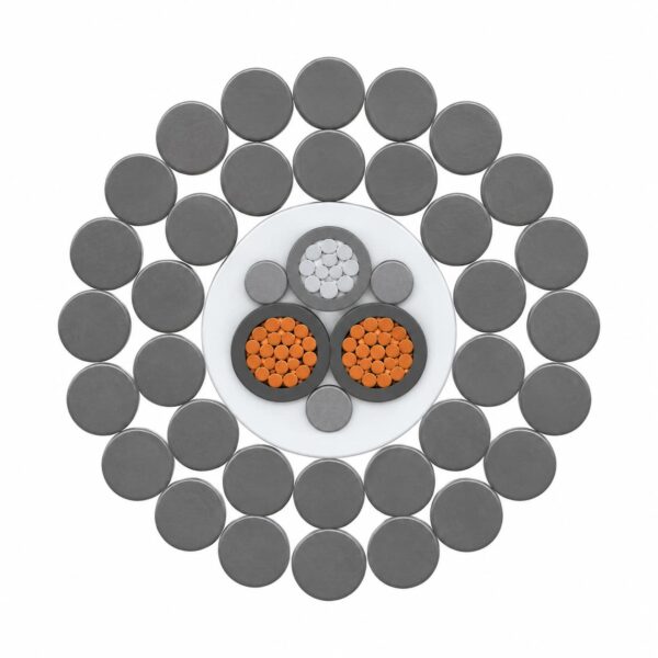
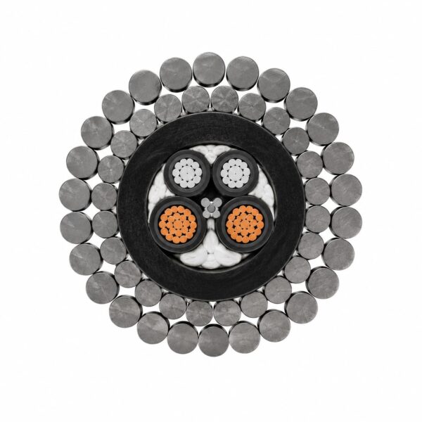
Compare the complete layer sequence for each option. Conductor or fibre elements, insulation, screening, fillers, bedding, strength members, armour and outer sheath are selected together to suit the transmission and deployment duty.| Configuration | Construction |
|---|---|
| Two fibers plus three 1.50 mm² power cores | 2 × 9/125 single-mode fibers + 3 × 1.50 mm²; PUR; galvanized steel armour |
| Two FIMT fibers plus two 17 AWG power cores | 2 × 9/125 fibers in stainless-steel tube + 2 × 17 AWG; ETFE; HDPE; galvanized steel armour |
Construction selection
Armour material and lay, sheath material, waterblocking, screening and fibre protection are matched to corrosion exposure, abrasion, repeated bending, handling load and termination design. The armour anchoring and connector or moulded transition are reviewed with the cable because they control how load and water sealing are transferred into the equipment.Applications for Compact Hybrid Fiber Optic Power Cable
This product group supports compact ROV, sensor, camera and underwater-robotics designers where transmission performance and mechanical deployment duty must be selected together.- Compact ROVs, sensors, cameras and underwater robotics requiring two optical fibers plus electrical power.
- Space-constrained vehicles and connectors where cable diameter and bend geometry are controlling inputs.
- Use a high-load deepwater hybrid route when the mechanical or service requirement exceeds the compact configuration envelope.
Information needed for selection
Provide the equipment, cable length, service voltages or signals, load criterion, winch and sheave dimensions, deployment method, water environment, temperature, buoyancy target, connector or moulding interface and required inspection documents.Compact Hybrid Fiber Optic Power Cable specifications
Use the stated values to compare complete configuration options. Empty properties are omitted instead of being estimated, and each numerical value stays with the construction under which it is listed.Two fibers plus three 1.50 mm² power cores
| Construction | 2 × 9/125 single-mode fibers + 3 × 1.50 mm²; PUR; galvanized steel armour |
|---|---|
| Voltage / test value | 600 V |
| Outside diameter | 15.20 mm |
| Breaking load | 10000 kg |
| Working load | 3000 kg |
| Static bend radius | 76 mm |
| Dynamic bend radius | 152 mm |
| Temperature | -30 to +80°C |
Two FIMT fibers plus two 17 AWG power cores
| Construction | 2 × 9/125 fibers in stainless-steel tube + 2 × 17 AWG; ETFE; HDPE; galvanized steel armour |
|---|---|
| Voltage / test value | 1000 V |
| Optical attenuation | < 0.45 dB/km @ 1310 nm; < 0.30 dB/km @ 1550 nm |
| Outside diameter | 10.60 mm |
| Breaking load | 89 kN |
| Working load | 22.25 kN |
| Static bend radius | 100 mm |
| Dynamic bend radius | 200 mm |
| Temperature | -40 to +80°C |
Using the values
Breaking load is not the normal operating load. Bend values must match drums, sheaves, guides and connector exits. A voltage entry that includes a duration is a dielectric test value rather than a continuous rated voltage. Confirm the applicable operating and acceptance values in the quotation.Standards and test references
The applicable references are selected for the confirmed cable construction and project duty. They provide a framework for engineering and inspection rather than a one-size-fits-all cable designation.- IEC 60794-1-2:2021: General guidance for optical-fibre cable tests, including cables that combine optical fibres and electrical conductors.
- IEC 60794-1-21 / IEC 60794-1-22: Mechanical and environmental test-method families for optical and hybrid optical cables.
- IEC 60793-2-50 and ITU-T G.652: Single-mode optical-fibre characteristics when G.652-type fibre is specified.
- Project test plan: Defines optical wavelengths, attenuation method, tensile load, bending, temperature, water exposure, electrical checks and termination acceptance.
Related cable options
Compare these cable options by service combination, movement, load, voltage and transmission requirement.
Subsea Armoured Fiber Optic Cable
A related cable option for a different application or duty profile.
View product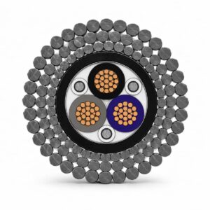
Deepwater High-Load Hybrid Fiber Optic Cable
A related cable option for a different application or duty profile.
View productRequest a cable recommendation and quotation
Send the required services, cable length, mechanical duty, environment, termination and quantity. Our team will review the application before quoting.
- Include the product name or SKU plus the required cable length and quantity.
- Attach a specification, drawing or data sheet when available.