










MGM 110 Armoured Mine Telephone & Signal Cable, 110 V
MGM 110 110 V fixed mine telephone and signal cable with 1.5 mm² tinned copper conductors, PVC insulation and single- or double-layer galvanized steel armour. Choose 2–91 signal cores or 1–61 telephone pairs.
MGM 110 is a 110 V armoured communication cable for fixed telephone and signal circuits in underground mines and surface installations. The range combines 1.5 mm² tinned copper conductors with PVC insulation, PVC bedding, galvanized steel wire armour and a special PVC outer sheath. Single-layer and double-layer armour versions support different mechanical protection requirements along the cable route.
Choose the core arrangement to match the circuit. Signal constructions contain 2 to 91 individual insulated cores. Telephone constructions contain 1 to 61 twisted pairs, with two 1.5 mm² conductors in each pair. Keeping these arrangements distinct makes it easier to specify terminals, identify circuits and select the correct cable diameter. A four-core signal cable and a two-pair telephone cable have the same conductor count, but their internal lay-up differs.
The armour surrounds the PVC-bedded core assembly to protect fixed runs against mechanical damage. For cable supports, glands and entry openings, use the diameter and minimum bend radius of the selected armour version. The double-layer construction generally requires more space and carries a greater installed weight than the corresponding single-layer cable.
The specification tables below keep all four combinations separate: signal or telephone lay-up with single-layer or double-layer armour. Include the required core or pair count, armour build and installation conditions in your enquiry so the cable and termination details can be matched to the project. Explore the mining and tunneling cable range for related mine circuits.
Use the fixed armoured mining cable guide to distinguish fixed routes from trailing and reeling duty.
Construction
The representative illustration shows a single-layer armoured MGM 110 4 × 1.5 mm² signal cable. Telephone variants use twisted pairs; double-layer variants add a second steel armour layer.

| Component | Material and arrangement |
|---|---|
| Conductor | Stranded tinned copper, IEC 60228 Class 2; the listed dimensional constructions use 7/0.5 mm stranding and 1.5 mm² nominal conductor area. |
| Core insulation | PVC; nominal radial insulation thickness 0.5 mm. Listed insulated core diameter: 2.36–2.64 mm. |
| Signal lay-up | Individual insulated cores laid up in contact with one another. |
| Telephone lay-up | Insulated conductors laid up in twisted pairs. |
| Bedding / inner sheath | PVC-based bedding compound. Thickness varies with configuration. |
| Single-layer armour | One layer of helically applied galvanized steel wires. |
| Double-layer armour | Two layers of helically applied galvanized steel wires. |
| Optional separator | Galvanized steel tape, when specified. |
| Outer sheath | Special PVC compound; thickness varies with configuration. |
Applications
MGM 110 serves fixed mine telephone and signalling networks in underground workings and surface plant. Use the telephone construction where the circuit calls for paired conductors; select the signal construction for a specified multi-core signal arrangement.

- Fixed telephone connections along mine roadways and between mine service points.
- Fixed signalling circuits in galleries, tunnels and surface mining facilities.
- Mechanically protected communication routes using cable supports, trays or other project-approved mounting arrangements.
Select the armour build with the installation route, mechanical protection and termination arrangement. The circuit voltage must remain within the 110 V rating. Follow the mine electrical design and applicable installation rules for hazardous areas.
Where the cable schedule specifies PE-insulated mine communication cable, review the MHYV mining communication cable family for model-specific conductor groups and protective layers.
For fixed power distribution, compare the fixed mining power cable range. For a moving or suspended hoist circuit, use the underground mine hoist cable selection.
Specifications
| Parameter | Value |
|---|---|
| Rated voltage | 110 V |
| Test voltage | 1 kV |
| Nominal conductor area | 1.5 mm² |
| Conductor construction in the listed size tables | 7/0.5 mm stranded tinned copper; nominal conductor diameter 1.50 mm |
| Core insulation thickness | 0.5 mm |
| Insulated core diameter | 2.36 mm minimum; 2.64 mm maximum |
| Ambient operating temperature | −20°C to +60°C |
| Maximum operating temperature | +70°C |
| Signal configurations | 2, 4, 7, 10, 12, 14, 19, 37, 61 or 91 cores × 1.5 mm² |
| Telephone configurations | 1, 2, 4, 7, 10, 12, 19, 27, 30, 37, 48 or 61 pairs × 2 × 1.5 mm² |
| Installation | Fixed |
| Armour choices | Single layer or double layer of galvanized steel wires |
Single-layer armoured signal cable
Signal configuration is expressed as number of individual cores × conductor area.
| Model and configuration | Inner sheath (mm) | Armour wire Ø (mm) | Outer sheath (mm) | Overall Ø min.–max. (mm) | Min. bend radius (mm) | Approx. weight (kg/km) | Copper weight (kg/km) |
|---|---|---|---|---|---|---|---|
| MGM 110 2 × 1.5 mm² | 1 | 0.9 | 1.4 | 11.6–13 | 104 | 320 | 30 |
| MGM 110 4 × 1.5 mm² | 1 | 0.9 | 1.5 | 12.8–14.4 | 116 | 395 | 60 |
| MGM 110 7 × 1.5 mm² | 1 | 0.9 | 1.5 | 14.2–15.8 | 127 | 500 | 105 |
| MGM 110 10 × 1.5 mm² | 1 | 1.25 | 1.6 | 17.7–19.3 | 155 | 780 | 150 |
| MGM 110 12 × 1.5 mm² | 1 | 1.25 | 1.6 | 18.1–19.7 | 158 | 850 | 180 |
| MGM 110 14 × 1.5 mm² | 1 | 1.25 | 1.6 | 18.6–20.6 | 165 | 920 | 210 |
| MGM 110 19 × 1.5 mm² | 1 | 1.25 | 1.7 | 20.2–22.2 | 178 | 1100 | 280 |
| MGM 110 37 × 1.5 mm² | 1.2 | 1.6 | 1.8 | 26.5–28.9 | 232 | 1900 | 540 |
| MGM 110 61 × 1.5 mm² | 1.2 | 1.6 | 2 | 32.1–34.5 | 276 | 2740 | 880 |
| MGM 110 91 × 1.5 mm² | 1.4 | 2 | 2.2 | 38.5–41.3 | 331 | 4050 | 1315 |
Single-layer armoured telephone cable
Telephone configuration is expressed as pairs × 2 × conductor area.
| Model and configuration | Inner sheath (mm) | Armour wire Ø (mm) | Outer sheath (mm) | Overall Ø min.–max. (mm) | Min. bend radius (mm) | Approx. weight (kg/km) | Copper weight (kg/km) |
|---|---|---|---|---|---|---|---|
| MGM 110 1 × 2 × 1.5 mm² | 1 | 0.9 | 1.4 | 11.6–13 | 104 | 320 | 30 |
| MGM 110 2 × 2 × 1.5 mm² | 1 | 0.9 | 1.5 | 12.8–14.4 | 116 | 395 | 60 |
| MGM 110 4 × 2 × 1.5 mm² | 1 | 1.25 | 1.5 | 16.7–19.3 | 155 | 690 | 120 |
| MGM 110 7 × 2 × 1.5 mm² | 1 | 1.25 | 1.6 | 20.5–22.5 | 180 | 900 | 210 |
| MGM 110 10 × 2 × 1.5 mm² | 1.2 | 1.6 | 1.7 | 26–28 | 224 | 1350 | 290 |
| MGM 110 12 × 2 × 1.5 mm² | 1.2 | 1.6 | 1.7 | 26.5–28.9 | 232 | 1460 | 350 |
| MGM 110 19 × 2 × 1.5 mm² | 1.2 | 1.6 | 1.8 | 30.5–32.9 | 264 | 2000 | 550 |
| MGM 110 27 × 2 × 1.5 mm² | 1.4 | 2 | 2 | 36.9–39.5 | 316 | 2800 | 780 |
| MGM 110 30 × 2 × 1.5 mm² | 1.4 | 2 | 2 | 37–39.6 | 317 | 3000 | 870 |
| MGM 110 37 × 2 × 1.5 mm² | 1.4 | 2 | 2.1 | 40.8–43.6 | 349 | 3450 | 1070 |
| MGM 110 48 × 2 × 1.5 mm² | 1.4 | 2 | 2.3 | 46.1–48.9 | 392 | 4160 | 1390 |
| MGM 110 61 × 2 × 1.5 mm² | 1.6 | 2.5 | 2.4 | 51.3–54.5 | 436 | 5500 | 1760 |
Double-layer armoured signal cable
Signal configuration is expressed as number of individual cores × conductor area.
| Model and configuration | Inner sheath (mm) | Armour wire Ø (mm) | Outer sheath (mm) | Overall Ø min.–max. (mm) | Min. bend radius (mm) | Approx. weight (kg/km) | Copper weight (kg/km) |
|---|---|---|---|---|---|---|---|
| MGM 110 2 × 1.5 mm² | 1 | 0.9 | 1.5 | 15.9–17.3 | 156 | 570 | 30 |
| MGM 110 4 × 1.5 mm² | 1 | 0.9 | 1.6 | 17–18.6 | 168 | 680 | 60 |
| MGM 110 7 × 1.5 mm² | 1 | 0.9 | 1.6 | 17.5–19.1 | 172 | 820 | 105 |
| MGM 110 10 × 1.5 mm² | 1 | 1.25 | 1.7 | 22.8–24.4 | 220 | 1280 | 150 |
| MGM 110 12 × 1.5 mm² | 1 | 1.25 | 1.7 | 23.2–24.8 | 224 | 1350 | 180 |
| MGM 110 14 × 1.5 mm² | 1 | 1.25 | 1.7 | 23.8–25.8 | 233 | 1450 | 210 |
| MGM 110 19 × 1.5 mm² | 1 | 1.25 | 1.8 | 25.3–27.3 | 246 | 1650 | 280 |
| MGM 110 37 × 1.5 mm² | 1.2 | 1.6 | 1.9 | 32.5–34.9 | 315 | 2850 | 540 |
| MGM 110 61 × 1.5 mm² | 1.2 | 1.6 | 2.1 | 37.7–40.1 | 361 | 3000 | 880 |
| MGM 110 91 × 1.5 mm² | 1.4 | 2 | 2.3 | 45.1–47.9 | 432 | 5600 | 1315 |
Double-layer armoured telephone cable
Telephone configuration is expressed as pairs × 2 × conductor area.
| Model and configuration | Inner sheath (mm) | Armour wire Ø (mm) | Outer sheath (mm) | Overall Ø min.–max. (mm) | Min. bend radius (mm) | Approx. weight (kg/km) | Copper weight (kg/km) |
|---|---|---|---|---|---|---|---|
| MGM 110 1 × 2 × 1.5 mm² | 1 | 0.9 | 1.5 | 15.9–17.3 | 156 | 570 | 30 |
| MGM 110 2 × 2 × 1.5 mm² | 1 | 0.9 | 1.6 | 17–18.6 | 168 | 680 | 60 |
| MGM 110 4 × 2 × 1.5 mm² | 1 | 1.25 | 1.6 | 22.7–24.4 | 220 | 1250 | 120 |
| MGM 110 7 × 2 × 1.5 mm² | 1 | 1.25 | 1.7 | 25.3–27.3 | 246 | 1580 | 210 |
| MGM 110 10 × 2 × 1.5 mm² | 1.2 | 1.6 | 1.9 | 32–34 | 306 | 2350 | 290 |
| MGM 110 12 × 2 × 1.5 mm² | 1.2 | 1.6 | 1.9 | 32.4–34.8 | 314 | 2550 | 350 |
| MGM 110 19 × 2 × 1.5 mm² | 1.2 | 1.6 | 2 | 36.2–38.6 | 348 | 3280 | 550 |
| MGM 110 27 × 2 × 1.5 mm² | 1.4 | 2 | 2.2 | 43.6–46.2 | 416 | 4680 | 780 |
| MGM 110 30 × 2 × 1.5 mm² | 1.4 | 2 | 2.2 | 44.7–47.3 | 426 | 4950 | 870 |
| MGM 110 37 × 2 × 1.5 mm² | 1.4 | 2 | 2.3 | 47.3–50.1 | 451 | 5620 | 1070 |
| MGM 110 48 × 2 × 1.5 mm² | 1.4 | 2 | 2.4 | 52.5–55.3 | 498 | 6590 | 1390 |
| MGM 110 61 × 2 × 1.5 mm² | 1.6 | 2.5 | 2.6 | 58.8–62 | 558 | 8800 | 1760 |
Dimensions and weights apply to the specified configuration and armour build. Use the selected row for cable entry, support and bend planning.
Standards
| Reference | Scope |
|---|---|
| MGM 110/1984 | Turkish specification for PVC-insulated, steel-armoured mine telephone and signal cables. |
| IEC 60228 | Conductor construction and conductor classification. |
The Turkish Hard Coal Enterprises telephone-cable specification provides procurement context for fixed mine telephone circuits using the MGM 110/1984 construction basis.
Related cable options
Compare these cable options by service combination, movement, load, voltage and transmission requirement.
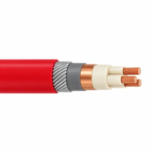
Fixed Mining Power Cable — PVC / HEPR, SWA / STA Options
A related cable option for a different application or duty profile.
View product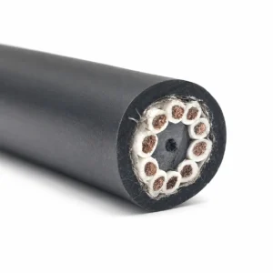
NTMTWOEU 600/1000 V Underground Mine Hoist Cable
A related cable option for a different application or duty profile.
View product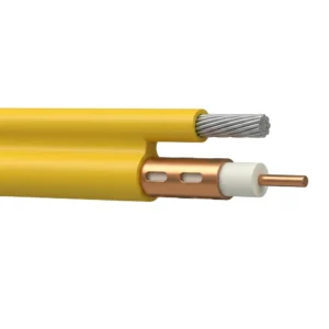
Underground Mine Leaky Feeder Coaxial Communication Cable (50 / 75 Ohm)
A related cable option for a different application or duty profile.
View productRequest a cable recommendation and quotation
Send the required services, cable length, mechanical duty, environment, termination and quantity. Our team will review the application before quoting.
- Include the product name or SKU plus the required cable length and quantity.
- Attach a specification, drawing or data sheet when available.