










XAT/EVA FO 35 kV Armoured Mining Cable
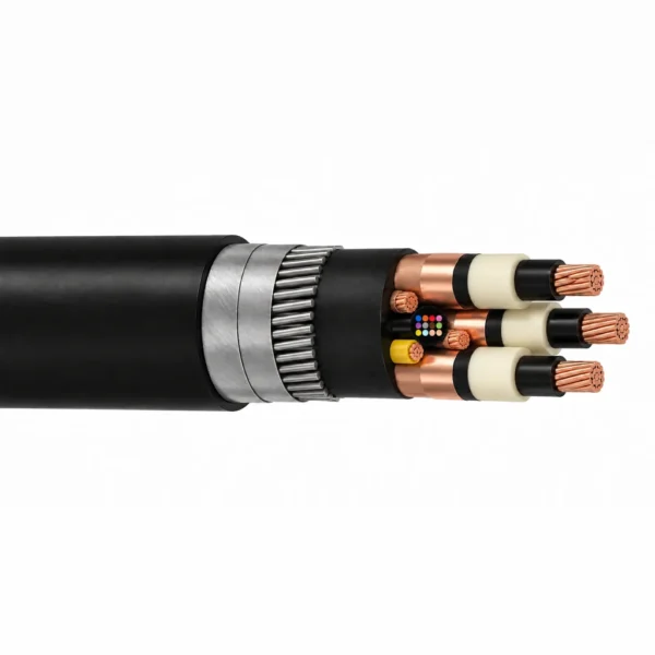
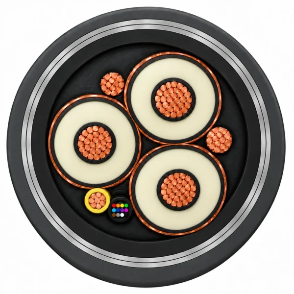
XAT/EVA FO 35 kV armoured cable combines power, grounding, ground-check and 12 single-mode optical fibres for fixed feeder connections.
- Power conductors: 3 × 500 kcmil copper.
- Grounding and ground-check: 2 × 4/0 AWG + 1 × 6 AWG.
- Insulation and screens: XLPE-TR with semiconductive layers and individual copper tapes.
- Armour options: AA+FA steel wires and two steel tapes; FA two steel tapes.
- Coverings: low-smoke, halogen-free inner covering and EVA outer sheath.
Send the armour option, route, length and termination requirements for a quotation.
XAT/EVA FO cable is a 35 kV armoured power-and-fibre assembly for fixed feeder and substation connections. The configuration brings three copper phase conductors together with two grounding conductors, a separate ground-check conductor and 12 single-mode optical fibres. FA and AA+FA are alternative armour constructions within this electrical arrangement.
Each power core combines XLPE-TR insulation with extruded semiconductive layers and an individual copper-tape screen. Low-smoke, halogen-free filling, inner covering and an EVA outer sheath complete the assembled cable around its power, grounding and optical elements.
Select the armour before checking the route dimensions. AA+FA adds steel wires beneath two steel tapes; FA uses two steel tapes. The resulting differences in diameter, weight and bending radius affect support space, handling arrangements and the path into the equipment. The Specifications tables keep the final-position and installation bending limits separate for each construction.
For a quotation, identify the armour option and required length, and provide the feeder route, support arrangement and power, grounding, ground-check and optical termination requirements. Include the project optical-fibre specification and installation pulling requirements so these can be addressed with the cable selection.
Browse the mining and tunneling cable range for related duties. For route selection, consult the fixed armoured mining cable guide.
Construction
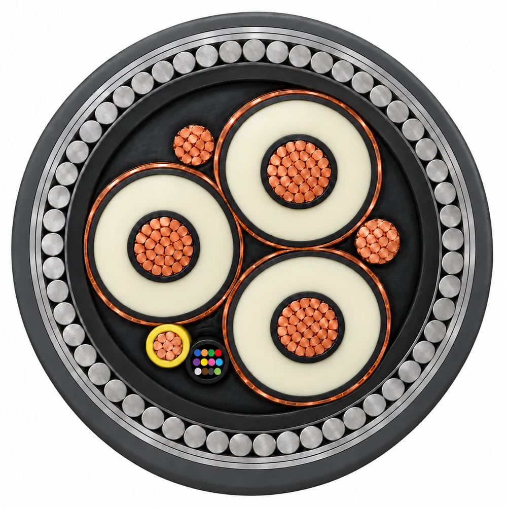
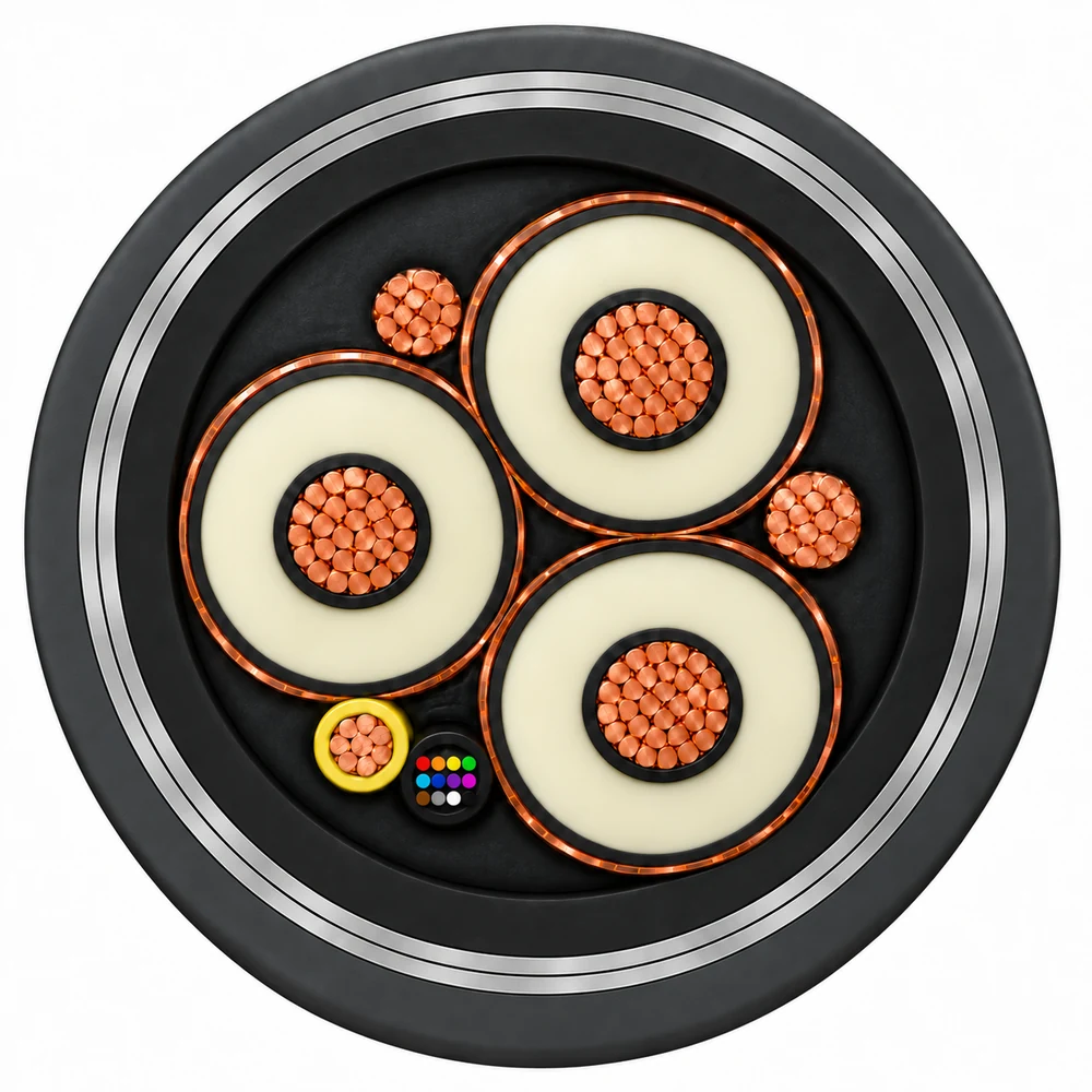
The two XAT/EVA FO constructions share three screened power cores, two bare grounding conductors, a separate yellow PE-insulated ground-check conductor and one optical unit containing 12 single-mode fibres. Their armour layers differ.
| Element | Material and arrangement |
|---|---|
| Phase conductors | Three compact round stranded copper conductors, 500 kcmil each; conductor construction references ASTM B496 or ASTM B835. |
| Conductor screens | Extruded thermosetting semiconductive layers over the phase conductors. |
| Power-core insulation | Tree-retardant cross-linked polyethylene (XLPE-TR); minimum insulation thickness 10.2 mm. |
| Insulation screens | Extruded thermosetting semiconductive layers over the insulation. |
| Metallic screens | Overlapped annealed copper tape over each screened phase core. |
| Grounding conductors | Two bare round stranded copper conductors, Class B, 4/0 AWG each. |
| Ground-check conductor | One extra-flexible bare copper conductor, 6 AWG, insulated with yellow PE. |
| Optical unit | 12 single-mode optical fibres within the cable assembly. |
| Filling and inner covering | Low-smoke, zero-halogen (LS0H) compounds with flame-retardant properties. |
| Outer sheath | EVA / LS0H compound with flame-retardant properties. |
| Construction | Armour over the inner covering |
|---|---|
| XAT/EVA FO AA+FA | Steel wires followed by two steel tapes. |
| XAT/EVA FO FA | Two steel tapes. |
Select and identify the armour option in the order and end-connection drawing. Keep the phase screens, grounding conductors, ground-check circuit and optical fibres identifiable when planning termination.
Applications
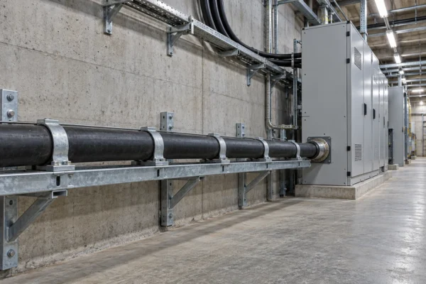
XAT/EVA FO cable is intended for fixed power transmission and distribution connections to and from substations, including outdoor and underground industrial routes in dry or damp environments.

- Fixed mine feeder routes requiring medium-voltage power and integrated optical fibres.
- Supported cable routes between distribution equipment and substation connections.
- Installations where low-smoke, halogen-free coverings form part of the project specification.
Plan supports and handling around the selected construction's diameter, weight and bending limits. Use the installation radius while placing the cable and the final-position radius for its installed route. Define any pulling, elevation and termination requirements in the project drawing.
For equipment that drags or repeatedly reels its supply cable, select a cable construction intended for that movement duty.
Specifications
| Parameter | Value and condition |
|---|---|
| Model | XAT/EVA FO |
| Voltage designation | 35 kV |
| Installation duty | Fixed feeder and substation connections |
| Power conductor configuration | 3 × 500 kcmil copper |
| Grounding conductor configuration | 2 × 4/0 AWG |
| Ground-check conductor configuration | 1 × 6 AWG, yellow PE insulation |
| Optical fibres | 12 single-mode fibres |
| Approximate phase conductor diameter | 18.7 mm |
| Minimum insulation thickness | 10.2 mm |
| Maximum DC conductor resistance at 20°C | 0.0708 Ω/km |
| Service temperature | 90°C |
| Emergency temperature | 130°C |
| Short-circuit temperature | 250°C |
| Configuration | Nominal overall diameter (mm) | Approximate weight (kg/m) | Minimum bending radius, final position (mm) | Minimum bending radius, during installation (mm) |
|---|---|---|---|---|
| XAT/EVA FO 3 × 500 kcmil + 2 × 4/0 AWG + 1 × 6 AWG, 35 kV, 12FO, AA+FA | 119 | 30.1 | 1428 | 2142 |
| Configuration | Nominal overall diameter (mm) | Approximate weight (kg/m) | Minimum bending radius, final position (mm) | Minimum bending radius, during installation (mm) |
|---|---|---|---|---|
| XAT/EVA FO 3 × 500 kcmil + 2 × 4/0 AWG + 1 × 6 AWG, 35 kV, 12FO, FA | 108 | 20.1 | 1296 | 1944 |
Dimensions and weights are nominal or approximate as indicated. Apply the bending limits for the selected armour; the final-position and installation values describe different stages of the route.
For selection, state the electrical system, cable length, installation method, optical-fibre requirements and the termination arrangement for each conductor and optical element.
Standards
| Reference | Application to the specified construction |
|---|---|
| ICEA S-93-639 | Design, construction and test reference for the specified shielded medium-voltage cable. |
| ASTM B496 or ASTM B835 | Construction references for the compact round stranded copper phase conductors. |
| LS0H / EVA coverings | Low-smoke, halogen-free filling, inner covering and outer sheath with flame-retardant properties. |
For the official shielded power cable standard listing, consult the ICEA standards directory.
Related cable options
Compare these cable options by service combination, movement, load, voltage and transmission requirement.
Type MP-GC 15kV Mine Power Feeder Cable
A related cable option for a different application or duty profile.
View product
Fixed Mining Power Cable — PVC / HEPR, SWA / STA Options
A related cable option for a different application or duty profile.
View productRequest a cable recommendation and quotation
Send the required services, cable length, mechanical duty, environment, termination and quantity. Our team will review the application before quoting.
- Include the product name or SKU plus the required cable length and quantity.
- Attach a specification, drawing or data sheet when available.