








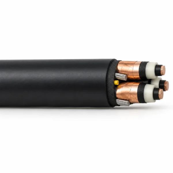
Type MP-GC EPR/CPE Mine Power Feeder Cable, 5–35 kV
Type MP-GC EPR-insulated cable for fixed mine power distribution. Three individually copper-tape-screened power cores, two earth conductors and an insulated ground-check core; CPE jacket at 5–35 kV, with separately specified EPR/PVC options at 25 and 35 kV.
Type MP-GC EPR/CPE mine feeder cable supplies fixed mine distribution circuits at 5, 8, 15, 25 and 35 kV. Its construction combines three individually screened copper power cores with two grounding conductors and an insulated ground-check conductor. EPR insulation and a thermosetting CPE jacket support permanent feeder connections between mine distribution equipment, including ducts, conduit, open air and suitably designed direct-burial routes. For a different material system, compare 15 kV MP-GC with XLPE insulation and a PVC jacket.
The ground-check core provides a separate circuit for the selected continuity-monitoring system; it does not replace the protective-earth conductors. Specify the feeder voltage, insulation level, conductor size and protection arrangement together. The published configurations use a 100% insulation level for grounded systems. Their current values also have different ambient-temperature bases: the 5–15 kV tables use 40°C, while the 25–35 kV tables use 30°C. Route conditions and installation grouping must be included in cable sizing.
This Class B feeder construction serves stationary distribution. For a moving shovel, dragline or continuously reeled machine circuit, compare SHD-GC cable for mobile mining equipment and specify the required movement duty. EPR/PVC variants at 25 and 35 kV are shown separately so the jacket and weight remain tied to the ordered construction. TEBAOFLEX supplies this family from a 50 m minimum order quantity, with a manufacturing lead time of 7–45 working days. Include the selected configuration, route and termination details with the enquiry.
Explore the mining and tunneling cable range for related configurations.
Construction
The representative MP-GC build has three screened power cores, two grounding conductors and one yellow-insulated ground-check conductor inside a taped round core. The CPE and PVC jacket variants retain separate ordering tables. The main image is a representative construction illustration.
| Component | Material and construction |
|---|---|
| Power conductors | Three stranded copper conductors in a Class B fixed-feeder construction. |
| Conductor screen | Extruded semiconducting layer over each power conductor. |
| Insulation | 90°C ethylene-propylene rubber (EPR); thickness follows the selected voltage table. |
| Insulation screen | Semiconducting layer beneath an individual copper-tape metallic screen on each power core. |
| Protective-earth conductors | Two uninsulated tinned-copper grounding conductors; their sizes are paired with the power conductors in each table. |
| Ground-check conductor | One 8 AWG, seven-wire copper conductor insulated with yellow polypropylene in the listed configurations. |
| Assembly | The three power cores, grounding conductors and ground-check core are assembled with fillers as required and a binder/taped core. |
| Outer jacket | Mould-cured thermosetting CPE for the 5–35 kV tables; PVC for the separate 25 and 35 kV EPR/PVC tables. Black is the standard reference colour. |
Applications
Select this family for permanent medium-voltage mine feeder routes. Coordinate the protective-earth and ground-check circuits with the mine distribution and protection design.
- Fixed connections between mine substations, distribution units and load centres.
- Duct, conduit and open-air feeder installations within the selected voltage rating.
- Direct-buried feeder circuits in wet or dry locations, with route-specific thermal and mechanical design.
- Supported vertical routes using a messenger and suitable mechanical support hardware; support spacing and tensile loads are design inputs.
- Replacement of an EPR-insulated MP-GC feeder where voltage, jacket material, ground-check wiring and termination dimensions match the equipment specification.
For route and construction selection, see the medium-voltage mining cable selection guide.
Specifications
| Parameter | Value |
|---|---|
| CPE-jacket voltage classes | 5, 8, 15, 25 and 35 kV |
| PVC-jacket EPR options | 25 and 35 kV; separate dimensions and weights |
| Insulation level in the tables | 100%, grounded-system reference |
| Maximum continuous conductor temperature | 90°C |
| Circuit arrangement | 3 power + 2 protective earth + 1 insulated ground check |
| Ground-check size in the tables | 8 AWG |
| Conductor duty | Class B fixed feeder; select a dedicated trailing design for continuous movement |
| Nominal outside-diameter tolerance | +8% / −5% for the tabulated reference constructions |
| Minimum order quantity | 50 m |
| Manufacturing lead time | 7–45 working days |
| Model and configuration: power + G + GC | EPR insulation (mils) | CPE jacket (mils) | Nominal OD (in.) | Approx. mass (lb/1,000 ft) | Ampacity (A) |
|---|---|---|---|---|---|
| Type MP-GC EPR/CPE 3 × 4 AWG + 2 × 8 AWG G + 1 × 8 AWG GC | 90 | 110 | 1.42 | 1441 | 122 |
| Type MP-GC EPR/CPE 3 × 2 AWG + 2 × 6 AWG G + 1 × 8 AWG GC | 90 | 110 | 1.56 | 1827 | 159 |
| Type MP-GC EPR/CPE 3 × 1 AWG + 2 × 5 AWG G + 1 × 8 AWG GC | 90 | 110 | 1.65 | 2168 | 184 |
| Type MP-GC EPR/CPE 3 × 1/0 AWG + 2 × 4 AWG G + 1 × 8 AWG GC | 90 | 110 | 1.76 | 2602 | 211 |
| Type MP-GC EPR/CPE 3 × 2/0 AWG + 2 × 3 AWG G + 1 × 8 AWG GC | 90 | 110 | 1.88 | 3010 | 243 |
| Type MP-GC EPR/CPE 3 × 4/0 AWG + 2 × 1 AWG G + 1 × 8 AWG GC | 90 | 140 | 2.14 | 4190 | 321 |
| Type MP-GC EPR/CPE 3 × 250 kcmil + 2 × 1/0 AWG G + 1 × 8 AWG GC | 90 | 140 | 2.23 | 4825 | 355 |
| Type MP-GC EPR/CPE 3 × 350 kcmil + 2 × 2/0 AWG G + 1 × 8 AWG GC | 90 | 140 | 2.47 | 6062 | 435 |
| Type MP-GC EPR/CPE 3 × 500 kcmil + 2 × 4/0 AWG G + 1 × 8 AWG GC | 90 | 140 | 2.70 | 8427 | 536 |
| Model and configuration: power + G + GC | EPR insulation (mils) | CPE jacket (mils) | Nominal OD (in.) | Approx. mass (lb/1,000 ft) | Ampacity (A) |
|---|---|---|---|---|---|
| Type MP-GC EPR/CPE 3 × 4 AWG + 2 × 8 AWG G + 1 × 8 AWG GC | 115 | 110 | 1.54 | 1608 | 122 |
| Type MP-GC EPR/CPE 3 × 2 AWG + 2 × 6 AWG G + 1 × 8 AWG GC | 115 | 110 | 1.66 | 1919 | 159 |
| Type MP-GC EPR/CPE 3 × 1 AWG + 2 × 5 AWG G + 1 × 8 AWG GC | 115 | 110 | 1.78 | 2507 | 184 |
| Type MP-GC EPR/CPE 3 × 1/0 AWG + 2 × 4 AWG G + 1 × 8 AWG GC | 115 | 110 | 1.89 | 2660 | 211 |
| Type MP-GC EPR/CPE 3 × 2/0 AWG + 2 × 3 AWG G + 1 × 8 AWG GC | 115 | 110 | 2.03 | 3257 | 243 |
| Type MP-GC EPR/CPE 3 × 4/0 AWG + 2 × 1 AWG G + 1 × 8 AWG GC | 115 | 140 | 2.28 | 4382 | 321 |
| Type MP-GC EPR/CPE 3 × 250 kcmil + 2 × 1/0 AWG G + 1 × 8 AWG GC | 115 | 140 | 2.31 | 4965 | 355 |
| Type MP-GC EPR/CPE 3 × 350 kcmil + 2 × 2/0 AWG G + 1 × 8 AWG GC | 115 | 140 | 2.58 | 6484 | 435 |
| Type MP-GC EPR/CPE 3 × 500 kcmil + 2 × 4/0 AWG G + 1 × 8 AWG GC | 115 | 140 | 2.88 | 8857 | 536 |
| Model and configuration: power + G + GC | EPR insulation (mils) | CPE jacket (mils) | Nominal OD (in.) | Approx. mass (lb/1,000 ft) | Ampacity (A) |
|---|---|---|---|---|---|
| Type MP-GC EPR/CPE 3 × 2 AWG + 2 × 6 AWG G + 1 × 8 AWG GC | 175 | 110 | 1.98 | 2517 | 164 |
| Type MP-GC EPR/CPE 3 × 1 AWG + 2 × 5 AWG G + 1 × 8 AWG GC | 175 | 110 | 2.11 | 3023 | 187 |
| Type MP-GC EPR/CPE 3 × 1/0 AWG + 2 × 4 AWG G + 1 × 8 AWG GC | 175 | 110 | 2.18 | 3296 | 215 |
| Type MP-GC EPR/CPE 3 × 2/0 AWG + 2 × 3 AWG G + 1 × 8 AWG GC | 175 | 110 | 2.30 | 3679 | 246 |
| Type MP-GC EPR/CPE 3 × 4/0 AWG + 2 × 1 AWG G + 1 × 8 AWG GC | 175 | 140 | 2.54 | 5146 | 325 |
| Type MP-GC EPR/CPE 3 × 250 kcmil + 2 × 1/0 AWG G + 1 × 8 AWG GC | 175 | 140 | 2.61 | 5618 | 359 |
| Type MP-GC EPR/CPE 3 × 350 kcmil + 2 × 2/0 AWG G + 1 × 8 AWG GC | 175 | 140 | 2.80 | 7055 | 438 |
| Type MP-GC EPR/CPE 3 × 500 kcmil + 2 × 4/0 AWG G + 1 × 8 AWG GC | 175 | 170 | 3.15 | 9405 | 536 |
| Model and configuration: power + G + GC | EPR insulation (mm) | CPE jacket (mm) | Nominal OD (mm) | Approx. mass (kg/km) | Ampacity (A) |
|---|---|---|---|---|---|
| Type MP-GC EPR/CPE 3 × 1 AWG + 2 × 5 AWG G + 1 × 8 AWG GC | 6.60 | 3.6 | 61.5 | 5302 | 210 |
| Type MP-GC EPR/CPE 3 × 1/0 AWG + 2 × 4 AWG G + 1 × 8 AWG GC | 6.60 | 3.6 | 63.7 | 5918 | 240 |
| Type MP-GC EPR/CPE 3 × 2/0 AWG + 2 × 3 AWG G + 1 × 8 AWG GC | 6.60 | 4.3 | 66.1 | 6688 | 274 |
| Type MP-GC EPR/CPE 3 × 3/0 AWG + 2 × 2 AWG G + 1 × 8 AWG GC | 6.60 | 4.3 | 68.9 | 7704 | 315 |
| Type MP-GC EPR/CPE 3 × 4/0 AWG + 2 × 1 AWG G + 1 × 8 AWG GC | 6.60 | 4.3 | 73.5 | 8881 | 360 |
| Type MP-GC EPR/CPE 3 × 250 kcmil + 2 × 1/0 AWG G + 1 × 8 AWG GC | 6.60 | 4.3 | 76.0 | 9814 | 396 |
| Type MP-GC EPR/CPE 3 × 350 kcmil + 2 × 2/0 AWG G + 1 × 8 AWG GC | 6.60 | 4.3 | 81.7 | 12262 | 482 |
| Type MP-GC EPR/CPE 3 × 500 kcmil + 2 × 3/0 AWG G + 1 × 8 AWG GC | 6.60 | 4.3 | 88.8 | 15369 | 590 |
| Model and configuration: power + G + GC | EPR insulation (mm) | CPE jacket (mm) | Nominal OD (mm) | Approx. mass (kg/km) | Ampacity (A) |
|---|---|---|---|---|---|
| Type MP-GC EPR/CPE 3 × 1/0 AWG + 2 × 4 AWG G + 1 × 8 AWG GC | 8.76 | 4.3 | 73.4 | 7452 | 240 |
| Type MP-GC EPR/CPE 3 × 2/0 AWG + 2 × 3 AWG G + 1 × 8 AWG GC | 8.76 | 4.3 | 76.3 | 8256 | 274 |
| Type MP-GC EPR/CPE 3 × 3/0 AWG + 2 × 2 AWG G + 1 × 8 AWG GC | 8.76 | 4.3 | 78.9 | 9223 | 315 |
| Type MP-GC EPR/CPE 3 × 4/0 AWG + 2 × 1 AWG G + 1 × 8 AWG GC | 8.76 | 4.3 | 81.9 | 10312 | 360 |
| Type MP-GC EPR/CPE 3 × 250 kcmil + 2 × 1/0 AWG G + 1 × 8 AWG GC | 8.76 | 4.3 | 84.7 | 11289 | 396 |
| Type MP-GC EPR/CPE 3 × 350 kcmil + 2 × 2/0 AWG G + 1 × 8 AWG GC | 8.76 | 5.1 | 91.8 | 14173 | 482 |
| Type MP-GC EPR/CPE 3 × 500 kcmil + 2 × 3/0 AWG G + 1 × 8 AWG GC | 8.76 | 5.1 | 98.9 | 17818 | 590 |
| Model and configuration: power + G + GC | EPR insulation (mm) | PVC jacket (mm) | Nominal OD (mm) | Approx. mass (kg/km) | Ampacity (A) |
|---|---|---|---|---|---|
| Type MP-GC EPR/PVC 3 × 1 AWG + 2 × 5 AWG G + 1 × 8 AWG GC | 6.60 | 3.6 | 61.5 | 4673 | 210 |
| Type MP-GC EPR/PVC 3 × 1/0 AWG + 2 × 4 AWG G + 1 × 8 AWG GC | 6.60 | 3.6 | 63.7 | 5256 | 240 |
| Type MP-GC EPR/PVC 3 × 2/0 AWG + 2 × 3 AWG G + 1 × 8 AWG GC | 6.60 | 4.3 | 66.1 | 6025 | 274 |
| Type MP-GC EPR/PVC 3 × 3/0 AWG + 2 × 2 AWG G + 1 × 8 AWG GC | 6.60 | 4.3 | 68.9 | 6894 | 315 |
| Type MP-GC EPR/PVC 3 × 4/0 AWG + 2 × 1 AWG G + 1 × 8 AWG GC | 6.60 | 4.3 | 73.5 | 8026 | 360 |
| Type MP-GC EPR/PVC 3 × 250 kcmil + 2 × 1/0 AWG G + 1 × 8 AWG GC | 6.60 | 4.3 | 76.0 | 8925 | 396 |
| Type MP-GC EPR/PVC 3 × 350 kcmil + 2 × 2/0 AWG G + 1 × 8 AWG GC | 6.60 | 4.3 | 81.7 | 11315 | 482 |
| Type MP-GC EPR/PVC 3 × 500 kcmil + 2 × 3/0 AWG G + 1 × 8 AWG GC | 6.60 | 4.3 | 88.8 | 14055 | 590 |
| Model and configuration: power + G + GC | EPR insulation (mm) | PVC jacket (mm) | Nominal OD (mm) | Approx. mass (kg/km) | Ampacity (A) |
|---|---|---|---|---|---|
| Type MP-GC EPR/PVC 3 × 1/0 AWG + 2 × 4 AWG G + 1 × 8 AWG GC | 8.76 | 4.3 | 73.4 | 6486 | 240 |
| Type MP-GC EPR/PVC 3 × 2/0 AWG + 2 × 3 AWG G + 1 × 8 AWG GC | 8.76 | 4.3 | 76.3 | 7221 | 274 |
| Type MP-GC EPR/PVC 3 × 3/0 AWG + 2 × 2 AWG G + 1 × 8 AWG GC | 8.76 | 4.3 | 78.9 | 8077 | 315 |
| Type MP-GC EPR/PVC 3 × 4/0 AWG + 2 × 1 AWG G + 1 × 8 AWG GC | 8.76 | 4.3 | 81.9 | 9196 | 360 |
| Type MP-GC EPR/PVC 3 × 250 kcmil + 2 × 1/0 AWG G + 1 × 8 AWG GC | 8.76 | 4.3 | 84.7 | 10107 | 396 |
| Type MP-GC EPR/PVC 3 × 350 kcmil + 2 × 2/0 AWG G + 1 × 8 AWG GC | 8.76 | 5.1 | 91.8 | 12785 | 482 |
| Type MP-GC EPR/PVC 3 × 500 kcmil + 2 × 3/0 AWG G + 1 × 8 AWG GC | 8.76 | 5.1 | 98.9 | 15976 | 590 |
G identifies each protective-earth conductor; GC identifies the insulated ground-check conductor. The first three equal conductors are the power cores.
Select dimensions from the table for the ordered voltage and jacket material; dimensions for one voltage class must not be used for another.
The 5, 8 and 15 kV tables retain inch/mil and lb/1,000 ft units. The 25 and 35 kV tables use millimetres and kg/km. One mil is 0.001 inch.
Ampacities use a 90°C conductor temperature: 40°C ambient for the 5–15 kV tables and 30°C ambient for the 25–35 kV tables. Apply the installation, grouping and ambient conditions when calculating the circuit rating.
Dimensions and masses are nominal reference values. Use the quoted configuration and outside-diameter tolerance when selecting glands, supports and terminations.
The EPR/PVC tables are distinct from XLPE/PVC MP-GC constructions. Insulation material, jacket material and voltage must all appear on the order specification.
A vertical installation requires its own support arrangement and allowable-load check; the cable is not specified here for unrestricted unsupported shaft suspension.
Where a different insulation level or a three-earth-conductor arrangement is required, identify it separately in the enquiry; the listed two-earth-plus-ground-check tables do not define those configurations.
Standards
| Standard or specification | Application |
|---|---|
| ICEA S-75-381 / NEMA WC-58 | Mine power-feeder design reference for the 5–25 kV constructions. |
| ASTM B8 | Concentric-lay stranded copper-conductor construction reference. |
| ASTM B33 | Tin-coated copper-wire reference for the grounding-conductor construction. |
| CSA C22.2 No. 96.1 | Mine power-feeder cable design and test reference; the selected voltage and construction identify the applicable requirements. |
Official standards and approval references
The current NEMA/ICEA publication uses NEMA WC 23058 in place of the historical WC 58 designation. The CSA record identifies C22.2 No. 96.1-16 (R2026). Keep the voltage, insulation level and jacket selection tied to the separate configuration tables on this page.
- CSA C22.2 No. 96.1 — Mine power feeder cables — Official record for fixed or semi-fixed mine feeder constructions, including 5, 8, 15, 25 and 35 kV voltage classes.
- ANSI/NEMA WC 23058 / ICEA S-75-381 — Current standard publication for portable and power-feeder cables used in mines and similar applications.
Certifications and document support
Review our company certificates and document scopes when identifying the documentation required for the quoted construction.
For certificate or acceptance-document review, identify the voltage class, insulation level, EPR insulation, CPE or PVC jacket, conductor sizes and ground-check arrangement. A record for one voltage or material system must be matched to its stated scope before it is used for another construction. Include the specified approval body and marking requirements with the order enquiry.
Related cable options
Compare these cable options by service combination, movement, load, voltage and transmission requirement.
Type MP-GC 15kV Mine Power Feeder Cable
A related cable option for a different application or duty profile.
View product
Type MV-105 EPR Copper-Tape-Screened Distribution Cable, 15 kV and 35 kV
A related cable option for a different application or duty profile.
View product
SHD-GC Cable 2kV-25kV Mining Power Cable
A related cable option for a different application or duty profile.
View productRequest a cable recommendation and quotation
Send the required services, cable length, mechanical duty, environment, termination and quantity. Our team will review the application before quoting.
- Include the product name or SKU plus the required cable length and quantity.
- Attach a specification, drawing or data sheet when available.