









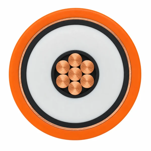


5 kV XLPE Airfield Lighting Cable — Tape and Braid Screens
Single-core 5 kV airfield lighting cable for primary series circuits, with class 2 bare copper, semiconductive layers, XLPE insulation and a metallic screen. Standard PE and extra-hard AT sheath constructions are listed separately, including a specific tinned-braid option.
5 kV airfield lighting cable supplies the primary series circuit between the constant-current regulator and airfield lighting transformers. The screened single-core construction is intended for fixed installation in conduits and trenches serving runways, taxiways, approach lighting and apron signs. Its electrical function and voltage class are selected as part of the lighting circuit.
A class 2 stranded copper conductor, inner semiconductive layer, XLPE insulation and outer semiconductive layer form the voltage-control system. A metallic screen surrounds the insulation, followed by a halogen-free PE outer sheath. The standard range uses longitudinal copper or brass tape. The extra-hard AT range retains its own tape-screen options and adds a specific tinned-copper-braid construction.
Compare each complete configuration in the tables. The 6 mm² and 8 AWG versions differ in conductor resistance, diameter, screen resistance and capacitance; copper and brass screens also carry different resistance values. The braid-screen AT version has its own fixed bending limit and flame-test reference, which remain attached to that construction.
Provide the primary circuit specification, conductor size, screen type, cable length, duct or trench arrangement and termination drawing with the enquiry. TEBAOFLEX can prepare the cable selection around those installation requirements, the specified airfield-lighting standard and the operating environment.
Explore the industrial cable range for related configurations.
For airport apron servicing and static aviation feeder circuits operating alongside runway lighting loops, compare these cables: 270 V DC Aircraft Ground Power Cable — Power and Control (for 270 V DC flexible apron ground power and pilot interlock assemblies); 400Hz Feeder Cable | LSOH Static Aviation Power (for fixed LSOH 400 Hz AC sub-apron feeders supplying gate transformers and bridge converters). Verify constant-current regulator output voltage, screen earthing method, and duct burial conditions before ordering.
Construction
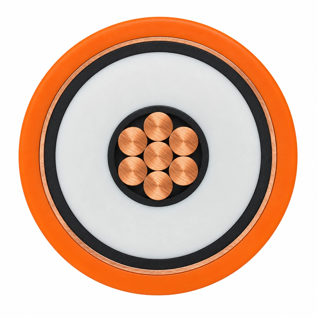
The representative image shows the standard 5 kV, 1 × 6 mm² construction with seven copper strands, two semiconductive layers, 2.5 mm nominal XLPE insulation, one longitudinal copper-tape screen and an orange PE sheath. Other screen and sheath variants remain separately identified in the tables.
| Component | Material and construction |
|---|---|
| Conductor | One bare stranded copper conductor, IEC 60228 class 2; seven strands in the listed 6 mm² and 8 AWG configurations. |
| Inner semiconductive layer | Extruded layer over the conductor. |
| Insulation | Cross-linked polyethylene, XLPE; nominal thickness 2.5 mm. |
| Outer semiconductive layer | Semiconductive tape or extruded semiconductive layer. |
| Metallic screen | Longitudinal copper or brass tape. The specified 6 mm² AT braid version uses tinned fine copper braid with >85% coverage. |
| Outer sheath | Halogen-free PE. Standard sheath or extra-hard AT sheath for the selected environmental requirement; orange or black as specified. |
Applications
Use the 5 kV screened construction on the primary series side of an airfield lighting system. Match the cable screen, conductor and connector system to the constant-current circuit and the installation drawing.

- Primary connections between constant-current regulators and series-connected airfield lighting transformers.
- Fixed runway, taxiway, touchdown-zone, approach-lighting and apron-sign circuits in conduits or trenches.
- Airport installations exposed to aviation hydraulic fluid, de-icing fluid, oil, fuel, water and dilute acids or alkalis, with the specified PE sheath.
- AT sheath configurations where an extra-hard jacket is required for termite and rodent exposure.
- The listed AT tinned-braid construction where the project requires its tighter static bend and flame-test reference.
- Select primary and secondary lighting cables separately and provide the specified connector kit, circuit voltage, screen bonding arrangement and installation conditions with the enquiry.
For complete airside power distribution and low-voltage auxiliary trench circuits, review these specifications: Airport Ground Power Cable Solutions for GPU, FEGP & PCA (covering airside GPU, FEGP, and gate power infrastructure); NYY Cable 0.6/1 kV Copper PVC Power Cable (for 0.6/1 kV fixed underground PVC power distribution to airside Vault buildings and perimeter signage). Check soil thermal resistivity, conduit pulling tension, and outer sheath chemical resistance.
Specifications
| Parameter | Value |
|---|---|
| Rated voltage | U₀ = 5000 V. |
| Primary application | Fixed primary series circuits for airfield lighting. |
| Conductor sizes | 1 × 6 mm² RM or 1 × 8 AWG RM, seven strands. |
| Insulation | XLPE, nominal 2.5 mm, with inner and outer semiconductive layers. |
| Screen options | Longitudinal copper tape, longitudinal brass tape, or the specified AT tinned-copper braid. |
| Operating temperature | −40 to +90°C. |
| Minimum static bending radius | >9 × D; >6 × D for the specified AT 6 mm² tinned-braid construction. |
| Configuration | Conductor strands | Overall diameter (mm) | Nominal insulation (mm) | Screen construction | Approx. mass (kg/km) | Conductor resistance (Ω/km) | Screen resistance (Ω/km) | Capacitance (μF/km) |
|---|---|---|---|---|---|---|---|---|
| 5 kV standard 1 × 6 mm² RM — copper tape | 7 | 12.5 | 2.5 | Copper tape, longitudinal | 187 | ≤3.08 | ≤5.90 | 0.157 |
| 5 kV standard 1 × 8 AWG RM — copper tape | 7 | 13.0 | 2.5 | Copper tape, longitudinal | 212 | ≤2.10 | ≤5.25 | 0.181 |
| 5 kV standard 1 × 6 mm² RM — brass tape | 7 | 12.5 | 2.5 | Brass tape, longitudinal | 185 | ≤3.08 | ≤18.40 | 0.157 |
| 5 kV standard 1 × 8 AWG RM — brass tape | 7 | 13.0 | 2.5 | Brass tape, longitudinal | 210 | ≤2.10 | ≤19.50 | 0.181 |
| Configuration | Conductor strands | Overall diameter (mm) | Nominal insulation (mm) | Screen construction | Approx. mass (kg/km) | Conductor resistance (Ω/km) | Screen resistance (Ω/km) | Capacitance (μF/km) |
|---|---|---|---|---|---|---|---|---|
| 5 kV AT 1 × 6 mm² RM — copper tape | 7 | 12.5 | 2.5 | Copper tape, longitudinal | 195 | ≤3.08 | ≤5.90 | 0.157 |
| 5 kV AT 1 × 8 AWG RM — copper tape | 7 | 13.4 | 2.5 | Copper tape, longitudinal | 220 | ≤2.10 | ≤5.25 | 0.181 |
| 5 kV AT 1 × 6 mm² RM — tinned copper braid | 7 | 13.3 | 2.5 | Tinned fine copper braid, >85% coverage | Specify with enquiry | ≤3.08 | ≤5.00 | 0.157 |
| 5 kV AT 1 × 6 mm² RM — brass tape | 7 | 12.9 | 2.5 | Brass tape, longitudinal | 193 | ≤3.08 | ≤18.40 | 0.157 |
| Condition | Specified value / scope |
|---|---|
| Nominal voltage | U₀ = 5000 V |
| Voltage test | 20000 V AC, IEC TS 62100 reference |
| Partial-discharge test reference | 5000 V; no partial discharge stated in the reference construction |
| Operating temperature | −40 to +90°C |
| Minimum fixed bend, tape-screen constructions | >9 × D |
| Minimum fixed bend, AT 6 mm² tinned-braid construction | >6 × D |
| Flame-test reference, AT 6 mm² tinned-braid construction | IEC 60332-1 |
RM identifies the round stranded conductor form. Keep 6 mm² and 8 AWG designations separate in the enquiry; neither is substituted for the other in the tables.
D is the finished cable outside diameter. The smaller >6 × D static bending limit belongs only to the listed AT tinned-braid construction; the tape-screen versions use >9 × D.
Select the screen resistance with the screen material and construction. The capacitance values describe each complete listed cable configuration.
The 20000 V AC value is a voltage-test reference, separate from the 5000 V nominal rating. Specify the project test plan and required standard edition with the enquiry.
Coordinate the connector kit with conductor form, insulation diameter, screen treatment and the circuit drawing. Seal cable ends against moisture during storage and installation.
Select flame performance, water-blocking measures and sheath colour with the installation requirements. The standard PE and AT configurations keep their individual construction details.
Standards
| Standard or specification | Application |
|---|---|
| IEC 60228 class 2 | Round stranded copper conductor construction. |
| FAA L-824 Type C | Airfield primary-circuit cable construction reference. Specify the required AC 150/5345-7 edition and project documentation with the enquiry. |
| IEC TS 62100 | Airfield lighting cable test reference, including the listed 20000 V AC voltage test. |
| IEC 60754-1 / EN 50267-2-1 | Halogen-acid-gas content references for the sheath material. |
| IEC 60754-2 / EN 50267-2-2 | Acidity and conductivity test references for gases released during combustion. |
| NES 02-713 / NFC 20-454 | Combustion-gas toxicity test references. |
| IEC 60332-1 | Flame-test reference for the specified AT 6 mm² tinned-copper-braid construction. |
| FAA L-823 Type 1 | Connector-system selection reference for the project termination interface. |
FAA specification for L-824 underground airport lighting cable
Related cable options
Compare these cable options by service combination, movement, load, voltage and transmission requirement.
H07RN-F Cable 450/750 V Heavy-Duty Rubber Flexible Cable
A related cable option for a different application or duty profile.
View product
NYY Cable 0.6/1 kV Copper PVC Power Cable
A related cable option for a different application or duty profile.
View productRequest a cable recommendation and quotation
Send the required services, cable length, mechanical duty, environment, termination and quantity. Our team will review the application before quoting.
- Include the product name or SKU plus the required cable length and quantity.
- Attach a specification, drawing or data sheet when available.