











BFOU VFD 1.8/3 kV Offshore Cable — 3C+3E LSZH
Fire-resistant LSZH offshore VFD power cable, rated 1.8/3 kV, with three phase cores and three split earth conductors. Class 2 BFOU VFD and Class 5 FX-BFOU VFD sizes from 3 × 10 + 3E × 4 to 3 × 240 + 3E × 50 mm².
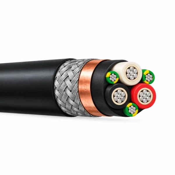
BFOU VFD 1.8/3 kV cable is a fire-resistant, low-smoke halogen-free power cable for fixed marine and offshore variable-frequency-drive motor circuits. Its three phase cores and three smaller earth conductors form a symmetrical 3C+3E arrangement beneath a copper/polyester tape screen and tinned copper wire braid. The construction combines a mica/glass fire barrier, EPR insulation, halogen-free bedding and a black SHF2 outer sheath.
The 1.8/3 kV insulation rating identifies the cable’s electrical design; drive output voltage, motor-terminal voltage stress, route length and termination requirements remain part of cable selection. The three distributed earth conductors provide a symmetrical protective-conductor layout. The continuous tape screen and metallic braid support EMC bonding when the cable glands and equipment connections are installed for the complete drive system.
Choose BFOU VFD with Class 2 stranded conductors or FX-BFOU VFD with Class 5 flexible conductors. Both size schedules cover 3 × 10 + 3E × 4 mm² through 3 × 240 + 3E × 50 mm², with separate diameters and weights. Class 5 is an alternative conductor construction for routing and termination; installation movement and bend duty should be specified with the enquiry. Select standard SHF2 or the mud-resistant sheath option to match the exposure along the actual cable route.
For related marine and offshore selections, explore the marine and offshore cable range for other shipboard power, instrumentation and drive connections.
For selection by fire performance and screening, see the RFOU vs BFOU cable guide.
Construction
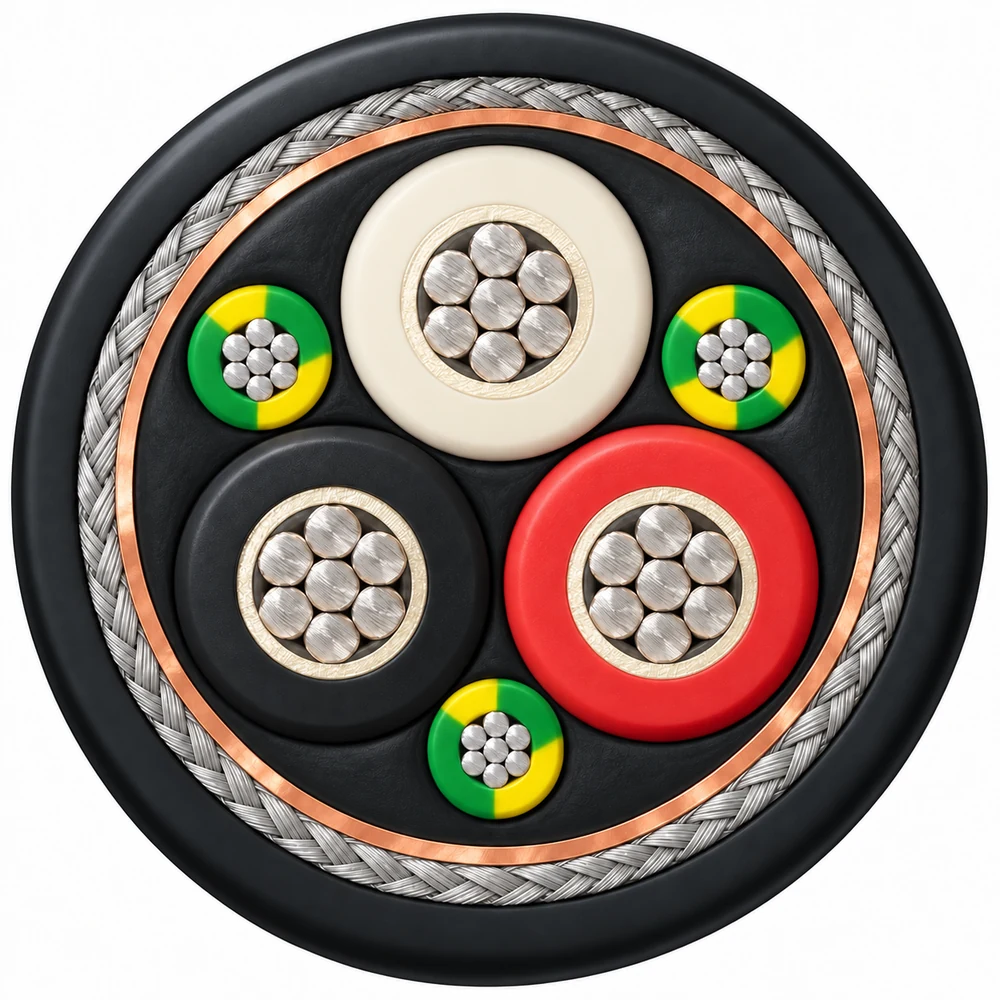
The representative illustration shows BFOU VFD 3 × 25 + 3E × 6 mm²: three phase cores in a trefoil arrangement, with one smaller earth core in each outer interstice. The layers and conductor positions are the same in the product cutaway and cross-section.
| Component | Material and arrangement |
|---|---|
| Phase conductors | Three stranded tinned annealed copper conductors, IEC 60228 Class 2; FX-BFOU VFD uses Class 5 flexible conductors. |
| Fire barrier | Mica/glass tape around the phase conductors beneath the insulation. |
| Phase insulation | Halogen-free ethylene propylene rubber (EPR). |
| Earth conductors | Three smaller stranded tinned copper conductors, distributed symmetrically between the phase cores. Each earth conductor's cross-section is listed separately in the size tables. |
| Inner covering | Flame-retardant halogen-free bedding around the laid-up cores. |
| Tape screen | Copper/polyester (Cu/PS) tape with 100% coverage. |
| Braid armour | Tinned annealed copper wire braid; bronze wire braid is an alternative construction. |
| Outer sheath | Black SHF2 sheath; SHF-Mud compound is available for the specified mud-resistant construction. |
Applications
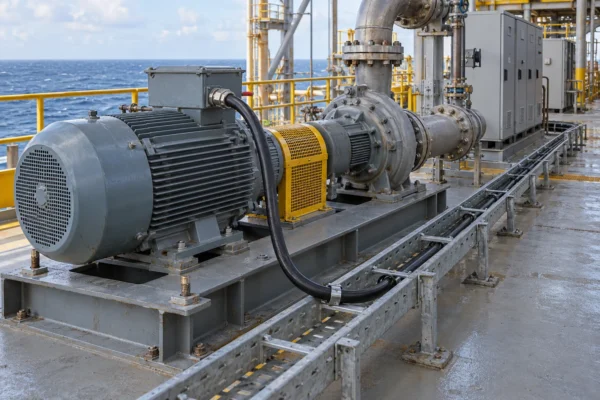
For fixed power connections between variable frequency drives and AC motors aboard ships and on offshore installations. Typical routes include cable trays, equipment skids and protected connections to pumps, fans and other driven auxiliaries.
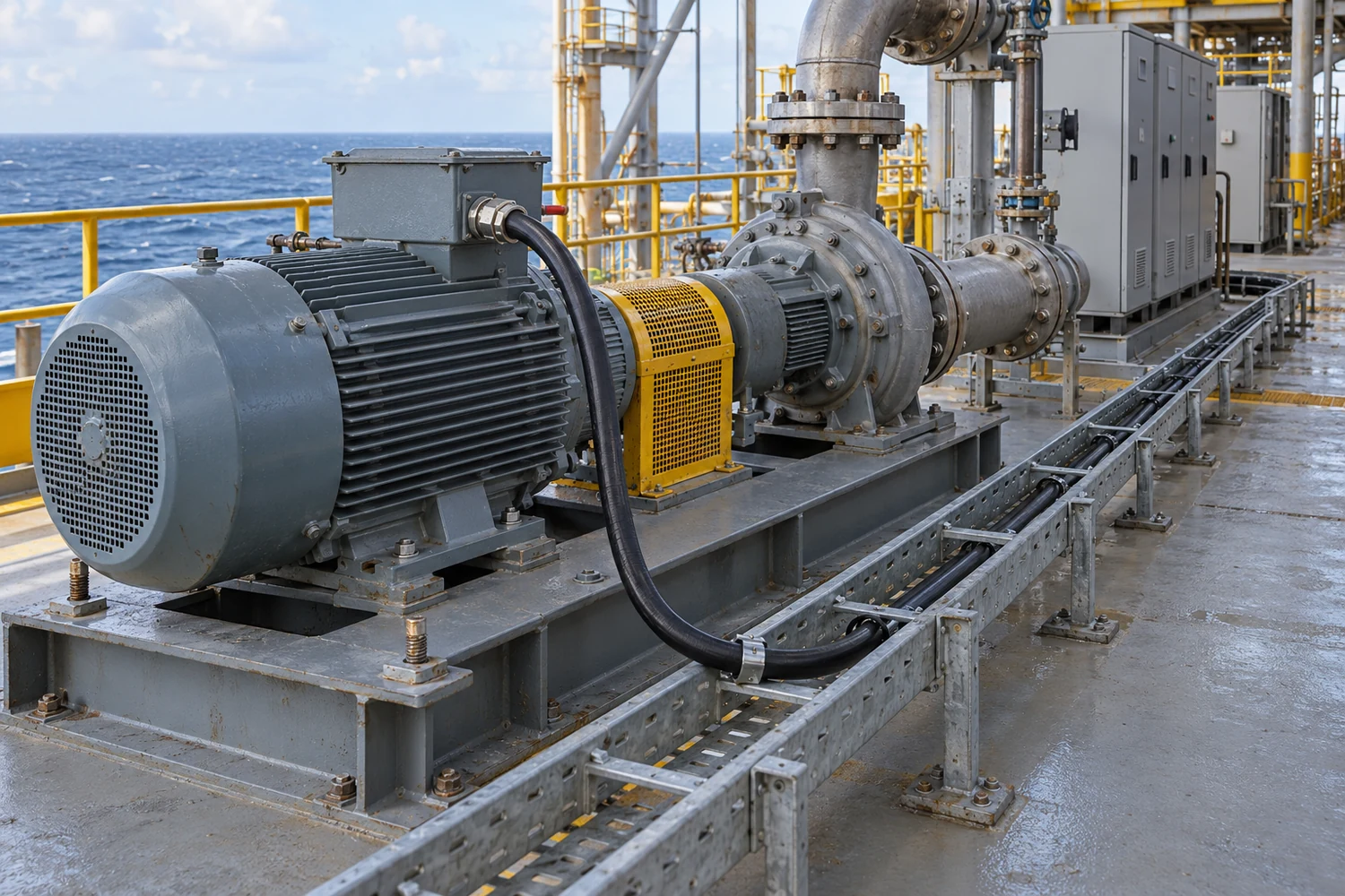
- Shipboard and offshore VFD motor feeders requiring an LSZH, fire-resistant construction.
- Drive circuits requiring a symmetrical three-phase and split-earth arrangement with an overall metallic screen and braid.
- Oil and gas installations where the selected outer-sheath compound must match oil or drilling-fluid exposure.
Match the conductor class, gland and screen termination, motor circuit, installation bend radius and fire-test requirement to the equipment specification. Specify mud-resistant or Arctic construction when required by the project.
Specifications
| Parameter | Specification |
|---|---|
| Rated voltage U₀/U | 1.8/3 kV |
| Conductor temperature | 90°C maximum |
| Core arrangement | 3 phase cores + 3 split earth conductors (3C+3E) |
| Conductor options | Class 2 BFOU VFD; Class 5 FX-BFOU VFD |
| Phase conductor range | 10–240 mm² in the schedules below |
| Halogen-content reference | IEC 60754-1, ≤0.5% |
| Smoke-transmittance reference | IEC 61034, >60% |
| Cold bend / cold impact | −40°C / −35°C test references; Arctic option −65°C / −65°C |
| Sheath options | Black SHF2; mud-resistant SHF-Mud by specified construction |
The current ratings below use 45°C ambient temperature and 90°C conductor temperature, based on IEC 60092-352 Table B.4. Apply the installation and grouping corrections for the actual route. Diameters and weights are nominal values subject to manufacturing tolerances.
BFOU VFD — Class 2
| Model and configuration (mm²) | Nominal OD (mm) | Approx. weight (kg/km) | Current rating (A) |
|---|---|---|---|
| BFOU VFD 3 × 10 + 3E × 4 mm² | 29.4 | 1,410 | 50 |
| BFOU VFD 3 × 16 + 3E × 6 mm² | 31.8 | 1,760 | 67 |
| BFOU VFD 3 × 25 + 3E × 6 mm² | 33.0 | 2,070 | 89 |
| BFOU VFD 3 × 35 + 3E × 6 mm² | 36.6 | 2,630 | 110 |
| BFOU VFD 3 × 50 + 3E × 10 mm² | 39.8 | 3,270 | 137 |
| BFOU VFD 3 × 70 + 3E × 16 mm² | 44.1 | 4,300 | 169 |
| BFOU VFD 3 × 95 + 3E × 16 mm² | 49.8 | 5,490 | 205 |
| BFOU VFD 3 × 120 + 3E × 25 mm² | 53.5 | 6,690 | 237 |
| BFOU VFD 3 × 150 + 3E × 25 mm² | 57.7 | 7,800 | 273 |
| BFOU VFD 3 × 185 + 3E × 35 mm² | 62.0 | 9,420 | 311 |
| BFOU VFD 3 × 240 + 3E × 50 mm² | 68.2 | 11,900 | 366 |
FX-BFOU VFD — Class 5
| Model and configuration (mm²) | Nominal OD (mm) | Approx. weight (kg/km) | Current rating (A) |
|---|---|---|---|
| FX-BFOU VFD 3 × 10 + 3E × 4 mm² | 29.8 | 1,450 | 50 |
| FX-BFOU VFD 3 × 16 + 3E × 6 mm² | 33.8 | 1,900 | 67 |
| FX-BFOU VFD 3 × 25 + 3E × 6 mm² | 35.7 | 2,240 | 89 |
| FX-BFOU VFD 3 × 35 + 3E × 6 mm² | 39.4 | 2,840 | 110 |
| FX-BFOU VFD 3 × 50 + 3E × 10 mm² | 43.0 | 3,640 | 137 |
| FX-BFOU VFD 3 × 70 + 3E × 16 mm² | 49.4 | 4,870 | 169 |
| FX-BFOU VFD 3 × 95 + 3E × 16 mm² | 53.0 | 5,770 | 205 |
| FX-BFOU VFD 3 × 120 + 3E × 25 mm² | 58.6 | 7,210 | 237 |
| FX-BFOU VFD 3 × 150 + 3E × 25 mm² | 61.8 | 8,300 | 273 |
| FX-BFOU VFD 3 × 185 + 3E × 35 mm² | 66.3 | 9,840 | 311 |
| FX-BFOU VFD 3 × 240 + 3E × 50 mm² | 75.2 | 12,830 | 366 |
In each configuration, 3E × 6 mm², for example, means three individual earth conductors of 6 mm² each. It does not mean a total earth cross-section of 6 mm².
Standards
| Reference | Scope |
|---|---|
| NEK 606; IEC 60092-353 | Marine and offshore power-cable design references. |
| IEC 60228 | Class 2 stranded conductors; Class 5 for FX construction. |
| IEC 60092-360 | Insulation and sheathing materials. |
| IEC 60332-1; IEC 60332-3 Category A | Flame-retardance test references. |
| IEC 60331-1 / -2 / -21 | Fire-resistance and circuit-integrity test references; specify the required method with the project. |
| IEC 60754-1; IEC 61034 | Halogen content and smoke transmittance. |
| NEK 606 | Mud-resistance reference for the specified mud-resistant sheath. |
| CSA C22.2 No. 03 | Cold-bend and cold-impact test references. |
For the offshore cable specification, see the NEK TS 606 official overview. State the project edition and required fire-test method with the enquiry.
Related cable options
Compare these cable options by service combination, movement, load, voltage and transmission requirement.
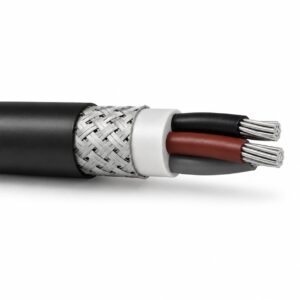
NEK 606 BFOU Cable | P5/P12 Power & Instrumentation
A related cable option for a different application or duty profile.
View product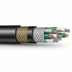
Type P VFD Cable 2000V 1/0 AWG to 777 MCM Unarmored
A related cable option for a different application or duty profile.
View product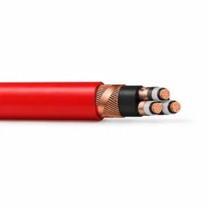
Medium Voltage VFD Motor Cable — 3GSEGCH / 3GSEGCY
A related cable option for a different application or duty profile.
View productRequest a cable recommendation and quotation
Send the required services, cable length, mechanical duty, environment, termination and quantity. Our team will review the application before quoting.
- Include the product name or SKU plus the required cable length and quantity.
- Attach a specification, drawing or data sheet when available.