











High Voltage Coaxial Cable — PE-X, FEP and PE Configurations
Single-centre high voltage coaxial cable with a concentric metallic screen. PE-X, FEP and PE constructions cover reference duties from 10 to 50 kV DC, with AC ratings, dimensions, impedance and bend limits specified separately by configuration.
High voltage coaxial cable connects high-voltage equipment through one central conductor, a dielectric layer and a concentric metallic screen. This range covers PE-X, FEP and PE constructions for equipment wiring, instrument connections and test systems. Reference configurations span 10–50 kV DC; the listed AC operating ratings apply only to their named constructions.
Choose the electrical duty before choosing the outer diameter. An RG58-size PE-X design combines a 0.50 mm² conductor, approximately 51 Ω impedance and a compact red jacket. The FEP alternatives provide smaller or higher-temperature connections, while the 3.1 mm² PE/PVC RG213-size construction offers a larger centre conductor. The PE-X high-voltage designs include different screen and jacket arrangements at 30, 40 and 50 kV DC.
The tables separate material, dimensions, resistance, capacitance, bend radius and electrical tests so each configuration can be assessed as a complete cable. A spark-test voltage describes a manufacturing test; use the stated DC or AC operating rating when selecting the connection. Connector dimensions, working voltage and dielectric preparation must be selected together with the cable.
Use the reference configuration in the enquiry together with the voltage waveform, required length, operating temperature and termination drawing. Indicate whether the route is fixed or involves occasional repositioning, and provide the available bend space. TEBAOFLEX will prepare the cable quotation around these equipment and installation requirements.
Explore the high voltage DC and test cable range for related configurations.
For related guarded triaxial measurement cables and flexible silicone-insulated DC shielded leads, compare these constructions: High Voltage Triaxial Cable — Guarded Measurement and Test Configurations (for dual-screened triaxial assemblies that cancel stray surface leakage during microampere HV testing); Shielded Silicone High Voltage Cable, 8–15 kV DC (for extra-flexible 8–15 kV DC tinned-copper braided silicone leads). Confirm dielectric material (PE-X, FEP, or solid PE), semiconductive layer geometry, and peak DC voltage before ordering.
Construction
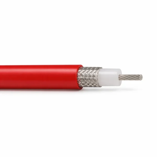
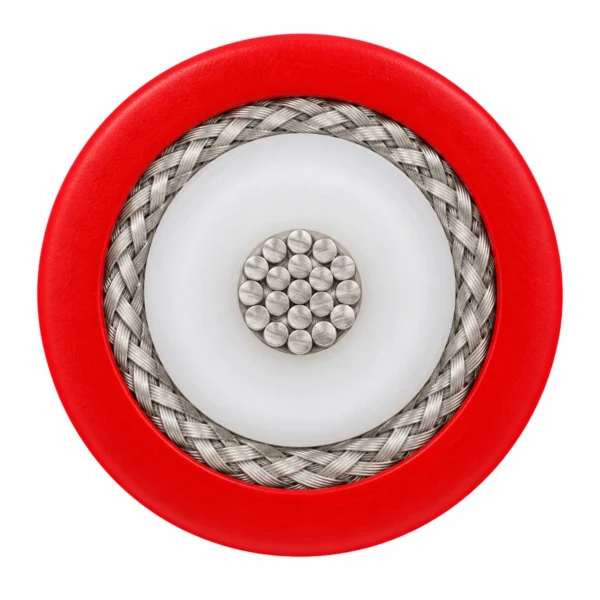
The illustration represents the 20 kV DC, 0.50 mm² PE-X/PUR coaxial configuration: one stranded centre conductor, one PE-X dielectric, one tinned-copper braid and a red PUR jacket. Other constructions have the material and dimensional differences listed below.

| Component | Material and construction |
|---|---|
| Centre conductor | Tinned copper strands in the PE-X configurations; silver-plated copper in the FEP configurations; bare copper in the PE/PVC RG213-size configuration. The conductor is one central electrical path. |
| Main dielectric | Concentric PE-X, FEP or PE insulation. Its material and overall diameter are specific to the selected reference configuration. |
| Metallic screen | One concentric braid or served wire screen around the dielectric system. The illustrated RG58-size construction uses a 90% coverage tinned-copper braid. |
| Additional voltage-control or insulation layers | The 40 kV PE-X/PUR configuration adds a semiconductive PE conductor layer. The 50 kV PE-X/PVC construction has a red PVC inner jacket inside its helically served screen. |
| Outer jacket | PUR, PE-X, FEP or PVC as listed by configuration. Jacket material is selected with temperature, chemical environment, routing and termination requirements. |
Applications
Select the cable for the actual voltage system, equipment connection and routing space. The screened construction provides a concentric return or shielding path as defined by the equipment circuit.

- High-voltage power-supply and instrument connections using a screened single-centre cable.
- Laboratory and equipment test connections where outer diameter, capacitance and impedance are part of the circuit design.
- Compact RG58-size or RG316-size equipment wiring when the specified high-voltage construction and matching termination are required.
- FEP-insulated connections where the selected configuration requires a −65 to +200°C material operating range.
- Fixed wiring and occasional repositioning with the bend radius appropriate to the named construction; repeated-motion duty is specified with the equipment brief.
- Provide DC or AC duty, frequency, pulse conditions where relevant, temperature, bend space and the connector drawing with the enquiry.
For custom high-voltage DC silicone cable engineering and unshielded crosslinked polyethylene lead wires, review: High Voltage Silicone Cable Manufacturer (for custom DC voltage ratings, corona-control layers, and multi-core HV silicone assemblies); XLPE / PE-X High Voltage Wire, 3–50 kV DC (for compact unshielded 3–50 kV DC XLPE / PE-X internal chassis and power-supply wiring). Verify characteristic capacitance, pulse repetition rate, and HV connector compatibility during system design.
Specifications
| Parameter | Value |
|---|---|
| Cable arrangement | One centre conductor and one concentric metallic screen. |
| Rated voltage, DC operation | 10, 20, 30, 40 or 50 kV DC, by reference configuration. |
| AC operating voltage | 1 kV AC for HRG316-10-B-2; 1.4 kV AC for HRG303-40-U-A-2; 6 kV AC for HPW-50S-0.34-A-2. |
| Dielectric options | PE-X, FEP or PE; material and dimensions are configuration-specific. |
| Centre conductor area | 0.18–3.1 mm² across the listed reference configurations. |
| Installation selection | Specify fixed routing or occasional movement and use the corresponding minimum bend radius. |
| Reference configuration | DC voltage (kV) | Centre area (mm²) | Dielectric / outer jacket | Overall diameter (mm) | Operating temperature (°C) | Min. bend radius: moving / fixed (mm) | Approx. mass (kg/m) |
|---|---|---|---|---|---|---|---|
| HRG58-20-2 0.50 mm² | 20 | 0.50 | PE-X / PUR | 4.95 ± 0.2 | −20 to +105 | 74 / 37 | 0.036 |
| HRG58-20-XV-U-2 0.50 mm² | 20 | 0.50 | PE-X / PVC | 5.1 ± 0.1 | −20 to +105 | 77 / 38 | 0.040 |
| HRG303-40-U-A-2 0.69 mm² | 40 | 0.69 | FEP / FEP | 4.30 ± 0.15 | −65 to +200 | 45 / 20 | 0.040 |
| HRG316-10-B-2 0.18 mm² | 10 | 0.18 | FEP / FEP | 2.45 ± 0.15 | −65 to +200 | 25 / 10 | 0.014 |
| RG213-020 3.1 mm² | 20 | 3.1 | PE / PVC | 10.3 | −20 to +70 | 100 / 50 | 0.154 |
| HPW-30S-0.34-A-2 0.34 mm² | 30 | 0.34 | PE-X / PE-X | 5.45 ± 0.2 | −25 to +105 | 55 / 28 | 0.039 |
| HPW-40S-0.5-A-2 0.5 mm² | 40 | 0.5 | PE-X / PUR | 6.6 ± 0.2 | −20 to +80 | 130 / 66 | 0.05 |
| HPW-50S-0.34-A-2 0.34 mm² | 50 | 0.34 | PE-X / PVC | 7.28 ± 0.20 | −15 to +80 | Fixed routing: 40 | 0.074 |
| Reference configuration | Centre conductor | Centre diameter (mm) | Dielectric overall diameter (mm) | Screen material / construction | Screen overall diameter (mm) |
|---|---|---|---|---|---|
| HRG58-20-2 0.50 mm² | 19 × AWG33 tinned copper | 0.95 | 2.95 ± 0.05 | 0.13 mm tinned-copper braid; 90% coverage | 3.35 ± 0.1 |
| HRG58-20-XV-U-2 0.50 mm² | 19 × AWG33 tinned copper | 0.95 | 2.95 ± 0.1 | 0.13 mm tinned-copper braid; 90% coverage | 3.35 ± 0.1 |
| HRG303-40-U-A-2 0.69 mm² | 1 × 0.94 mm silver-plated copper | 0.94 | 2.95 | 0.127 mm silver-plated copper braid | 3.5 |
| HRG316-10-B-2 0.18 mm² | 7 × AWG33 silver-plated copper | 0.54 | 1.54 ± 0.05 | 0.10 mm silver-plated copper braid | 2.0 |
| RG213-020 3.1 mm² | 7 × 0.75 mm bare copper | 2.25 | 7.24 | 0.2 mm bare-copper braid | 8.05 |
| HPW-30S-0.34-A-2 0.34 mm² | 7 × AWG30 tinned copper; compact bunched and re-tinned | 0.76 | 3.05 ± 0.1 | 0.1 mm tinned-copper braid; 85% coverage | 3.5 |
| HPW-40S-0.5-A-2 0.5 mm² | 19 × AWG33 tinned copper; semiconductive PE layer to Ø 1.5 ± 0.05 mm | 0.92 | 4.8 ± 0.1 | 16 × 8 × 0.1 mm tinned-copper braid; ≥85% coverage | 5.2 ± 0.1 |
| HPW-50S-0.34-A-2 0.34 mm² | 7 × AWG30 tinned copper | 0.76 | 2.98 ± 0.10; PVC inner jacket to Ø 5.2 ± 0.1 | Helically served tinned-copper wires | 5.5 |
| Reference configuration | Impedance (Ω) | Capacitance (pF/m) | Max. centre resistance at 20°C (Ω/km) |
|---|---|---|---|
| HRG58-20-2 0.50 mm² | Typical 51 | Typical 102 | 40 |
| HRG58-20-XV-U-2 0.50 mm² | Typical 51 | Typical 102 | 40 |
| HRG303-40-U-A-2 0.69 mm² | 50 ± 3 | Typical 94; maximum 105 | 26 |
| HRG316-10-B-2 0.18 mm² | 50 ± 3 | Typical 94; maximum 105 | 110 |
| RG213-020 3.1 mm² | Typical 50 | Typical 101 | 5.5 |
| HPW-30S-0.34-A-2 0.34 mm² | Typical 60 | Typical 105 | 59 |
| HPW-40S-0.5-A-2 0.5 mm² | Typical 60 | Typical 109 | 40 |
| Reference configuration | Electrical test or additional value |
|---|---|
| HRG58-20-2 0.50 mm² | Conductor to braid: 41 kV DC / 60 s; core spark test: 15 kV AC. |
| HRG58-20-XV-U-2 0.50 mm² | Conductor to braid: 41 kV DC / 60 s; core spark test: 15 kV AC. |
| HRG303-40-U-A-2 0.69 mm² | Conductor to braid: 81 kV DC / 60 s; type test: 64 kV DC / 24 h; core / jacket spark tests: 15 / 5 kV AC; insulation resistance >5000 MΩ·km at 20°C. |
| HRG316-10-B-2 0.18 mm² | Conductor to braid: 20 kV DC / 60 s; type test: 20 kV DC / 24 h; core / jacket spark tests: 15 / 5 kV AC; insulation resistance >5000 MΩ·km at 20°C. |
| RG213-020 3.1 mm² | Braid resistance at 20°C: ≤4.5 Ω/km. |
| HPW-30S-0.34-A-2 0.34 mm² | Conductor to braid: 61 kV DC / 1 min and 48 kV DC / 24 h; core spark test: 20 kV AC. |
| HPW-40S-0.5-A-2 0.5 mm² | Conductor to braid: 64 kV DC / 24 h; core spark test: 25 kV AC; braid resistance ≤30 Ω/km and insulation resistance >10000 MΩ·km at 20°C. |
| HPW-50S-0.34-A-2 0.34 mm² | Test voltage: 60 kV DC / 1 min and 12 kV AC / 1 min; centre resistance ≤55.9 Ω/km; braid resistance ≤12.5 Ω/km. |
Reference configuration codes identify the electrical and dimensional build for technical enquiries. Specify the required voltage duty and termination drawing with the selected configuration.
DC operating ratings, AC operating ratings and electrical test voltages are separate quantities. A core or jacket spark-test voltage is not an AC operating rating.
The FEP RG303-size material range reaches +200°C; an AWM Style 3239 construction is selected at its specified +150°C temperature grade.
The 50 kV PE-X/PVC configuration has a 6 kV AC operating rating and a fixed-installation bend radius of 40 mm. Request its impedance and capacitance requirements with the enquiry.
For connector selection, check both the cable dimensions and the complete connection working voltage, creepage, clearance and termination instructions.
Standards
| Standard or specification | Application |
|---|---|
| DIN EN 60332-2-1 / DIN EN 60332-2-2 | Small-wire flame-test references for the 20 kV PE-X/PUR RG58-size configuration: 60 s / 20 s respectively. |
| DIN EN 60332-2-2 | 20 s flame-test reference for the 20 kV PE-X/PVC RG58-size construction. |
| DIN EN 60332-1-2 | 60 s flame-test reference for the 30 kV PE-X/PE-X construction. |
| DIN EN 60811-404 | Oil-immersion test references: 168 h at 80°C for the PE-X/PVC RG58-size jacket; 168 h at 100°C for the 30 kV PE-X/PE-X jacket. |
| UL 758 / UL 1581 / UL 2556 | Horizontal flame-test references for the PE-X/PVC RG58-size construction; horizontal and VW-1 references for the FEP RG303-size construction. |
| AWM Style 3871 / AWM Style 3239 | Appliance-wiring construction references for the PVC RG58-size and FEP RG303-size configurations respectively. Select the specified temperature grade and equipment use in the enquiry. |
Related cable options
Compare these cable options by service combination, movement, load, voltage and transmission requirement.

High Voltage Triaxial Cable — Guarded Measurement and Test Configurations
A related cable option for a different application or duty profile.
View product
Shielded Silicone High Voltage Cable, 8–15 kV DC
A related cable option for a different application or duty profile.
View product
FEP High Voltage Wire, 18–30 kV DC
A related cable option for a different application or duty profile.
View productRequest a cable recommendation and quotation
Send the required services, cable length, mechanical duty, environment, termination and quantity. Our team will review the application before quoting.
- Include the product name or SKU plus the required cable length and quantity.
- Attach a specification, drawing or data sheet when available.