












High Voltage Triaxial Cable — Guarded Measurement and Test Configurations
Triaxial high voltage cable with one centre conductor and two concentric, independently insulated screens. Compare PE-X, silicone and EPR constructions using the separate centre-to-inner-screen and inner-to-outer-screen ratings.
High voltage triaxial cable provides one central conductor and two concentric conductive screens separated by insulation. It is used where an equipment connection needs distinct signal, guard, return or shielding paths. This range includes compact PE-X guarded-measurement designs, flexible silicone constructions and larger EPR cables for high-voltage testing.
Select both voltage differences in the connection. The 5 kV DC PE-X configuration has the same rating across its two insulation gaps. The low-noise 20 kV DC configuration has a different 500 V DC rating between its screens. Silicone alternatives place the high-voltage duty on different paths, so the centre-to-inner-screen and inner-to-outer-screen columns must be read together.
The 300 kV DC EPR designs use a solid 21.2 mm² centre conductor and substantial voltage-control insulation. Their secondary insulation and outer conductive layers differ: one uses polyester tape between braid systems, while the other uses a thicker PE layer and copper-tape outer screen. Overall diameter, fixed bend radius and screen-current requirements therefore remain tied to the selected construction.
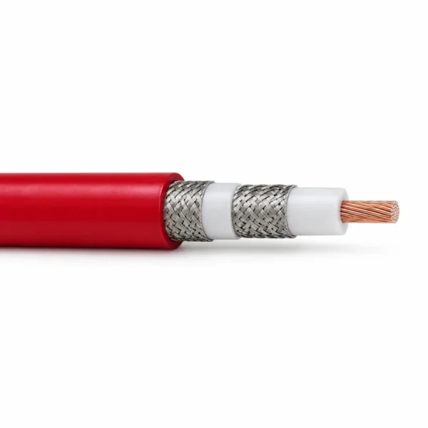
The representative construction image shows the compact 5 kV DC / 5 kV DC PE-X version. Use the reference configuration with the circuit diagram, voltage waveform, screen functions, cable length and termination requirements when requesting a quotation. TEBAOFLEX will align the cable build with the instrument or test-system interface and the available installation space.
Explore the high voltage DC and test cable range for related configurations.
For related single-shielded HV coaxial cables and ultra-high-voltage multi-conductor electron-beam cables, compare: High Voltage Coaxial Cable — PE-X, FEP and PE Configurations (for single-screened PE-X, FEP, and PE coaxial leads in general HV pulse and signal routing); X-Ray and Electron-Beam High Voltage Cable, 60–320 kV DC (for 60–320 kV DC multi-core filament, grid, and cathode assemblies in X-ray and electron-beam equipment). Confirm inner guard-to-core voltage, inter-braid insulation dielectric strength, and termination plug style before ordering.
Construction
The illustration represents the 0.50 mm², 5 kV DC / 5 kV DC PE-X/PUR configuration. Its one centre conductor is surrounded by two concentric braids separated by a second PE-X dielectric. The higher-voltage silicone and EPR designs have their own voltage-control and screen assemblies.

| Component | Material and construction |
|---|---|
| Centre conductor | One central copper conductor: stranded copper in the compact and silicone designs; solid 21.2 mm² copper in both 300 kV DC EPR configurations. |
| First insulation system | PE-X, silicone or EPR around the central conductor. Selected silicone and EPR constructions also include semiconductive conductor and insulation layers. |
| Inner conductive screen | Braid or a composite conductive screen around the first dielectric. The 35 mm² silicone construction uses a high-coverage spiral inner screen; the 300 kV designs use composite inner braid systems. |
| Second dielectric | A separate PE-X, PUR, silicone, polyester-tape or PE insulation system between the inner and outer conductive paths, as listed by configuration. |
| Outer conductive screen | A concentric copper braid in the compact designs and 300 kV SVA construction; two half-lapped copper-tape layers in the 300 kV SVG construction. |
| Separator and outer jacket | Nonwoven or polyester separators where specified, followed by red PUR, black silicone, red TPE-O or black PVC jacket. The jacket is not counted as a third electrical core. |
Applications
Use a triaxial construction when the equipment connection requires two distinct concentric conductive paths around the centre conductor. Match the assignment of each screen to the instrument circuit and the specified voltage across each insulation gap.
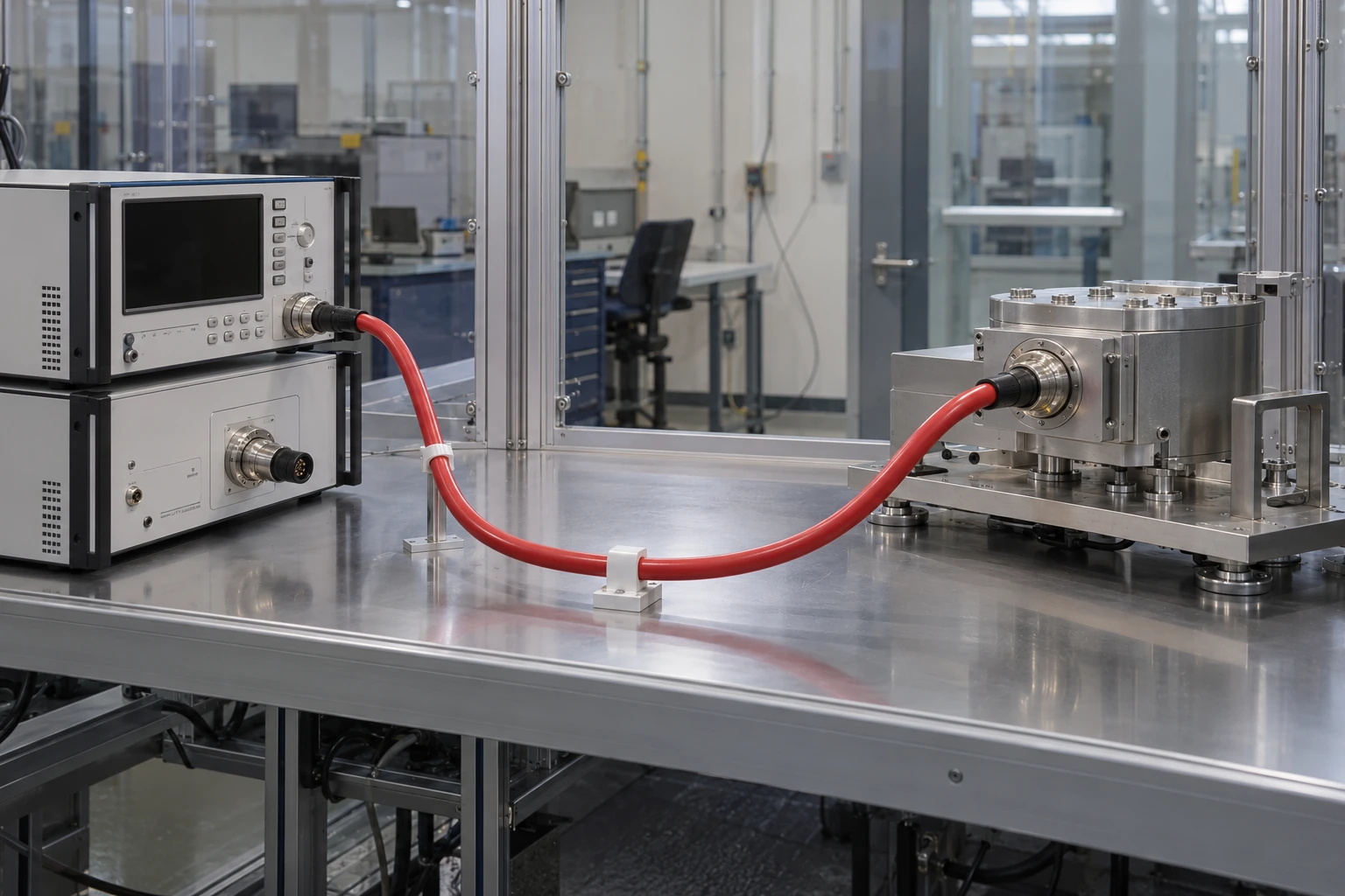
- Guarded high-voltage measurement connections using the compact 5 kV DC / 5 kV DC PE-X configuration.
- Low-noise instrument wiring using the 20 kV DC centre-to-inner-screen construction with its separate 500 V DC screen-to-screen rating.
- Silicone-dielectric test connections where the designated voltage path, low-temperature flexibility and bend radius suit the equipment arrangement.
- Fixed 300 kV DC test installations using the selected EPR configuration and matching high-voltage terminations.
- Separate centre, inner-screen and outer-screen functions are established by the equipment circuit; specify whether a screen acts as guard, return or shield.
- Provide the potential of every conductive path, waveform, frequency where relevant, termination geometry, screen current, bend space and environment with the enquiry.
For mobile cable-test-van field references and flexible single-screened silicone HV leads, see: High-Voltage Silicone Test Cable for a Cable Test Van — Lithuania (for a field deployment of flexible high-voltage test leads in a diagnostic cable test van); Shielded Silicone High Voltage Cable, 8–15 kV DC (for 8–15 kV DC single-braid shielded silicone cables where active guard cancellation is not required). Verify electrometer guard-circuit topology, flexing radius, and ambient temperature range before installation.
Specifications
| Parameter | Value |
|---|---|
| Cable arrangement | One centre conductor, two separately insulated concentric conductive screens. |
| Main dielectric options | PE-X, silicone or EPR, depending on the reference configuration. |
| Rated voltage by insulation path | Use the two voltage-path columns for every configuration; centre-to-inner-screen and inner-to-outer-screen duties are separate. |
| Centre conductor areas | 0.50, 0.75, 1.33, 21.2 or 35.0 mm², by construction. |
| Installation | Compact instrument connections or fixed high-voltage test routing, with configuration-specific bend radii. |
| Representative illustration | 5 kV DC / 5 kV DC PE-X/PUR design, 0.50 mm² centre conductor and 5.0 mm overall diameter. |
| Reference configuration | Centre to inner screen | Inner to outer screen | Main dielectric | Centre conductor (mm²) | Overall diameter (mm) |
|---|---|---|---|---|---|
| HSC-5-1X2SUA-2 0.50 mm² | 5 kV DC | 5 kV DC | PE-X | 0.50 | 5.0 ± 0.2 |
| HSC-15-1S2SUA-0 1.33 mm² | 15 kV AC | 1 kV AC | Silicone | 1.33 | 14.3 ± 0.5 |
| HSC-20-1X2SUA-2 0.50 mm² | 20 kV DC | 500 V DC | PE-X | 0.50 | 6.1 ± 0.15 |
| HSC-30-1S2SSB-0 0.75 mm² | 150 V | 30 kV DC | Silicone | 0.75 | 11.0 ± 0.5 |
| HSC-30-1S2STA-2 35.0 mm² | 30 kV DC | 5 kV DC | Silicone | 35.0 | 25.0 ± 0.9 |
| HSC-300-1E2SVA-0 21.2 mm² | 300 kV DC | Specify the screen-to-screen operating duty | EPR | 21.2 | 41.7 ± 0.8 |
| HSC-300-1E2SVG-0 21.2 mm² | 300 kV DC | 50 kV DC | EPR | 21.2 | 49.3 ± 0.8 |
| Reference configuration | Centre conductor | First dielectric and voltage-control layers | Inner screen | Second dielectric / separator | Outer screen and jacket |
|---|---|---|---|---|---|
| HSC-5-1X2SUA-2 0.50 mm² | Bare copper, 19 × AWG33; Ø 0.95 mm | PE-X to Ø 1.90 ± 0.05 mm | Tinned copper braid, 0.10 mm wires, 90% coverage; Ø 2.3 mm | PE-X to Ø 3.3 ± 0.2 mm | Tinned copper braid, 90% coverage, Ø 3.7 mm; nonwoven separator; red PUR jacket |
| HSC-15-1S2SUA-0 1.33 mm² | Tinned copper, 105 × 0.127 mm; Ø 1.53 mm | Semiconductive silicone to Ø 2.7 mm; silicone to Ø 8.5 mm; semiconductive PTFE tape to Ø 9.0 mm | Tinned copper braid, 6 × 24 × 0.15 mm, ≥85% coverage; Ø 9.6 mm | Polyester tape to Ø 9.7 mm; silicone to Ø 10.7 mm; polyester tape to Ø 10.8 mm | Tinned copper braid, 5 × 24 × 0.203 mm, ≥85% coverage, Ø 11.6 mm; nonwoven separator; black PUR jacket |
| HSC-20-1X2SUA-2 0.50 mm² | Tinned copper, 19 × AWG33; Ø 0.95 mm | PE-X to Ø 2.95 ± 0.05 mm; semiconductive tape | Tinned copper braid, 0.10 mm wires, 95% coverage; Ø 3.4 mm | PUR inner jacket to Ø 4.5 ± 0.15 mm | Tinned copper braid, 0.10 mm wires, 85% coverage, Ø 5.0 mm; red PUR jacket |
| HSC-30-1S2SSB-0 0.75 mm² | Tinned copper, 98 × 0.1 mm; Ø 1.2 mm | Silicone to Ø 2.5 mm | Tinned copper braid, 0.107 mm wires, ≥85% coverage; Ø 2.9 mm | Semiconductive tape and silicone to Ø 4.2 mm; white silicone to Ø 8.5 mm; semiconductive PTFE tape | Tinned copper braid, ≥85% coverage, Ø 9.4 mm; black silicone jacket |
| HSC-30-1S2STA-2 35.0 mm² | Tinned copper, 1117 × 0.203 mm; Ø 8.7 ± 0.44 mm | Semiconductive nonwoven tape; 0.7 mm semiconductive silicone; 3.0 mm white silicone | Z-lay tinned copper spiral screen, 36 × AWG18; 34.5 mm²; 98.7% optical coverage | PET foil; 1.0 mm white silicone second dielectric | Tinned copper braid, 10.8 mm², 80% coverage; nonwoven separator; red TPE-O jacket |
| HSC-300-1E2SVA-0 21.2 mm² | AWG4 solid copper; Ø 5.2 mm | Semiconductive EPR to Ø 6.6 mm; EPR to Ø 31.8 ± 0.6 mm; semiconductive EPR to Ø 33.0 mm | Two tinned copper braids: 9 × 24 × AWG30 and 11 × 24 × AWG30 | Two half-lapped layers of polyester tape | Tinned copper braid, AWG30, 85% coverage, Ø 36.6 mm; black PVC jacket |
| HSC-300-1E2SVG-0 21.2 mm² | AWG4 solid bare copper; Ø 5.2 mm | Semiconductive EPR to Ø 6.6 mm; EPR to Ø 31.8 ± 0.6 mm; 0.61 mm semiconductive EPR | Copper braid, 9 × 24 × AWG30, plus 45 × AWG20 copper wires | Half-lapped semiconductive tape; 2.54 mm LDHMW PE to Ø 41.2 mm; half-lapped semiconductive tape | Two half-lapped 0.05 mm copper-tape layers; black flame-retardant PVC jacket |
| Reference configuration | Min. bend radius: moving / fixed (mm) | Temperature condition (°C) | Mass (kg/m) |
|---|---|---|---|
| HSC-5-1X2SUA-2 0.50 mm² | 75 / 40 | Operating: −20 to +105 | Approx. 0.035 |
| HSC-15-1S2SUA-0 1.33 mm² | 210 / 105 | Operating: −40 to +90 | 0.330 |
| HSC-20-1X2SUA-2 0.50 mm² | 90 / 60 | Operating: −20 to +105 | Specify with the cable length enquiry |
| HSC-30-1S2SSB-0 0.75 mm² | 165 / 55 | Operating: −50 to +140 | 0.135 |
| HSC-30-1S2STA-2 35.0 mm² | Fixed installation: 188 | Operating: −50 to +105 | Specify with the cable length enquiry |
| HSC-300-1E2SVA-0 21.2 mm² | Fixed installation: 320 | Conductor temperature: −51 to +100 | Typical 2 |
| HSC-300-1E2SVG-0 21.2 mm² | Fixed installation: 356 | Maximum conductor temperature: +60 | Typical 2.4 |
| Reference configuration | Centre to inner screen test | Inner to outer screen test | Other test conditions |
|---|---|---|---|
| HSC-5-1X2SUA-2 0.50 mm² | 11 kV DC / 60 s | 11 kV DC / 60 s | Core spark test: 5 kV AC |
| HSC-15-1S2SUA-0 1.33 mm² | 40 kV DC / 1 min | 6 kV DC / 1 min | Jacket spark test: 5 kV AC; partial discharge ≤20 pC at UPD = 8 kV AC |
| HSC-20-1X2SUA-2 0.50 mm² | 41 kV DC / 60 s | 2 kV DC / 60 s | Core spark test: 15 kV AC |
| HSC-30-1S2SSB-0 0.75 mm² | Core-wire spark test: 3 kV AC | 61 kV DC / 1 min | Jacket spark test: 2.5 kV AC |
| HSC-30-1S2STA-2 35.0 mm² | 61 kV DC / 60 s routine; 48 kV DC / 24 h type test | 11 kV DC / 60 s routine; 8 kV DC / 24 h type test | Core spark test: 20 kV AC; inner / outer jacket spark tests: 5 / 5 kV AC |
| HSC-300-1E2SVA-0 21.2 mm² | 330 kV DC | 5 kV DC | Test voltages are distinct from screen-to-screen operating duty |
| HSC-300-1E2SVG-0 21.2 mm² | 330 kV DC | 55 kV DC | Screen-to-screen operating rating: 50 kV DC |
| Reference configuration | Electrical property | Value and path |
|---|---|---|
| HSC-5-1X2SUA-2 0.50 mm² | Impedance / capacitance | Centre–inner screen: typical 30 Ω / 165 pF/m; inner–outer screen: typical 15 Ω / 290 pF/m |
| HSC-5-1X2SUA-2 0.50 mm² | Resistance at 20°C | Centre conductor ≤41 Ω/km; centre–inner insulation ≥1 GΩ·km |
| HSC-15-1S2SUA-0 1.33 mm² | Capacitance | Centre–inner screen: typical 150 pF/m; inner–outer screen: typical 870 pF/m |
| HSC-15-1S2SUA-0 1.33 mm² | Resistance | Centre ≤14.6 Ω/km at 20°C; inner / outer braid <16 / <11 mΩ/m; inner–outer insulation >10⁹ Ω on 21 m cable length |
| HSC-20-1X2SUA-2 0.50 mm² | Centre–inner screen | Typical impedance 50 Ω; typical capacitance 102 pF/m; centre conductor resistance ≤40 Ω/km at 20°C |
| HSC-30-1S2SSB-0 0.75 mm² | Capacitance / resistance | Inner–outer capacitance typical 240 pF/m; centre resistance ≤24 Ω/km at 20°C; inner / outer braid resistance ≤35 / ≤11 Ω/km |
| HSC-300-1E2SVA-0 21.2 mm² | Centre–inner screen | Typical impedance 62 Ω; typical capacitance 100 pF/m; centre / inner braid resistance at 20°C: typical 0.86 / 1.3 mΩ/m |
| HSC-300-1E2SVG-0 21.2 mm² | Centre–inner screen | Typical impedance 62 Ω; typical capacitance 98 pF/m; centre / inner braid resistance at 20°C: typical 0.86 / 0.60 mΩ/m |
Reference codes identify the construction and electrical-path combination for the enquiry. They are read together with both voltage columns, the installation conditions and the termination drawing.
The 30 kV silicone HSC-30-1S2SSB-0 configuration carries its high-voltage duty between the screens; the central insulated wire has a separate 150 V rating.
The 300 kV SVA screen-to-screen value of 5 kV DC is an electrical test voltage. State the required operating potential between these screens in the enquiry.
For the 35 mm² silicone construction, the nominal inner-screen class is 35 mm² and the detailed screen build is 34.5 mm²; the outer braid is 10.8 mm².
Capacitance, impedance and resistance values identify their conductor paths. A 21 m sample insulation-resistance value is kept as a sample resistance, not converted to a length-normalised value.
Guard and shielding connections follow the instrument circuit. Match both insulation gaps and all terminations to the required potentials before installation.
Standards
| Standard or specification | Application |
|---|---|
| DIN EN 60332-2-2 | 20 s flame-test reference for the compact 5 kV DC / 5 kV DC and low-noise 20 kV DC PE-X constructions. |
| IEC 60332-1 | Flame-test reference for the 35 mm² silicone / TPE-O triaxial construction. |
| IEC 60754-1 / IEC 60754-2 | Halogen-acid-gas, acidity and conductivity test references for the 35 mm² silicone / TPE-O construction. |
| Configuration-specific DC withstand tests | Conductor-path test voltages and durations are listed in the electrical-test table; routine, type and spark tests remain separate. |
| Partial-discharge test condition | Silicone 15 kV AC construction: centre-to-inner-screen level ≤20 pC at UPD = 8 kV AC. |
Related cable options
Compare these cable options by service combination, movement, load, voltage and transmission requirement.

High Voltage Coaxial Cable — PE-X, FEP and PE Configurations
A related cable option for a different application or duty profile.
View product
Shielded Silicone High Voltage Cable, 8–15 kV DC
A related cable option for a different application or duty profile.
View product
High Voltage Silicone Wire, 3–60 kV DC
A related cable option for a different application or duty profile.
View productRequest a cable recommendation and quotation
Send the required services, cable length, mechanical duty, environment, termination and quantity. Our team will review the application before quoting.
- Include the product name or SKU plus the required cable length and quantity.
- Attach a specification, drawing or data sheet when available.