










Multicore High Voltage Cable, 10–60 kV DC
Multicore high voltage cable for fixed industrial test-system and OEM equipment connections. Reference configurations include silicone- or LDHMW PE-insulated cores, common-braid designs and an 8 + 1 central-earth construction, with model-specific ratings from 10 to 60 kV DC.
TEBAOFLEX multicore high voltage cable combines several separately insulated circuits in one cable for industrial high-voltage equipment and fixed test-system connections. This family covers reference constructions from 10 to 60 kV DC, with each voltage tied to the model and electrical path shown in the specification tables. Select the configuration by circuit count, conductor size, working potential, shielding and installation space.
Silicone-insulated, overall-braided versions include four equal cores in 2111, two larger and two smaller cores in 2181-1, three cores in 2183, five cores in 2188, and six cores in HSC-10-6SSSA. Model 2233 uses nineteen LDHMW PE-insulated cores with a common metallic screen. The HSC-30-9SSC-2 construction combines eight high-voltage wires with a central earth conductor and a silicone jacket, without an overall metallic screen.
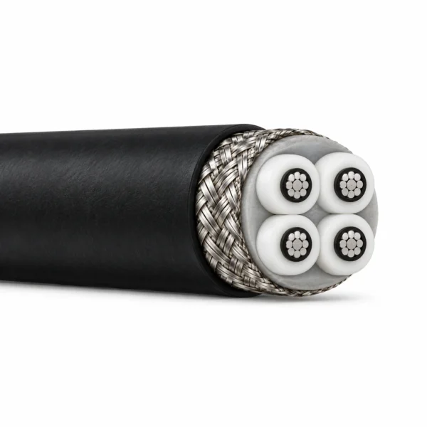
Silver-plated or tinned copper conductors, model-specific semiconductive layers, and neoprene, PVC or silicone jackets provide distinct options for equipment interfaces. The four-core 2111 construction is illustrated as the representative family design; the tables identify the different layouts and materials of the other reference models. Fixed and moving minimum bend radii are stated separately where available.
For selection, specify the potential of each circuit relative to the screen, earth and adjacent cores, together with operating temperature, routing and termination requirements. Browse the high-voltage DC and test cable range for other cable architectures. Our braided shield selection guide explains how screen construction affects cable selection.
The representative 2111 construction has four equal insulated cores in a near-square arrangement, one common tinned-copper braid and a black neoprene outer jacket. The model tables below distinguish common screens, semiconductive layers, fillers and earth conductors.

Silicone insulation with an overall braid
| Reference model | Conductor configuration and material | Individual-core construction | Assembly, screen and jacket |
|---|---|---|---|
| 2111 | 4 × AWG16. Silver-plated copper, 19 × 0.29 mm per conductor | Semiconducting silicone over each conductor; silicone dielectric; insulated core Ø 7.6 mm | Four equal cores in a near-square arrangement with filler; one common tinned-copper AWG34 braid, 80% coverage; black neoprene jacket |
| 2181-1 | 2 × AWG6 + 2 × AWG20. Tinned copper: AWG6, 133 × 0.36 mm; AWG20, 10 × 0.29 mm | Silicone insulation; insulated core Ø 7.6 mm (AWG6) and Ø 3.2 mm (AWG20) | Two larger and two smaller insulated cores; filler and binding tape; common tinned-copper AWG34 braid, 85% coverage, braid Ø 19.3 mm; grey PVC jacket |
| 2183 | 3 × AWG8. Tinned copper, 133 × 0.27 mm per conductor | Silicone dielectric; insulated core Ø 6.5 mm | Three cores with filler; common semiconductive tape; tinned-copper AWG34 braid, 85% coverage; black neoprene jacket |
| 2188 | 5 × AWG16. Silver-plated copper, 19 × 0.29 mm per conductor | Semiconducting silicone, silicone dielectric and an outer semiconductive ink layer; insulated core Ø 7.5 mm | Five cores around a Ø 5.3 mm neoprene centre cord; common semiconductive tape; tinned-copper AWG34 braid, 90% coverage; black PVC jacket |
| HSC-10-6SSSA | 6 × AWG20 (6 × 0.6 mm²). Tinned copper, 19 × 0.203 mm per conductor; conductor Ø < 0.99 mm | Semiconductive silicone Ø 2.2 mm; silicone dielectric Ø 3.6 mm | Six cores around a Ø 3.6 mm silicone/glass-fibre filler; laid-up assembly Ø 10.9 mm; polyester foil; common tinned-copper braid, 0.15 mm wires, ≥85% coverage, braid Ø 11.7 mm; silicone jacket |
LDHMW PE insulation with an overall braid
| Reference model | Conductor configuration and material | Individual-core construction | Assembly, screen and jacket |
|---|---|---|---|
| 2233 | 19 × AWG18. Tinned copper, 19 × 0.26 mm per conductor | Semiconductive PE and low-density high-molecular-weight polyethylene (LDHMW PE) dielectric; insulated core Ø 5.8 mm | Nineteen insulated cores; non-hygroscopic tape bedding; common tinned-copper AWG34 braid; PVC jacket |
Silicone 8 + 1 construction without an overall metallic screen
| Reference model | Conductor configuration and material | Individual-core construction | Assembly, screen and jacket |
|---|---|---|---|
| HSC-30-9SSC-2 | 8 × AWG22 HV + 1 × AWG12 earth. HV cores: tinned copper, 7 × AWG30, 0.36 mm² each, conductor Ø < 0.77 mm. Centre earth: tinned copper, 65 × AWG30, 3.3 mm², conductor Ø 2.4 mm | Eight white silicone-insulated HV cores Ø 4.2 mm around one green/yellow silicone-insulated centre earth Ø 6.8 mm | Eight HV cores around one earth core; laid-up assembly Ø 15.3 mm; tape; red silicone outer jacket; no common metallic braid |
HSC-10-6SSSA uses a non-conductive silicone/glass-fibre centre filler. HSC-30-9SSC-2 uses a central earth conductor. These are different constructions.
Use this family for multiple high-voltage circuits routed between industrial test equipment, measurement enclosures and OEM equipment modules. The common-braid configurations provide an overall screen around the insulated core assembly; the 8 + 1 construction provides a separate central earth connection.

- Fixed multichannel connections in high-voltage test and measurement systems.
- Internal or inter-enclosure wiring requiring several separately insulated circuits in one cable route.
- Equipment designs requiring a model-specific combination of conductor size, silicone or PE dielectric, and overall shielding.
Choose the required electrical potential path before comparing voltage ratings. For HSC-30-9SSC-2, specify the potential between the eight high-voltage circuits and the central earth in the enquiry; its core–core test value is listed separately from the nominal high-voltage-wire rating. Apply the stated minimum bend radius and provide routing, support, termination and movement requirements for the selected configuration.
Dimensions and weights are reference values for the listed constructions. D denotes the finished cable outside diameter. Voltage values below retain the stated electrical path; AC test values are listed separately from DC working ratings.
Silicone insulation with an overall braid
| Reference model / configuration | Voltage and electrical path | Overall diameter | Minimum bend radius | Operating temperature | Weight |
|---|---|---|---|---|---|
| 2111 — 4 × AWG16 | 50 kV DC, conductor–shield | 24.1 mm | 102 mm, static | −51 to +60°C | 0.21 kg/m |
| 2181-1 — 2 × AWG6 + 2 × AWG20 | 15 kV DC, conductor–shield | 20.3 mm | 152 mm, static | −51 to +60°C | 0.60 kg/m |
| 2183 — 3 × AWG8 | 15 kV DC, conductor–braid | 18.5 mm | 101 mm, static | −51 to +60°C | 0.37 kg/m |
| 2188 — 5 × AWG16 | 50 kV DC, conductor–shield | 24.6 mm | 127 mm, static | −51 to +60°C | 0.45 kg/m |
| HSC-10-6SSSA — 6 × AWG20 (6 × 0.6 mm²) | 10 kV DC, conductor–braid | 14.1 ± 0.7 mm | 7.5 × D, fixed; 15 × D, moving | −50 to +90°C | 250 kg/km total; 83 kg/km copper |
LDHMW PE insulation with an overall braid
| Reference model / configuration | Voltage and electrical path | Overall diameter | Minimum bend radius | Operating temperature | Weight |
|---|---|---|---|---|---|
| 2233 — 19 × AWG18 | 60 kV DC, conductor–shield | 30.5 mm | 482 mm, static | −51 to +60°C | 0.67 kg/m |
Silicone 8 + 1 construction without an overall metallic screen
| Reference model / configuration | Voltage and electrical path | Overall diameter | Minimum bend radius | Operating temperature | Weight |
|---|---|---|---|---|---|
| HSC-30-9SSC-2 — 8 × AWG22 HV + 1 × AWG12 earth | 30 kV DC nominal HV-wire rating | 19.1 ± 0.7 mm | 150 mm, fixed; 300 mm, moving | −50 to +150°C | Total weight on request; copper 0.059 kg/m |
Additional electrical data and test conditions
| Reference model | Parameter | Value / condition |
|---|---|---|
| 2111 | Impedance | 44 Ω |
| 2111 | Capacitance | 164 pF/m |
| HSC-10-6SSSA | Conductor resistance at 20°C | < 32.4 Ω/km |
| HSC-10-6SSSA | Spark test | 25 kV DC or 10 kV AC |
| HSC-10-6SSSA | Conductor–conductor test | 20 kV DC or 8 kV AC, 1 minute |
| HSC-10-6SSSA | Conductor–braid test | 15 kV DC or 6 kV AC, 1 minute |
| HSC-30-9SSC-2 | HV-core resistance at 20°C | ≤ 54.8 Ω/km |
| HSC-30-9SSC-2 | Centre-earth resistance at 20°C | ≤ 5.9 Ω/km |
| HSC-30-9SSC-2 | Individual-core spark test | 20 kV AC |
| HSC-30-9SSC-2 | Core–core test | 5 kV AC |
The 30 kV DC value for HSC-30-9SSC-2 identifies the nominal rating of its individual high-voltage wires. The assembly uses a separate 5 kV AC core–core test condition.
Construction and electrical values are specified by reference model. Agree the applicable working potentials, test paths, test duration and acceptance requirements for the ordered cable.
| Item | Specification basis |
|---|---|
| Conductor and dielectric | Model-specific conductor plating, stranding, semiconductive layers and dielectric materials as listed in Construction. |
| Working and test voltages | DC ratings retain their stated electrical paths. Separate AC/DC test conditions are listed for HSC-10-6SSSA and HSC-30-9SSC-2. |
| Installation | Static, fixed and moving bend-radius conditions apply to the corresponding reference model. |
For general high-voltage test terminology and scope, consult IEC 60060-1:2025 — High-voltage test techniques when defining the project test specification.
Related cable options
Compare these cable options by service combination, movement, load, voltage and transmission requirement.
X-Ray and Electron-Beam High Voltage Cable, 60–320 kV DC
A related cable option for a different application or duty profile.
View product
High Voltage Coaxial Cable — PE-X, FEP and PE Configurations
A related cable option for a different application or duty profile.
View product
Shielded Silicone High Voltage Cable, 8–15 kV DC
A related cable option for a different application or duty profile.
View productRequest a cable recommendation and quotation
Send the required services, cable length, mechanical duty, environment, termination and quantity. Our team will review the application before quoting.
- Include the product name or SKU plus the required cable length and quantity.
- Attach a specification, drawing or data sheet when available.