

(N)3GHSSYCY Medium-Voltage Mining & Tunnelling Cable
(N)3GHSSYCY cable is a flexible medium-voltage feeder cable for mobile or shiftable equipment and stationary transformer connections in mining, tunnelling and underground excavation projects.
- Rated voltage: 3.6/6 kV, 6/10 kV, 8.7/15 kV, 12/20 kV and 18/30 kV
- Power conductors: flexible Class 5 electrolytic copper
- Insulation: 3GI3 EPR with semiconductive field-control layers
- Auxiliary elements: pilot/control cores, protective conductors and an overall monitoring conductor
- Mechanical protection: galvanized steel-wire braid with a PVC sheath system
- Temperature range: -40°C to +90°C fixed; +5°C to +90°C in mobile service
- Selection basis: confirm voltage, core arrangement, movement duty, route geometry and project documentation before ordering
For a technical quotation, send the voltage, conductor size, cable length, equipment, movement pattern and required inspection documents.
(N)3GHSSYCY Cable for Underground Medium-Voltage Power
(N)3GHSSYCY cable is intended for medium-voltage power connections where a mining or tunnelling route requires flexible conductors, screened power cores, auxiliary supervision conductors and steel-braid mechanical protection in one cable. Typical duties include power supply to mobile or shiftable underground equipment and stationary connections to transformers or distribution equipment.
The model name alone is not enough to approve a substitute. The voltage class, phase-conductor size, protective-conductor arrangement, pilot/control cores, monitoring circuit and cable diameter must match the equipment, protection scheme and installation interfaces for the intended underground service. Route design also matters: pulling tension, torsion, direction changes, ambient temperature and movement frequency should be checked together rather than treated as separate catalogue values.
- Suitable for: engineered mining and tunnelling MV feeder connections.
- Confirm first: voltage, cross-section, conductor arrangement and termination interface.
- Review the route: fixed, shiftable or mobile duty; rollers, bends and direction changes.
- Require evidence for: project approvals, certificates, environmental resistance or continuous-reeling duty.
Browse the mining and tunnelling cable range when the equipment needs a different movement pattern, sheath system or grounding arrangement.
(N)3GHSSYCY Cable Construction
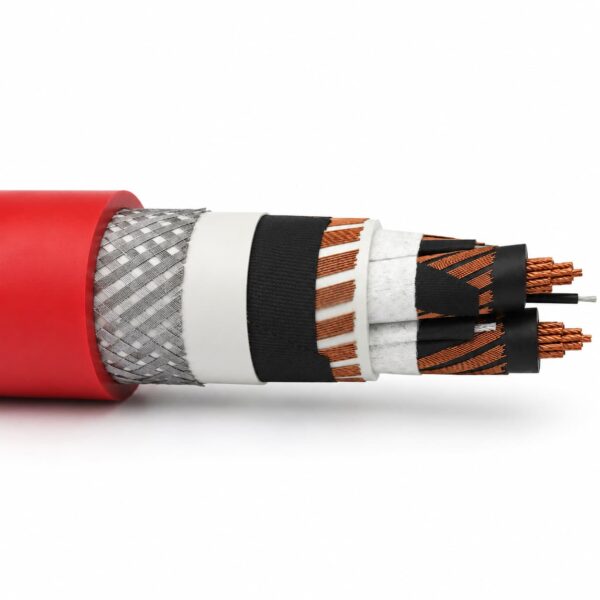
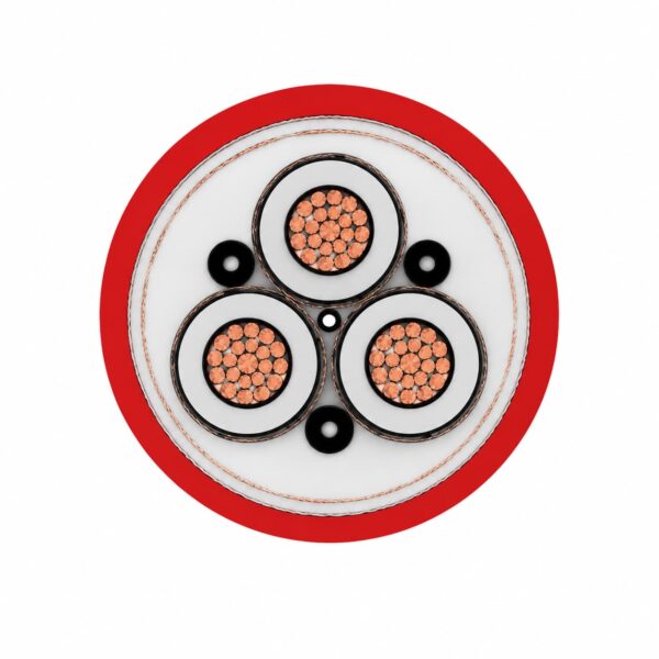
The supplied construction combines three medium-voltage power cores with pilot/control and protective conductors, an overall monitoring element, intermediate sheathing and galvanized steel-wire braid. Each layer must be checked against the termination and monitoring design for the project.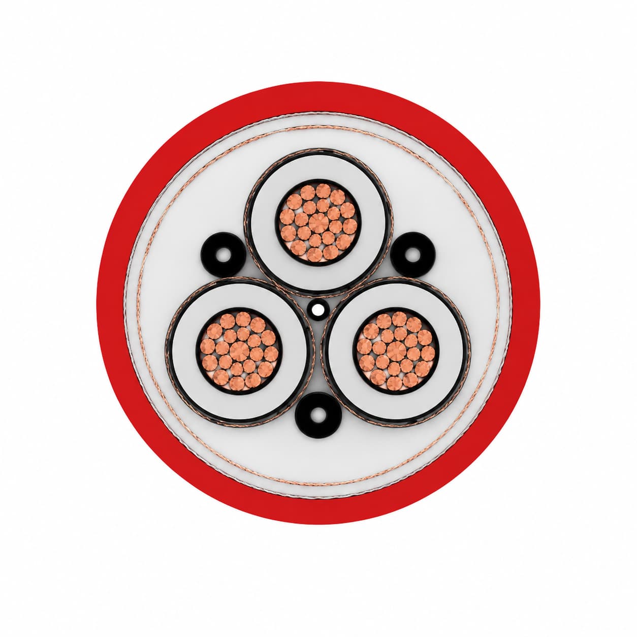
| Layer or element | Supplied construction | Selection significance |
|---|---|---|
| Power conductor | Flexible electrolytic copper, Class 5 according to DIN VDE 0295 | Supports installation and equipment movement within the stated mechanical limits. |
| Power-core insulation | 3GI3 EPR compound | Forms the primary medium-voltage insulation system. |
| Electrical field control | Extruded semiconductive rubber layers; the supplied 3.6/6 kV description uses an outer semiconductive layer only | The field-control and termination system must match the selected voltage class. |
| Protective conductor | Plain copper wires or copper-wire braid laid concentrically around each main core | Confirm the protective-conductor cross-section and bonding method. |
| Pilot/control cores | 3GI3 EPR insulated; black and number coded | Confirm quantity, identification and interface with the equipment control circuit. |
| Core assembly | Three main conductors with three pilot/control cores in the outer interstices | Check the ordered core designation rather than relying only on the model name. |
| Inner sheath | YM5 PVC compound | Provides a bedding layer around the laid-up core assembly. |
| Monitoring conductor | Semiconductive tape with overall concentric copper wires and synthetic tape | Its protective function depends on the connected monitoring system and circuit design. |
| Intermediate sheath | DMV6 PVC compound | Separates the monitoring assembly from the braid system. |
| Armour / reinforcement | Galvanized steel-wire braid, minimum 75% coverage | Adds mechanical reinforcement; it does not by itself establish suitability for every dragging or reeling duty. |
| Outer sheath | DMV6 PVC compound, red or black | Confirm colour, marking and environmental requirements at quotation stage. |
Applications and Duty Boundaries
(N)3GHSSYCY cable is used as a flexible medium-voltage power connection for mining and tunnelling equipment. The cable should be selected as part of the complete power, protection, monitoring and routing system.Typical applications
- Medium-voltage supply to mobile or shiftable equipment in underground mines and excavations
- Tunnelling power routes between distribution equipment, transformers and operating machinery
- Stationary transformer or feeder connections where the screened-core and monitoring arrangement is required
- Routes that need flexible Class 5 conductors together with steel-braid mechanical reinforcement
Selection boundaries
- Movement: state whether the cable is fixed, occasionally repositioned, shiftable, trailing or continuously reeled. Continuous-reeling suitability is not established by the model name alone.
- Protection scheme: verify the earth, pilot/control and monitoring circuits against the equipment wiring and relay logic.
- Route: provide bend points, rollers, direction changes, pulling method, expected torsion and cable support arrangement.
- Environment: request separate evidence for submersion, oil, chemicals, UV, flame performance or hazardous-area approval when the project requires it.
- Replacement: do not cross-reference another manufacturer solely by conductor size and voltage; compare the full construction and nominal diameter.
(N)3GHSSYCY Cable Specifications
The values below are taken from the current TEBAOFLEX product data sheet. They are selection inputs, not a substitute for the final cable schedule, termination design or project ampacity calculation.| Rated voltage Uo/U | AC test voltage | Maximum operating voltage AC | Maximum operating voltage DC |
|---|---|---|---|
| 3.6/6 kV | 11 kV | 4.2/7.2 kV | 5.4/10.8 kV |
| 6/10 kV | 17 kV | 6.9/12 kV | 9/18 kV |
| 8.7/15 kV | 24 kV | 10.4/18 kV | 13.5/27 kV |
| 12/20 kV | 29 kV | 13.9/24 kV | 18/36 kV |
| 18/30 kV | 43 kV | 20.8/36 kV | 27/54 kV |
Operating and Mechanical Limits
| Fixed installation temperature | -40°C to +90°C |
|---|---|
| Mobile-service temperature | +5°C to +90°C |
| Maximum tensile load | 20 N/mm² |
| Maximum torsion | 25°/m |
| Maximum stated travel speed | 30 m/min |
| Minimum distance for a direction change | 12 × D, where D is the cable overall diameter |
| Minimum bending radius | Determine for the installation mode according to DIN VDE 0298-3 and the final product drawing |
| Current-carrying capacity | Determine for the installation conditions according to DIN VDE 0298-4 |
Nominal Size Schedule Summary
Dimensions and weights are nominal catalogue values and can vary with the ordered construction and manufacturing tolerance. Confirm the final data sheet before approving glands, rollers, drums or terminations.| Voltage class | Phase-conductor range listed | Nominal overall-diameter span | Approximate weight span |
|---|---|---|---|
| 3.6/6 kV | 25-185 mm² | 47.0-74.0 mm | 3,600-11,300 kg/km |
| 6/10 kV | 25-185 mm² | 54.0-79.2 mm | 4,200-12,400 kg/km |
| 8.7/15 kV | 25-95 mm² | 54.2-69.0 mm | 4,530-9,120 kg/km |
| 12/20 kV | 25-185 mm² | 54.4-82.0 mm | 4,920-11,870 kg/km |
| 18/30 kV | Voltage rating is listed in the supplied data sheet; a dimensional schedule was not supplied. Confirm the required size and construction. | ||
Standards, Test References and Documentation
| Reference | |
|---|---|
| DIN VDE 0250-605 | |
| DIN VDE 0250-1 | |
| DIN VDE 0295 / Class 5 | |
| DIN VDE 0298-3 and -4 | |
| DIN VDE 0472-501, -503 and -508 | |
| DIN VDE 0472-401, -402, -602, -303 and -615 | |
| VDE 0482-332-1-2 / DIN EN 60332-1-2 / IEC 60332-1 | |
| IEC 60502-2 |
Related cable options
Compare these cable options by service combination, movement, load, voltage and transmission requirement.
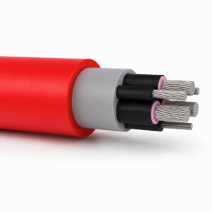
(N)TSCGEWÖU Cable 3.6/6kV to 12/20kV Mine Distribution Cable
A related cable option for a different application or duty profile.
View product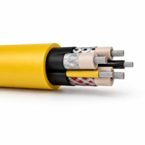
(N)TMCETMPU Cable 6/10 kV to 14/25 kV Portable Mining Trailing Cable
A related cable option for a different application or duty profile.
View productRequest a cable recommendation and quotation
Send the required services, cable length, mechanical duty, environment, termination and quantity. Our team will review the application before quoting.
- Include the product name or SKU plus the required cable length and quantity.
- Attach a specification, drawing or data sheet when available.