








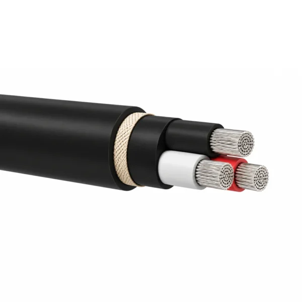
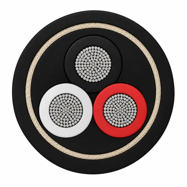




PNCT Torsion Cable 600 V – 2PNCT-T / 3PNCT-T / TOR-2PNCT
600 V EPR-insulated, chloroprene-sheathed cables for torsion duty. Compare single-sheath 2PNCT-T, cloth-reinforced 3PNCT-T and individually taped TOR-2PNCT for the required moving connection.
PNCT torsion cable is a 600 V rubber cable for moving connections that experience twisting. The 2PNCT-T, 3PNCT-T and TOR-2PNCT constructions use EPR insulation and a chloroprene sheath, with an 80°C maximum conductor temperature. Their core assembly and reinforcement suit different crane and industrial equipment routes.
Choose 2PNCT-T for torsion applications such as coiled-curtain cable systems. Choose 3PNCT-T when the route calls for the reinforced construction: a chloroprene inner sheath, cloth reinforcement and a chloroprene outer sheath. TOR-2PNCT is designed for the twisting connection of a rotating crane; tape around the individual cores helps them slide against one another during movement.
The three specification tables keep each construction together. They include core configuration, diameter, weight and electrical resistance. The 2PNCT-T and 3PNCT-T tables also give permissible tensile load, while the TOR-2PNCT table gives its configuration-specific minimum bend radius. Use these values with the actual support arrangement, available loop space and termination dimensions.
Provide the selected model, conductor area, core count and cable length with the enquiry. For the moving section, include the rotation angle, free twisting length, travel sequence and expected duty. TEBAOFLEX can quote the cable against that installation brief. For a route dominated by vertical winding or conventional mobile service, compare the related reeling and general-purpose PNCT cable options.
Explore the port and festoon cable range for related configurations.
When comparing 600 V PNCT torsion cables (2PNCT-T, 3PNCT-T, TOR-2PNCT) against PUR anti-torsion reeling cables or standard plane-bending PNCT, evaluate these options: TRA Anti-Torsion PUR Reeling Cable 0.6/1 kV (0.6/1 kV polyurethane-sheathed anti-torsion reeling cable for high-abrasion European-style crane drums and wind turbines); PNCT Reeling Cable 600 V–1 kV — Round, Flat and Reinforced Types (600 V–1 kV round, flat, and reinforced PNCT reeling cables designed for single-plane drum winding and festoons). Specify torsion-rated stranding and anti-twist braid whenever the cable twists around its longitudinal axis.
Construction
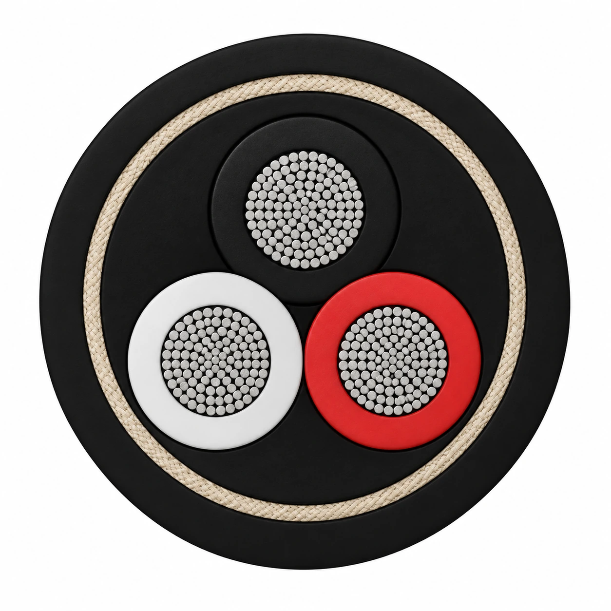
Each model has its own torsion construction. The illustration represents 3PNCT-T 3×38 mm², with three equal cores in a triangular arrangement, an inner sheath, cloth reinforcement and an outer sheath.
| Component | Material and construction |
|---|---|
| 2PNCT-T / 3PNCT-T conductors | Flexible tinned annealed copper. |
| Insulation | EPR rubber around the phase or control conductors. |
| 2PNCT-T core assembly | Insulated cores assembled beneath a binding tape and black chloroprene sheath. |
| 3PNCT-T reinforcement | Black chloroprene inner sheath, cloth reinforcement and black chloroprene outer sheath. |
| TOR-2PNCT core assembly | Stranded conductors with separator and EPR insulation; individual core tape wraps promote sliding between cores. Fillers and a binder support the bundle beneath the chloroprene sheath. |
| Core identification | 2PNCT-T / 3PNCT-T: black for one core; black and white for two; black, white and red for three; black, white, red and green for four; tracer identification from five cores. TOR-2PNCT uses colour and tracer identification. |
Applications
Select the model for the twisting motion and support geometry of the equipment. Keep the free cable length and bend radius compatible with the complete movement cycle.

- 2PNCT-T for coiled-curtain torsion connections on industrial cranes and handling equipment.
- 3PNCT-T for torsion routes requiring an inner sheath and cloth-reinforced outer construction.
- TOR-2PNCT for the twisting section between fixed and moving parts of rotating cranes.
- Industrial equipment connections with a defined rotation range, supported cable route and suitable termination arrangement.
For crane drum engineering guidelines and vertical high-tension reeling alternatives, consult these technical resources: Reeling Cable Solutions for Cranes and Mobile Equipment (application engineering for level-wind, monospiral, and random-wind crane cable reels); 600V RE(V)-2PNCT-RF Vertical Reeling Rubber Cable (600 V aramid-reinforced vertical reeling rubber cable for crane spreader drops and deep-shaft hoists). Verify maximum degrees of twist per meter and vertical suspension tensile load.
Specifications
| Parameter | Value |
|---|---|
| Rated voltage | 600 V |
| AC test voltage | 3000 V for 1 minute |
| Maximum conductor temperature | 80°C |
| 2PNCT-T / 3PNCT-T operating temperature | −15 to +80°C |
| 2PNCT-T / 3PNCT-T minimum bend radius | 7.5 × cable outside diameter |
| 2PNCT-T / 3PNCT-T permissible sidewall pressure | 4900 N/m |
| 2PNCT-T / 3PNCT-T permissible tensile load | Configuration-specific values in the tables |
| TOR-2PNCT minimum bend radius | 110–230 mm, as specified for each configuration |
| Insulation | EPR rubber |
| Sheath | Chloroprene rubber; black for 2PNCT-T and 3PNCT-T |
| 3PNCT-T reinforcement | Cloth layer between inner and outer chloroprene sheaths |
| Model and configuration (mm²) | Conductor OD (mm) | Nominal cable OD (mm) | Max. cable OD (mm) | Approx. weight (kg/km) | Max. conductor resistance (Ω/km) | Permissible tensile load (N) |
|---|---|---|---|---|---|---|
| 2PNCT-T 1×38 | 9.1 | 15.4 | 17.4 | 525 | 0.525 | 1110 |
| 2PNCT-T 1×60 | 11.6 | 18.9 | 20.9 | 800 | 0.329 | 1760 |
| 2PNCT-T 1×100 | 15.2 | 23.7 | 26.1 | 1310 | 0.193 | 2940 |
| 2PNCT-T 1×150 | 18.7 | 27.5 | 30.3 | 1790 | 0.136 | 4410 |
| 2PNCT-T 1×200 | 21.2 | 31.4 | 34.5 | 2410 | 0.0993 | 5880 |
| 2PNCT-T 2×2 | 1.8 | 10.2 | 12.2 | 150 | 10.2 | 110 |
| 2PNCT-T 2×3.5 | 2.5 | 11.5 | 13.5 | 205 | 5.54 | 200 |
| 2PNCT-T 3×2 | 1.8 | 10.7 | 12.7 | 175 | 10.2 | 170 |
| 2PNCT-T 3×3.5 | 2.5 | 12.3 | 14.3 | 250 | 5.54 | 300 |
| 2PNCT-T 3×5.5 | 3.1 | 14.6 | 16.6 | 365 | 3.56 | 480 |
| 2PNCT-T 3×8 | 3.7 | 16.1 | 18.1 | 465 | 2.52 | 700 |
| 2PNCT-T 3×14 | 4.9 | 19.4 | 21.4 | 665 | 1.43 | 1230 |
| 2PNCT-T 3×22 | 7.0 | 25.6 | 28.2 | 1100 | 0.919 | 1940 |
| 2PNCT-T 3×38 | 9.1 | 30.7 | 33.8 | 1700 | 0.541 | 3350 |
| 2PNCT-T 4×2 | 1.8 | 11.6 | 13.6 | 210 | 10.2 | 230 |
| 2PNCT-T 4×3.5 | 2.5 | 13.6 | 15.6 | 315 | 5.54 | 410 |
| 2PNCT-T 4×5.5 | 3.1 | 16.1 | 18.1 | 455 | 3.56 | 640 |
| 2PNCT-T 6×2 | 1.8 | 14.0 | 16.0 | 310 | 10.2 | 350 |
| 2PNCT-T 6×3.5 | 2.5 | 16.2 | 18.2 | 450 | 5.54 | 610 |
| 2PNCT-T 6×5.5 | 3.1 | 19.5 | 21.5 | 670 | 3.56 | 970 |
| 2PNCT-T 6×8 | 3.7 | 21.5 | 23.7 | 870 | 2.52 | 1410 |
| 2PNCT-T 6×14 | 4.9 | 26.0 | 28.6 | 1220 | 1.43 | 2460 |
| 2PNCT-T 8×2 | 1.8 | 16.4 | 18.4 | 415 | 10.2 | 470 |
| 2PNCT-T 8×3.5 | 2.5 | 19.1 | 21.1 | 620 | 5.54 | 820 |
| 2PNCT-T 12×2 | 1.8 | 19.2 | 21.2 | 510 | 10.2 | 700 |
| 2PNCT-T 12×3.5 | 2.5 | 22.3 | 24.5 | 765 | 5.54 | 1230 |
| 2PNCT-T 16×2 | 1.8 | 21.4 | 23.5 | 640 | 10.2 | 940 |
| 2PNCT-T 16×3.5 | 2.5 | 24.7 | 27.2 | 965 | 5.54 | 1640 |
| 2PNCT-T 20×2 | 1.8 | 23.8 | 26.2 | 800 | 10.2 | 1170 |
| 2PNCT-T 20×3.5 | 2.5 | 27.6 | 30.4 | 1210 | 5.54 | 2050 |
| 2PNCT-T 24×2 | 1.8 | 26.2 | 28.8 | 955 | 10.2 | 1410 |
| 2PNCT-T 24×3.5 | 2.5 | 30.7 | 33.8 | 1460 | 5.54 | 2460 |
| 2PNCT-T 30×2 | 1.8 | 28.0 | 30.8 | 1130 | 10.2 | 1760 |
| 2PNCT-T 30×3.5 | 2.5 | 32.7 | 36.0 | 1740 | 5.54 | 3080 |
| Model and configuration (mm²) | Conductor OD (mm) | Nominal cable OD (mm) | Max. cable OD (mm) | Approx. weight (kg/km) | Max. conductor resistance (Ω/km) | Permissible tensile load (N) |
|---|---|---|---|---|---|---|
| 3PNCT-T 1×38 | 9.1 | 18.9 | 20.9 | 635 | 0.525 | 1110 |
| 3PNCT-T 1×60 | 11.6 | 22.8 | 25.1 | 945 | 0.329 | 1760 |
| 3PNCT-T 1×100 | 15.2 | 26.8 | 29.5 | 1440 | 0.193 | 2940 |
| 3PNCT-T 1×150 | 18.7 | 32.8 | 36.1 | 2060 | 0.136 | 4410 |
| 3PNCT-T 1×200 | 21.2 | 36.9 | 40.6 | 2730 | 0.0993 | 5880 |
| 3PNCT-T 2×2 | 1.8 | 14.6 | 16.6 | 255 | 10.2 | 110 |
| 3PNCT-T 2×3.5 | 2.5 | 15.9 | 17.9 | 315 | 5.54 | 200 |
| 3PNCT-T 3×2 | 1.8 | 15.3 | 17.3 | 285 | 10.2 | 170 |
| 3PNCT-T 3×3.5 | 2.5 | 16.8 | 18.8 | 375 | 5.54 | 300 |
| 3PNCT-T 3×5.5 | 3.1 | 18.3 | 20.3 | 470 | 3.56 | 480 |
| 3PNCT-T 3×8 | 3.7 | 19.7 | 21.7 | 580 | 2.52 | 700 |
| 3PNCT-T 3×14 | 4.9 | 23.5 | 25.9 | 860 | 1.43 | 1230 |
| 3PNCT-T 3×22 | 7.0 | 30.8 | 33.9 | 1450 | 0.919 | 1940 |
| 3PNCT-T 3×38 | 9.1 | 36.0 | 39.6 | 2130 | 0.541 | 3350 |
| 3PNCT-T 4×2 | 1.8 | 16.6 | 18.6 | 345 | 10.2 | 230 |
| 3PNCT-T 4×3.5 | 2.5 | 18.3 | 20.3 | 455 | 5.54 | 410 |
| 3PNCT-T 4×5.5 | 3.1 | 19.9 | 21.9 | 580 | 3.56 | 640 |
| Model and configuration (mm²) | Stranding (No./mm) | Conductor OD (mm) | Insulation (mm) | Sheath (mm) | Approx. cable OD (mm) | Approx. weight (kg/km) | Max. resistance at 20°C (Ω/km) | Min. insulation resistance at 20°C (MΩ·km) | Min. bend radius (mm) |
|---|---|---|---|---|---|---|---|---|---|
| TOR-2PNCT 3×8 | 50/0.45 | 3.7 | 1.0 | 2.1 | 17.0 | 475 | 2.52 | 400 | 110 |
| TOR-2PNCT 3×14 | 88/0.45 | 4.9 | 1.0 | 2.3 | 20 | 725 | 1.43 | 300 | 120 |
| TOR-2PNCT 3×22 | 7/20/0.45 | 7.0 | 1.2 | 2.7 | 26 | 1170 | 0.919 | 300 | 160 |
| TOR-2PNCT 3×30 | 7/27/0.45 | 8.1 | 1.2 | 2.8 | 28 | 1460 | 0.681 | 300 | 170 |
| TOR-2PNCT 3×38 | 7/34/0.45 | 9.1 | 1.2 | 3.0 | 31 | 1780 | 0.541 | 200 | 190 |
| TOR-2PNCT 3×60 | 19/20/0.45 | 11.6 | 1.5 | 3.4 | 38 | 2780 | 0.339 | 200 | 230 |
| TOR-2PNCT 4×38 | 7/34/0.45 | 9.1 | 1.2 | 3.2 | 34 | 2280 | 0.541 | 200 | 210 |
| TOR-2PNCT 6×3.5 | 45/0.32 | 2.5 | 0.8 | 2.1 | 17.0 | 460 | 5.54 | 400 | 110 |
| TOR-2PNCT 6×8 | 50/0.45 | 3.7 | 1.0 | 2.4 | 22 | 875 | 2.52 | 400 | 140 |
| TOR-2PNCT 10×3.5 | 45/0.32 | 2.5 | 0.8 | 2.5 | 24 | 770 | 5.54 | 400 | 150 |
| TOR-2PNCT 12×3.5 | 45/0.32 | 2.5 | 0.8 | 2.6 | 24 | 875 | 5.54 | 400 | 150 |
| TOR-2PNCT 16×3.5 | 45/0.32 | 2.5 | 0.8 | 2.7 | 27 | 1110 | 5.54 | 400 | 170 |
| TOR-2PNCT 20×3.5 | 45/0.32 | 2.5 | 0.8 | 2.9 | 30 | 1380 | 5.54 | 400 | 180 |
| TOR-2PNCT 24×3.5 | 45/0.32 | 2.5 | 0.8 | 3.1 | 33 | 1660 | 5.54 | 400 | 200 |
| TOR-2PNCT 30×3.5 | 45/0.32 | 2.5 | 0.8 | 3.2 | 35 | 1990 | 5.54 | 400 | 210 |
Dimensions and weights apply to the model and configuration shown. Nominal and maximum diameters are separate columns for 2PNCT-T and 3PNCT-T.
For 2PNCT-T and 3PNCT-T, calculate the 7.5D bend radius from the selected cable outside diameter. For TOR-2PNCT, use the stated minimum radius in its own table.
Specify rotation angle, free cable length, number of movement cycles and support arrangement when selecting the torsion connection.
Select conductor size for the circuit load, installation temperature and grouping. The dimensional tables are configuration data.
Standards
| Standard or specification | Application |
|---|---|
| JIS C 3327 | Rubber cabtyre cable construction reference for the PNCT family; the selected torsion design adds its model-specific assembly. |
| AC dielectric test | 3000 V for 1 minute. |
| Torsion construction | 2PNCT-T, cloth-reinforced 3PNCT-T and individually taped TOR-2PNCT are specified separately. |
Related cable options
Compare these cable options by service combination, movement, load, voltage and transmission requirement.
600V 2PNCT Flexible Rubber Cable (JIS C 3327)
A related cable option for a different application or duty profile.
View product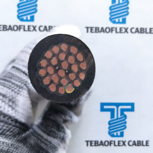
600V RE(V)-2PNCT-RF Vertical Reeling Rubber Cable
A related cable option for a different application or duty profile.
View product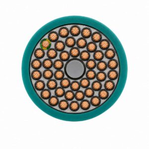
TRA Anti-Torsion PUR Reeling Cable 0.6/1 kV
A related cable option for a different application or duty profile.
View productRequest a cable recommendation and quotation
Send the required services, cable length, mechanical duty, environment, termination and quantity. Our team will review the application before quoting.
- Include the product name or SKU plus the required cable length and quantity.
- Attach a specification, drawing or data sheet when available.