








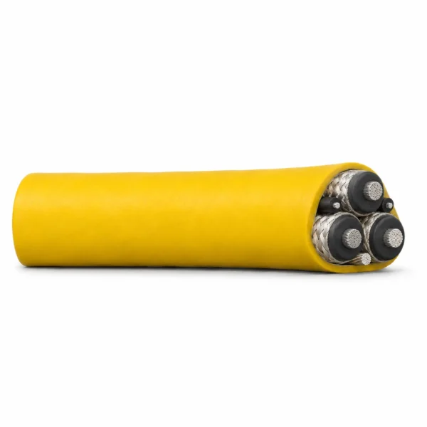
Trackless Scoop 640/1100 V Mining Cable
Trackless Scoop 640/1100 V cable uses EPR insulation and individual tinned-copper/nylon phase screens. Select the listed yellow CM configurations or the separate 35 mm² reflective TPU construction. Pilot and earth sizes are configuration-specific. MOQ: 50 m; lead time: 7–45 working days.
Trackless Scoop mining cable is a 640/1100 V flexible supply cable for loaders, drilling equipment and other mine machinery. Its construction uses three individually screened EPR power cores with a separate tinned-copper earth conductor. The 10–70 mm² power configurations also contain two unscreened pilot cores; the listed 2.5 mm² configuration has no pilots. Keep this distinction on the connection schedule when specifying a replacement.
The yellow CM version uses an extra-heavy-duty rubber sheath around the laid-up assembly. A separate reflective version combines a transparent TPU jacket with orange and silver reflective tape beneath it. That configuration is listed for 3 × 35 mm² power, 2 × 6 mm² pilots and 1 × 16 mm² earth. Select the jacket construction explicitly: its dimensions, mass and termination requirements belong to the complete cable, not just the power-conductor area.
Route and reel conditions determine how much of the electrical rating is usable. The tables distinguish a cable laid out straight from one, two or three layers on a drum at 30°C ambient, and give configuration-specific bending and tension limits. Check the available space, cable entry, pilot connections and earthing arrangement together. TEBAOFLEX supplies this family from a 50 m minimum order, with a lead time of 7–45 working days. Include the complete core arrangement, jacket choice and operating duty in the enquiry.
Where underground LHD loaders and scooptrams operate under DIN VDE 0250-813 at 0.6/1 (1.2) kV with three concentric pilot-and-split-earth KON units laid in the outer interstices around an aramid support core (NTSKCGWÖU KON), compare: NTSKCGWÖU KON 0.6/1 (1.2) kV Mining Loader Cable with Split Concentric Earth.
Explore the mining and tunneling cable range for related configurations.
Construction
Each power core has its own tinned-copper/nylon braid screen. The pilot cores are unscreened, and the separate earth conductor is additional to the three power screens. The selected main illustration represents the 35 mm² yellow CM version.
| Component | Material and construction |
|---|---|
| Conductors | Flexible Class 5 annealed tinned-copper conductors, with power, pilot and earth sizes as listed for each configuration. |
| Separator | Suitable separator tape between conductor and insulation. |
| Insulation | Thermosetting ethylene-propylene rubber (EPR), type RD6. |
| Power screens | Three individual tinned-copper/nylon braid screens; 80% braid filling factor. |
| Pilot cores | Two unscreened insulated pilot cores in the 10–70 mm² power configurations. The 2.5 mm² configuration has no pilot cores. |
| Earth conductor | One separate uninsulated tinned-copper earth conductor of the size listed for the configuration. |
| Assembly | Screened power cores, pilots where fitted and the earth conductor laid up in a right-hand lay around an RD1 rubber dummy centre. |
| Yellow CM version | Extra-heavy-duty yellow chlorinated-polyethylene (CM) sheath, type RS6. |
| Reflective TPU version | Separate construction with an extra-heavy-duty transparent TPU jacket and orange/silver reflective tape beneath it; the listed configuration has 35 mm² power cores. |
Applications
Choose the cable by the machine circuit and handling arrangement, then apply the electrical and mechanical limits for the exact jacket and core configuration.
- Flexible supply connections on trackless loaders, low-haulage dumpers and drilling machinery within the 640/1100 V rating.
- On-board machine wiring requiring screened power cores and, where specified, separate pilot connections.
- Pump connections with the water exposure, immersion conditions, cable entry and termination system reviewed for the installation.
- Trailing and reel handling where cable bending, pulling tension and drum-layer current reduction are included in the design.
- Routes exposed to oil, moisture, UV, sunlight and ozone, using the specified sheath construction.
- Installations needing a reflective cable jacket for visibility under incident light; select the transparent TPU construction and its separate data.
For route and construction selection, see the trackless mining cable selection guide.
For a 0.6/1 kV loader connection with one earth and two pilots, compare NTSKCGWÖU mining loader cable. Check the voltage designation, individual-screen arrangement and sheath system before substituting one construction for another.
If the reel circuit instead requires three insulated earth cores and no pilots, review (N)TMH3S 0.6/1 kV TPU reeling cable. Its earth-core allocation and unscreened power construction differ from this Trackless Scoop design.
Specifications
| Parameter | Value |
|---|---|
| Cable family | Trackless Scoop flexible mining cable |
| Rated voltage | 640/1100 V |
| Yellow CM configurations | Seven discrete power sizes: 2.5, 10, 16, 25, 35, 50 and 70 mm² |
| Reflective TPU configuration | 3 × 35 mm² power + 2 × 6 mm² pilots + 1 × 16 mm² earth |
| Power-screen arrangement | Individual tinned-copper/nylon braid on each power core |
| Pilot arrangement | Two pilots for listed 10–70 mm² configurations; no pilots in the 2.5 mm² row |
| Stated temperature range | −25°C to +90°C; lowest temperature for fixed installation −40°C |
| Environmental characteristics | Water, oil, UV, sunlight and ozone resistance; select the construction for actual exposure conditions |
| Current-table ambient | 30°C |
| Bending and tension | Configuration-specific limits in the mechanical tables |
| Minimum order | 50 m |
| Lead time | 7–45 working days |
| Model and configuration | Minimum OD (mm) | Maximum OD (mm) | Approx. mass (kg/m) | Minimum bend radius (mm) | Maximum recommended tension (kN) |
|---|---|---|---|---|---|
| Trackless Scoop 640/1100 V yellow CM — 3 × 2.5 power + 1 × 1.5 earth mm² | 16.5 | 18.3 | 0.52 | 100 | 0.12 |
| Trackless Scoop 640/1100 V yellow CM — 3 × 10 power + 2 × 4 pilot + 1 × 6 earth mm² | — | — | 1.50 | — | 0.50 |
| Trackless Scoop 640/1100 V yellow CM — 3 × 16 power + 2 × 4 pilot + 1 × 10 earth mm² | 34.5 | 37.5 | 2.20 | 210 | 0.79 |
| Trackless Scoop 640/1100 V yellow CM — 3 × 25 power + 2 × 6 pilot + 1 × 16 earth mm² | 36.4 | 37.7 | 2.74 | 310 | 1.24 |
| Trackless Scoop 640/1100 V yellow CM — 3 × 35 power + 2 × 6 pilot + 1 × 16 earth mm² | 37.0 | 40.0 | 3.10 | 320 | 1.73 |
| Trackless Scoop 640/1100 V yellow CM — 3 × 50 power + 2 × 10 pilot + 1 × 25 earth mm² | 43.6 | 46.9 | 4.01 | 370 | 2.48 |
| Trackless Scoop 640/1100 V yellow CM — 3 × 70 power + 2 × 10 pilot + 1 × 35 earth mm² | 50.1 | 54.0 | 5.41 | 430 | 3.47 |
| Model and configuration | Maximum power-wire diameter (mm) | Approx. power-conductor diameter (mm) | Maximum screen-wire diameter (mm) | Braid filling factor (%) | Combined area of three screens (mm²) | Maximum lay ratio (× PCD) |
|---|---|---|---|---|---|---|
| Trackless Scoop 640/1100 V yellow CM — 3 × 2.5 power + 1 × 1.5 earth mm² | 0.26 | 2.1 | 0.21 | 80 | 8 | 12 |
| Trackless Scoop 640/1100 V yellow CM — 3 × 10 power + 2 × 4 pilot + 1 × 6 earth mm² | 0.41 | 4.2 | 0.31 | 80 | 19 | 8 |
| Trackless Scoop 640/1100 V yellow CM — 3 × 16 power + 2 × 4 pilot + 1 × 10 earth mm² | 0.41 | 5.3 | 0.31 | 80 | 22 | 8 |
| Trackless Scoop 640/1100 V yellow CM — 3 × 25 power + 2 × 6 pilot + 1 × 16 earth mm² | 0.41 | 6.8 | 0.31 | 80 | 25 | 8 |
| Trackless Scoop 640/1100 V yellow CM — 3 × 35 power + 2 × 6 pilot + 1 × 16 earth mm² | 0.41 | 8.5 | 0.31 | 80 | 27 | 8 |
| Trackless Scoop 640/1100 V yellow CM — 3 × 50 power + 2 × 10 pilot + 1 × 25 earth mm² | 0.41 | 10.3 | 0.31 | 80 | 32 | 8 |
| Trackless Scoop 640/1100 V yellow CM — 3 × 70 power + 2 × 10 pilot + 1 × 35 earth mm² | 0.51 | 11.9 | 0.31 | 80 | 37 | 8 |
| Model and configuration | Pilot count | Each pilot area (mm²) | Maximum pilot-wire diameter (mm) | Approx. pilot-conductor diameter (mm) | Earth area (mm²) | Approx. earth-conductor diameter (mm) |
|---|---|---|---|---|---|---|
| Trackless Scoop 640/1100 V yellow CM — 3 × 2.5 power + 1 × 1.5 earth mm² | 0 | — | — | — | 1.5 | 1.7 |
| Trackless Scoop 640/1100 V yellow CM — 3 × 10 power + 2 × 4 pilot + 1 × 6 earth mm² | 2 | 4 | 0.31 | 2.7 | 6 | 3.3 |
| Trackless Scoop 640/1100 V yellow CM — 3 × 16 power + 2 × 4 pilot + 1 × 10 earth mm² | 2 | 4 | 0.31 | 2.7 | 10 | 4.2 |
| Trackless Scoop 640/1100 V yellow CM — 3 × 25 power + 2 × 6 pilot + 1 × 16 earth mm² | 2 | 6 | 0.31 | 4.2 | 16 | 5.3 |
| Trackless Scoop 640/1100 V yellow CM — 3 × 35 power + 2 × 6 pilot + 1 × 16 earth mm² | 2 | 6 | 0.31 | 4.2 | 16 | 5.3 |
| Trackless Scoop 640/1100 V yellow CM — 3 × 50 power + 2 × 10 pilot + 1 × 25 earth mm² | 2 | 10 | 0.41 | 5.3 | 25 | 6.8 |
| Trackless Scoop 640/1100 V yellow CM — 3 × 70 power + 2 × 10 pilot + 1 × 35 earth mm² | 2 | 10 | 0.41 | 5.3 | 35 | 8.5 |
| Model and configuration | Maximum DC resistance at 20°C (Ω/km) | Maximum DC resistance at 90°C (Ω/km) | Reactance (Ω/km) | Impedance at 90°C (Ω/km) |
|---|---|---|---|---|
| Trackless Scoop 640/1100 V yellow CM — 3 × 2.5 power + 1 × 1.5 earth mm² | 8.54 | 11.39 | 0.121 | 11.39 |
| Trackless Scoop 640/1100 V yellow CM — 3 × 10 power + 2 × 4 pilot + 1 × 6 earth mm² | 2.11 | 2.69 | 0.108 | 2.69 |
| Trackless Scoop 640/1100 V yellow CM — 3 × 16 power + 2 × 4 pilot + 1 × 10 earth mm² | 1.34 | 1.79 | 0.103 | 1.79 |
| Trackless Scoop 640/1100 V yellow CM — 3 × 25 power + 2 × 6 pilot + 1 × 16 earth mm² | 0.859 | 1.15 | 0.100 | 1.15 |
| Trackless Scoop 640/1100 V yellow CM — 3 × 35 power + 2 × 6 pilot + 1 × 16 earth mm² | 0.610 | 0.814 | 0.090 | 0.819 |
| Trackless Scoop 640/1100 V yellow CM — 3 × 50 power + 2 × 10 pilot + 1 × 25 earth mm² | 0.424 | 0.566 | 0.090 | 0.573 |
| Trackless Scoop 640/1100 V yellow CM — 3 × 70 power + 2 × 10 pilot + 1 × 35 earth mm² | 0.299 | 0.399 | 0.088 | 0.409 |
| Model and configuration | Laid out straight (A) | One layer on drum (A) | Two layers on drum (A) | Three layers on drum (A) |
|---|---|---|---|---|
| Trackless Scoop 640/1100 V yellow CM — 3 × 2.5 power + 1 × 1.5 earth mm² | 35 | 29 | 23 | 16 |
| Trackless Scoop 640/1100 V yellow CM — 3 × 10 power + 2 × 4 pilot + 1 × 6 earth mm² | 100 | 81 | 61 | 41 |
| Trackless Scoop 640/1100 V yellow CM — 3 × 16 power + 2 × 4 pilot + 1 × 10 earth mm² | 111 | 91 | 71 | 51 |
| Trackless Scoop 640/1100 V yellow CM — 3 × 25 power + 2 × 6 pilot + 1 × 16 earth mm² | 141 | 120 | 91 | 61 |
| Trackless Scoop 640/1100 V yellow CM — 3 × 35 power + 2 × 6 pilot + 1 × 16 earth mm² | 181 | 151 | 121 | 81 |
| Trackless Scoop 640/1100 V yellow CM — 3 × 50 power + 2 × 10 pilot + 1 × 25 earth mm² | 221 | 180 | 141 | 101 |
| Trackless Scoop 640/1100 V yellow CM — 3 × 70 power + 2 × 10 pilot + 1 × 35 earth mm² | 270 | 231 | 181 | 121 |
| Model and configuration | Symmetrical fault current (kA, 1 s) | Earth-fault current through screens (kA, 1 s) |
|---|---|---|
| Trackless Scoop 640/1100 V yellow CM — 3 × 2.5 power + 1 × 1.5 earth mm² | 0.3 | 0.3 |
| Trackless Scoop 640/1100 V yellow CM — 3 × 10 power + 2 × 4 pilot + 1 × 6 earth mm² | 1.1 | 0.6 |
| Trackless Scoop 640/1100 V yellow CM — 3 × 16 power + 2 × 4 pilot + 1 × 10 earth mm² | 1.8 | 1.0 |
| Trackless Scoop 640/1100 V yellow CM — 3 × 25 power + 2 × 6 pilot + 1 × 16 earth mm² | 2.8 | 1.6 |
| Trackless Scoop 640/1100 V yellow CM — 3 × 35 power + 2 × 6 pilot + 1 × 16 earth mm² | 4.0 | 2.1 |
| Trackless Scoop 640/1100 V yellow CM — 3 × 50 power + 2 × 10 pilot + 1 × 25 earth mm² | 5.7 | 3.1 |
| Trackless Scoop 640/1100 V yellow CM — 3 × 70 power + 2 × 10 pilot + 1 × 35 earth mm² | 7.9 | 3.5 |
| Model and configuration | Minimum OD (mm) | Maximum OD (mm) | Approx. mass (kg/m) | Minimum bend radius (mm) | Maximum recommended tension (kN) |
|---|---|---|---|---|---|
| Trackless Scoop 640/1100 V reflective TPU — 3 × 35 power + 2 × 6 pilot + 1 × 16 earth mm² | 37.0 | 40.0 | 2.74 | 320 | 1.73 |
| Model and configuration | Maximum power-wire diameter (mm) | Approx. power-conductor diameter (mm) | Maximum screen-wire diameter (mm) | Braid filling factor (%) | Combined area of three screens (mm²) | Maximum lay ratio (× PCD) |
|---|---|---|---|---|---|---|
| Trackless Scoop 640/1100 V reflective TPU — 3 × 35 power + 2 × 6 pilot + 1 × 16 earth mm² | 0.41 | 8.5 | 0.31 | 80 | 27 | 8 |
| Model and configuration | Pilot count | Each pilot area (mm²) | Maximum pilot-wire diameter (mm) | Approx. pilot-conductor diameter (mm) | Earth area (mm²) | Approx. earth-conductor diameter (mm) |
|---|---|---|---|---|---|---|
| Trackless Scoop 640/1100 V reflective TPU — 3 × 35 power + 2 × 6 pilot + 1 × 16 earth mm² | 2 | 6 | 0.31 | 4.2 | 16 | 5.3 |
| Model and configuration | Maximum DC resistance at 20°C (Ω/km) | Maximum DC resistance at 90°C (Ω/km) | Reactance (Ω/km) | Impedance at 90°C (Ω/km) |
|---|---|---|---|---|
| Trackless Scoop 640/1100 V reflective TPU — 3 × 35 power + 2 × 6 pilot + 1 × 16 earth mm² | 0.610 | 0.814 | 0.090 | 0.819 |
| Model and configuration | Laid out straight (A) | One layer on drum (A) | Two layers on drum (A) | Three layers on drum (A) |
|---|---|---|---|---|
| Trackless Scoop 640/1100 V reflective TPU — 3 × 35 power + 2 × 6 pilot + 1 × 16 earth mm² | 181 | 151 | 121 | 81 |
| Model and configuration | Symmetrical fault current (kA, 1 s) | Earth-fault current through screens (kA, 1 s) |
|---|---|---|
| Trackless Scoop 640/1100 V reflective TPU — 3 × 35 power + 2 × 6 pilot + 1 × 16 earth mm² | 4.0 | 2.1 |
Configuration areas are in mm². The two pilot cores and single earth conductor are additional to the three power conductors. Pilot cores do not replace the protective-earth conductor.
The 2.5 mm² power configuration contains three power cores and one 1.5 mm² earth; it has no pilots. Do not apply the two-pilot description to that row.
The yellow CM and transparent reflective TPU constructions have separate tables. At 35 mm² power size, the yellow CM mass is approximately 3.10 kg/m and the reflective TPU mass is approximately 2.74 kg/m.
A dash in the 10 mm² yellow CM diameter or bending cells means that a value must be confirmed for the order. Do not interpolate cable dimensions or bend radius from adjacent sizes.
The screen-area figure is the approximate combined cross-section of the three power screens using the stated weighting method. It is not the cross-section of each screen.
Current ratings apply at 30°C ambient and to the stated straight or drum-layer condition. Use the matching row; a straight-cable current rating does not apply unchanged to a wound reel.
Fault-current figures apply for one second. The screen earth-fault value refers to the screens and is not the standalone rating of the separate earth conductor.
Respect both the minimum bend radius and maximum recommended tension. Specify reel diameter, travel, acceleration, reverse bending and support geometry separately; no numerical speed or fatigue-cycle rating is assigned by these tables.
The stated temperature range and the fixed-installation minimum are separate conditions. Confirm the actual ambient, conductor temperature and handling duty for the installation.
Reflective tape returns incident light; it is not a self-luminous or electrically illuminated element. Match visibility requirements separately from electrical protection.
For pump use, specify the fluid, depth, exposure duration and termination details. Water resistance alone does not define an unlimited immersion duty.
Final conductor details, cable dimensions and tolerances should be matched to the agreed construction before selecting glands, connectors and reel hardware.
Standards
| Standard or specification | Application |
|---|---|
| SANS 1520-1 | Construction reference for the 640/1100 V flexible mining-cable family. |
| SANS 1411-1 | Flexible Class 5 tinned-copper conductor reference. |
| SANS 1411-3, type RD6 | EPR insulation-compound reference. |
| SANS 1411, type RS6 | Yellow CM sheath-compound reference. |
| IEC 60332-1-2:2004 / EN 60332-1-2:2004 | Single-cable vertical flame-propagation test reference for the yellow CM construction. |
| ICEA S-75-381, Table 3-3 | TPU jacket reference for the separate transparent reflective construction; specify the applicable edition with the order. |
Official standards and approval references
The individual-cable flame test addresses a single vertical specimen. It does not establish bunched-cable fire performance or circuit integrity during a fire.
Keep the yellow CM and reflective TPU constructions distinct when specifying compound references and tests. Confirm the required standard editions, jacket option and site acceptance documents for the selected build.
- IEC 60332-1-2:2004 — Single-cable vertical flame-propagation test — Official scope of the 1 kW premixed-flame procedure cited for the yellow CM construction. This edition has been replaced; agree the required test edition in the purchase specification.
Certifications and document support
Review our company certificates and document scopes when identifying the documentation required for the quoted construction.
Provide the destination mine, applicable standard edition and required product acceptance or test documents. Identify the full power/pilot/earth arrangement and the yellow CM or reflective TPU jacket in the enquiry. Include the expected drum duty, pulling loads, temperature and any pump immersion conditions so the documentation matches the quoted cable.
Related cable options
Compare these cable options by service combination, movement, load, voltage and transmission requirement.
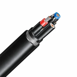
NTSKCGWÖU 0.6/1 (1.2) kV Mining Loader Cable
A related cable option for a different application or duty profile.
View product
(N)TMH3S 0.6/1 kV TPU Mining Reeling Cable
A related cable option for a different application or duty profile.
View productRequest a cable recommendation and quotation
Send the required services, cable length, mechanical duty, environment, termination and quantity. Our team will review the application before quoting.
- Include the product name or SKU plus the required cable length and quantity.
- Attach a specification, drawing or data sheet when available.