









Type 241SF Flexible Mining Cable 1.1/1.1–11/11 kV
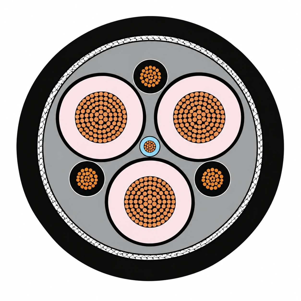
Type 241SF cable is a flexible underground mining power cable with three screened power cores, three earth conductors and one central pilot, covering 1.1/1.1 kV to 11/11 kV.
- Flexible tinned-copper conductors.
- EPR R-EP-90 insulation with semiconductive screens.
- Three interstitial earth conductors and a central extensible pilot.
- Open-weave textile reinforcement and an HD-85-PCP sheath.
- Power-conductor sizes from 70 to 300 mm², depending on voltage.
- AS/NZS 1802 design reference.
Type 241SF cable for flexible underground connections
Type 241SF cable supplies underground mining equipment through three screened power cores, three earth conductors and one central pilot. The family covers 1.1/1.1, 3.3/3.3, 6.6/6.6 and 11/11 kV, with tinned-copper conductors, EPR insulation and an HD-85-PCP outer sheath.
The SF construction uses a flexible conductor and lay-up arrangement for continuous-miner supplies, pump feeders and monorail-fed distribution equipment. The three earth conductors occupy the spaces between the power cores, while the pilot runs through the centre. This arrangement keeps the power, earthing and pilot functions distinct at the equipment connection.
- Voltage selection: match the complete voltage designation to the supply and equipment schedule.
- Conductor selection: choose the phase area using load, circuit length and voltage-drop requirements.
- Installation space: use the size-specific diameter and mass tables to plan cable supports and termination space.
- Replacement identification: retain the SF designation, earth-core areas and pilot arrangement when comparing an existing lead.
The Specifications section groups all four SF voltage grades on this page. For other constructions, browse mining and tunnelling cables or use the mining cable selection guide to compare duty, voltage and installation requirements.
Type 241SF cable construction
Three semiconductive-screened power cores are laid up with three interstitial earth conductors and one central extensible pilot. Textile reinforcement sits beneath the outer sheath.
| Element | Construction |
|---|---|
| Power conductors | Three flexible tinned-copper conductors |
| Conductor separator / screen | Polyester tape where necessary at 1.1/1.1 kV; semiconductive conductor screen at 3.3 kV and above |
| Insulation | EPR compound, R-EP-90 |
| Insulation screen | Semiconductive elastomer |
| Phase identification | Printed numbers on the black semiconductive insulation screen |
| Earth conductors | Three flexible tinned-copper earth conductors with semiconductive elastomer covering, located in the interstices |
| Pilot | One extensible pilot at the cable centre |
| Reinforcement | Open-weave textile reinforcement |
| Outer sheath | Heavy-duty HD-85-PCP elastomer |
Continuous miners, pump feeders and monorail supplies
The SF design serves underground mining connections where a flexible screened cable is required.

- Continuous miners: flexible power connections with separate earth and pilot conductors.
- Pump feeders: screened supplies between distribution equipment and mining pumps.
- Monorail systems: cable supplies to distribution circuit breakers and longwall equipment.
- Equipment and duct routes: size selection uses the installation method, conductor load and circuit length.
Match the cable to the route
Use the conductor schedule, cable diameter and mass to plan supports, loop space and equipment entries. Keep the earth and pilot terminations aligned with the machine circuit drawing.
For the standard Type 241 construction, see Type 241 mining cable. The SF version retains its own size and construction schedule.
Type 241SF cable specifications and ordering sizes
| Parameter | Value |
|---|---|
| Voltage variants | 1.1/1.1; 3.3/3.3; 6.6/6.6; 11/11 kV |
| Maximum continuous operating temperature | +90 °C |
| Minimum installation temperature | −25 °C |
| Power / earth / pilot arrangement | 3 power cores + 3 earth cores + 1 central pilot |
Type 241.1 SF — 1.1/1.1 kV
| Configuration | Conductor diameter (mm) | Insulation (mm) | Earth area, each (mm²) | Sheath (mm) | Cable diameter (mm) | Mass (kg/100 m) |
|---|---|---|---|---|---|---|
| Type 241.1 SF 70 mm² | 12.1 | 1.8 | 12.5 | 5.3 | 52.7 | 525 |
| Type 241.1 SF 95 mm² | 13.6 | 2.0 | 12.5 | 5.8 | 57.6 | 635 |
| Type 241.1 SF 120 mm² | 15.6 | 2.1 | 13.75 | 6.3 | 63.6 | 785 |
| Type 241.1 SF 150 mm² | 17.5 | 2.3 | 17 | 6.7 | 69.2 | 955 |
| Type 241.1 SF 185 mm² | 19.0 | 2.5 | 22 | 7.3 | 74.8 | 1115 |
| Type 241.1 SF 240 mm² | 21.9 | 2.8 | 27 | 8.0 | 83.7 | 1405 |
| Type 241.1 SF 300 mm² | 24.4 | 3.0 | 35.7 | 8.7 | 91.2 | 1715 |
| Configuration | AC resistance, 90 °C / 50 Hz (Ω/km) | Reactance, 50 Hz (Ω/km) | 3-phase voltage drop, 90 °C / 50 Hz (mV/A·m) | Capacitance to earth (µF/phase/km) |
|---|---|---|---|---|
| Type 241.1 SF 70 mm² | 0.346 | 0.0985 | 0.623 | 0.619 |
| Type 241.1 SF 95 mm² | 0.271 | 0.0968 | 0.498 | 0.622 |
| Type 241.1 SF 120 mm² | 0.210 | 0.0938 | 0.398 | 0.673 |
| Type 241.1 SF 150 mm² | 0.166 | 0.0922 | 0.329 | 0.685 |
| Type 241.1 SF 185 mm² | 0.137 | 0.0898 | 0.284 | 0.674 |
| Type 241.1 SF 240 mm² | 0.107 | 0.0881 | 0.240 | 0.689 |
| Type 241.1 SF 300 mm² | 0.0851 | 0.0862 | 0.210 | 0.736 |
Type 241.3 SF — 3.3/3.3 kV
| Configuration | Conductor diameter (mm) | Insulation (mm) | Earth area, each (mm²) | Sheath (mm) | Cable diameter (mm) | Mass (kg/100 m) |
|---|---|---|---|---|---|---|
| Type 241.3 SF 70 mm² | 12.1 | 3.0 | 12.5 | 6.4 | 60.9 | 635 |
| Type 241.3 SF 95 mm² | 13.6 | 3.0 | 16 | 6.8 | 64.8 | 750 |
| Type 241.3 SF 120 mm² | 15.6 | 3.0 | 20 | 7.2 | 70.0 | 900 |
| Type 241.3 SF 150 mm² | 17.5 | 3.0 | 27 | 7.6 | 74.8 | 1075 |
| Type 241.3 SF 185 mm² | 19.0 | 3.0 | 35.2 | 8.0 | 78.9 | 1225 |
| Type 241.3 SF 240 mm² | 21.9 | 3.0 | 39.5 | 8.6 | 86.2 | 1485 |
| Type 241.3 SF 300 mm² | 24.4 | 3.0 | 50 | 9.1 | 92.7 | 1775 |
| Configuration | AC resistance, 90 °C / 50 Hz (Ω/km) | Reactance, 50 Hz (Ω/km) | 3-phase voltage drop, 90 °C / 50 Hz (mV/A·m) | Capacitance to earth (µF/phase/km) |
|---|---|---|---|---|
| Type 241.3 SF 70 mm² | 0.346 | 0.107 | 0.627 | 0.422 |
| Type 241.3 SF 95 mm² | 0.271 | 0.103 | 0.502 | 0.461 |
| Type 241.3 SF 120 mm² | 0.210 | 0.0991 | 0.402 | 0.517 |
| Type 241.3 SF 150 mm² | 0.166 | 0.0961 | 0.332 | 0.568 |
| Type 241.3 SF 185 mm² | 0.137 | 0.0924 | 0.286 | 0.600 |
| Type 241.3 SF 240 mm² | 0.107 | 0.0891 | 0.241 | 0.675 |
| Type 241.3 SF 300 mm² | 0.0851 | 0.0867 | 0.210 | 0.744 |
Type 241.6 SF — 6.6/6.6 kV
| Configuration | Conductor diameter (mm) | Insulation (mm) | Earth area, each (mm²) | Sheath (mm) | Cable diameter (mm) | Mass (kg/100 m) |
|---|---|---|---|---|---|---|
| Type 241.6 SF 70 mm² | 12.1 | 5.0 | 12.5 | 7.4 | 72.0 | 820 |
| Type 241.6 SF 95 mm² | 13.6 | 5.0 | 16 | 7.9 | 76.1 | 945 |
| Type 241.6 SF 120 mm² | 15.6 | 5.0 | 20 | 8.3 | 81.3 | 1110 |
| Type 241.6 SF 150 mm² | 17.5 | 5.0 | 27 | 8.6 | 85.8 | 1290 |
| Type 241.6 SF 185 mm² | 19.0 | 5.0 | 35.2 | 9.0 | 89.9 | 1445 |
| Type 241.6 SF 240 mm² | 21.9 | 5.0 | 39.5 | 9.6 | 97.2 | 1725 |
| Type 241.6 SF 300 mm² | 24.4 | 5.0 | 50 | 10.2 | 104 | 2040 |
| Configuration | AC resistance, 90 °C / 50 Hz (Ω/km) | Reactance, 50 Hz (Ω/km) | 3-phase voltage drop, 90 °C / 50 Hz (mV/A·m) | Capacitance to earth (µF/phase/km) |
|---|---|---|---|---|
| Type 241.6 SF 70 mm² | 0.346 | 0.118 | 0.633 | 0.283 |
| Type 241.6 SF 95 mm² | 0.271 | 0.114 | 0.509 | 0.307 |
| Type 241.6 SF 120 mm² | 0.210 | 0.109 | 0.410 | 0.341 |
| Type 241.6 SF 150 mm² | 0.166 | 0.105 | 0.340 | 0.371 |
| Type 241.6 SF 185 mm² | 0.137 | 0.101 | 0.295 | 0.390 |
| Type 241.6 SF 240 mm² | 0.106 | 0.0971 | 0.249 | 0.436 |
| Type 241.6 SF 300 mm² | 0.0847 | 0.0941 | 0.219 | 0.478 |
Type 241.11 SF — 11/11 kV
| Configuration | Conductor diameter (mm) | Insulation (mm) | Earth area, each (mm²) | Sheath (mm) | Cable diameter (mm) | Mass (kg/100 m) |
|---|---|---|---|---|---|---|
| Type 241.11 SF 70 mm² | 12.1 | 7.6 | 12.5 | 8.9 | 86.4 | 1090 |
| Type 241.11 SF 95 mm² | 13.6 | 7.6 | 16 | 9.3 | 90.3 | 1225 |
| Type 241.11 SF 120 mm² | 15.6 | 7.6 | 20 | 9.7 | 95.5 | 1405 |
| Type 241.11 SF 150 mm² | 17.5 | 7.6 | 27 | 10.0 | 100.0 | 1600 |
| Type 241.11 SF 185 mm² | 19.0 | 7.6 | 35.2 | 10.4 | 104 | 1765 |
| Type 241.11 SF 240 mm² | 21.9 | 7.6 | 39.5 | 11.0 | 111 | 2080 |
| Configuration | AC resistance, 90 °C / 50 Hz (Ω/km) | Reactance, 50 Hz (Ω/km) | 3-phase voltage drop, 90 °C / 50 Hz (mV/A·m) | Capacitance to earth (µF/phase/km) |
|---|---|---|---|---|
| Type 241.11 SF 70 mm² | 0.346 | 0.129 | 0.640 | 0.212 |
| Type 241.11 SF 95 mm² | 0.271 | 0.125 | 0.517 | 0.229 |
| Type 241.11 SF 120 mm² | 0.210 | 0.119 | 0.418 | 0.252 |
| Type 241.11 SF 150 mm² | 0.165 | 0.115 | 0.348 | 0.273 |
| Type 241.11 SF 185 mm² | 0.136 | 0.110 | 0.303 | 0.286 |
| Type 241.11 SF 240 mm² | 0.106 | 0.106 | 0.260 | 0.317 |
Dimensions and mass are nominal. AC resistance is stated at 90 °C and 50 Hz; reactance at 50 Hz; three-phase voltage drop at 90 °C and 50 Hz. Capacitance is per phase to earth per kilometre.
Type 241SF standards
The design reference is AS/NZS 1802 — underground coal-mining reeling and trailing cables. It covers reeling and trailing cables for underground coal-mining applications.
- Power-core insulation: EPR R-EP-90.
- Outer sheath: heavy-duty HD-85-PCP elastomer.
- Core arrangement: three power cores, three earth conductors and one central pilot.
Related cable options
Compare these cable options by service combination, movement, load, voltage and transmission requirement.
Type 241.1 Mining Cable 1.1 kV | Type 241 Family
A related cable option for a different application or duty profile.
View product
Type 240 Underground Coal Mine Cable 1.1kV to 11kV
A related cable option for a different application or duty profile.
View product
Type 245 Flexible Rubber Mining Cable 1.1–6.6 kV
A related cable option for a different application or duty profile.
View productRequest a cable recommendation and quotation
Send the required services, cable length, mechanical duty, environment, termination and quantity. Our team will review the application before quoting.
- Include the product name or SKU plus the required cable length and quantity.
- Attach a specification, drawing or data sheet when available.